Creating a Wardrobe detailed drawing, Floor Plan, Kitchen Layout and Column Detail using AutoCad
QUE-1 :
Draw the elevation and details of a wardrobe as shown in the Figure below. After sketching, you need to provide the dimensions and text with the use of layers. Use proper text styles and dimension methods to document it. Also, assume dimensions, wherever needed.
Note: All dimensions are in mm.
AIM: TO DRAW ELEVATION AND DETAILS OF A WARDROAB AS GIVEN IN FIGURE.
COMMNAD USED IN THIS FIGURE:
- line
- offset
- single line text
- layer
- mirror
- trim
- divid
- copy
- move
- dimension tool
PROSEDURE FOR DRAWING:
- first open autocad set the limits and units.
- all units are in mm.
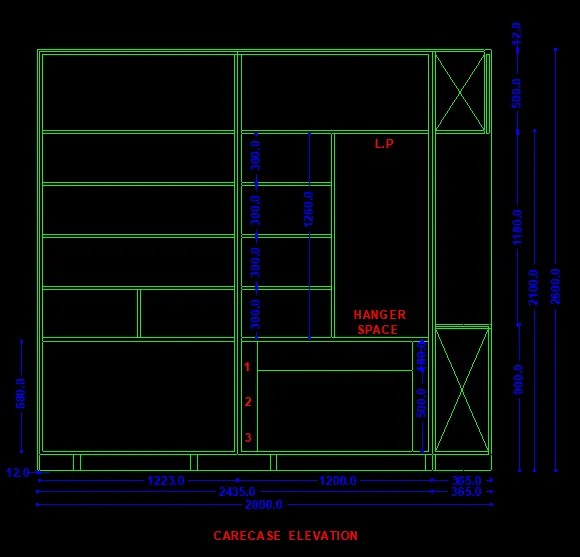
- first take LINE command and draw horizontal line of 2800 after that point draw vertically line of 2600.
- continue with the last point draw backward line of 2800 and complete the box.
- from the upper side give the offset of 12 and that last point give another offset of 480.
- now using divid command divid uper part in 4 part.
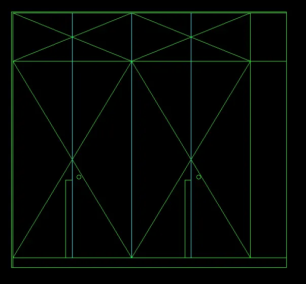
- now measure the dimension and put them to different layer.
- now using text command write down given text.
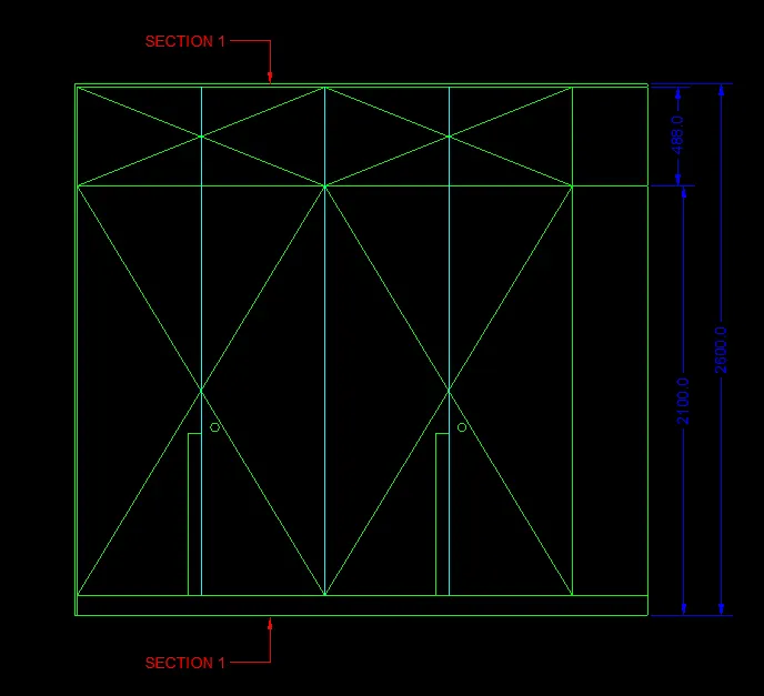
- now we have to draw onther cupbord with same method.
- in horizontal direction draw line of 2800 and vertically 2600.
- again draw line of 2800 in back direction and complete the box.
- next using offset commad give different offset they given in figure.
- first offset of 12 and from that line onther offset of 10.
- from the bottom give the offset of 100.
- now measuring all dimension from the given attechment and draw all inside line.
- give dimension of inside drawers are 300 mm.
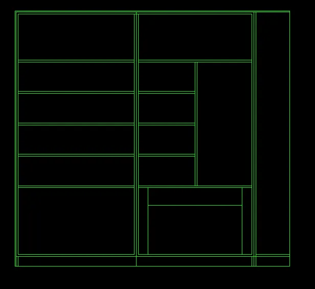
- now using text command write all text in drawing.
- using trim command remove extra part in drawing.
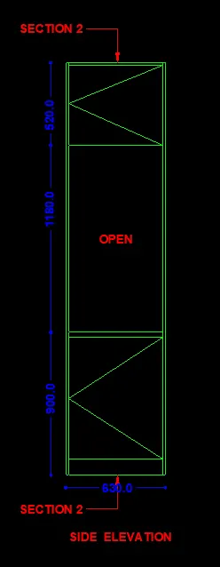
- now we draw side elivation of 630x2600.
- give the offset same as above 12 mm .
- now using text and dimension tool give dimension to them.
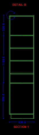
- same as last figure we have to draw onther cupboard of same dimension of 630 x 2600 .
- from the bottom line give offset of 500.
- from that point give onther offset of 1180 and using divid command divid them to 4 parts.
- now using text and dimension tool give text and dimension as given in attechment.
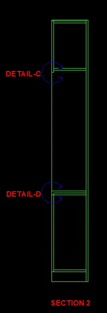
- now the same method and dimension draw next cupboard and give the offset of 12 and remove extra parts by trim.
- now for plan drawing draw line of 2800 in x direction and 630 in y direction.
- now give offset of 12 from the both side of plan.
- remove unnecessary part in drawing using trim command.
- using dimension tool give all dimension in figure.
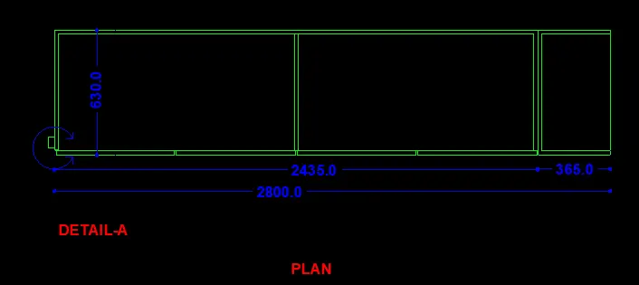
RESULT : ALL DRAWINGS ARE SUCCESFULLY DRAWEN IN AUTOCAD.
QUE-2 :
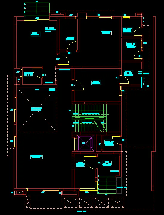
Draw the floor plan as shown in the Figure. Use the proper drafting tools to sketch the plan. Do not hatch or draw the furniture. You need to draw the floor plan with the following:
Note: You can also import the Floor_Plan.pdf into your current drawing and start working on the project. You need to scale the imported pdf file using reference option. All dimensions are in mm.
- Walls (Exterior and Interior)
Wall Thickness: Exterior Wall- 230mm, Interior Wall: 150 mm (Wherever Required)
- Doors and Windows: Assume the size of the doors and window.
2.1 Stairs: Tread-300mm, Riser-150mm
- Insert Text wherever required
- Insert the dimensions using proper dimension techniques
AIM: TO DRAW A FLOOR PLAN GIVEN IN FIGURE.
COMMNAD USED IN THIS FIGURE:
- line
- offset
- single line text
- layer
- trim
- copy
- move
- dimension tool
PROSEDURE FOR DRAWING:
- first open autocadd and set the units .
- after that we have to make layer properties for different sets of drawing.
- now using line command we draw all external wall and inner wall. thickness of all wall are as below
- exterior wall = 230mm and interior wall = 150mm .
- for the measuring dimension we can also import PDF file to autocad from the toolbar and we can measure missing dimension from them.
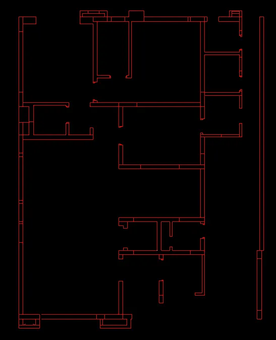
- now we have to draw all doors and window as they given.
- for the dimension of window and door we can assume that or we can also measure from the imported pdf file.
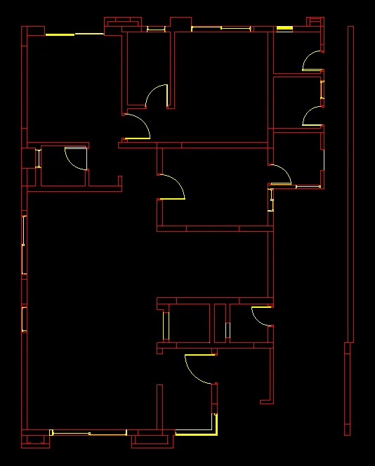
- now we have to draw lift and stairs.
- dimension of stairs are given for tread = 300mm and for riser=150mm.
- also draw center lines as they given in drawing.
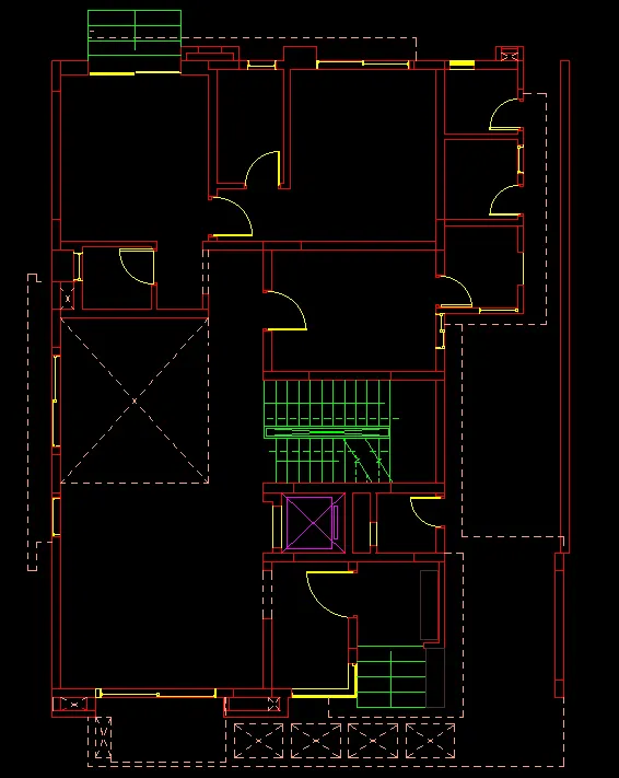
- in final step we have to dimension them and writedown all text using singel line and double line command.
- remove unnecessary part in drawing using trim command.
RESULT : ALL DRAWINGS ARE SUCCESFULLY DRAWEN IN AUTOCAD.
QUE-3 :
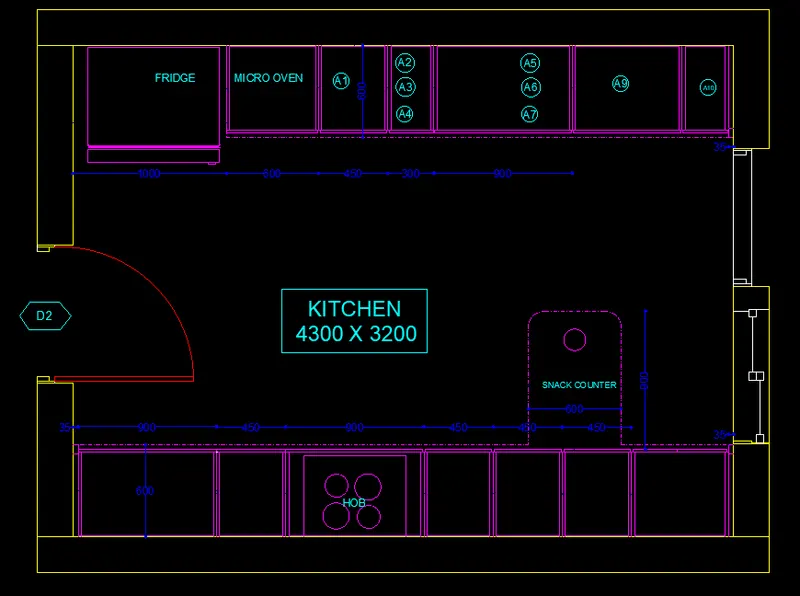
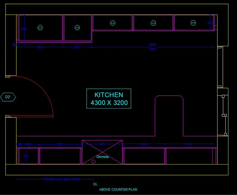
Create the Kitchen Layout as shown in the Figure below. Also, use proper dimension techniques to dimension the kitchen layout. Also, insert text wherever required. All dimensions are in mm.
AIM: CREAT A KITCHEN LAYOUT AS THEY GIVEN IN FUGURE
COMMNAD USED IN THIS FIGURE:
- line
- offset
- single line text
- layer
- trim
- copy
- move
- dimension tool
PROSEDURE FOR DRAWING:
- first open autocad and set the units in mm.
- now using line command draw a recatngular box of 4300x3200.
- now give offset of 230.
- now we have to draw fridge oven and onther parts in kitchen using diffrent command like offset,copu,move,trim.
- all dimension are given in attechment and if we have to measure any missing dimenssion then we can import pdf file and measure those all dimension .
- using trim command remove unnecessary part in drawing.
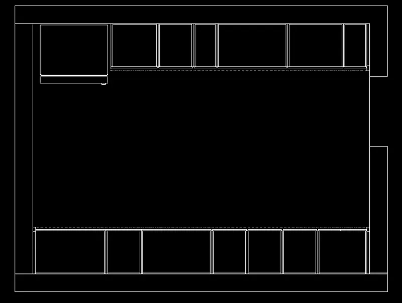
- now with different layer properties give to drawing.
- using text command and dimension tool measure all dimension in drawing.
- for onther kitchen room same as above method draw rectangular box using line command of 4300x3200.
- from the top line give offset of 600mm and inner offset of 20mm.
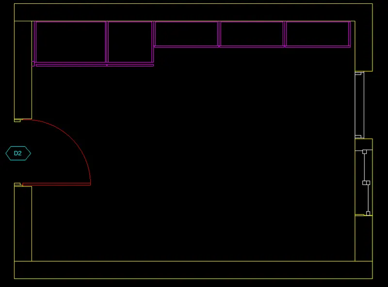
- from the bottom line give the offset of 350 mm.
- continue with same method draw all part in kitchen using offset command.
- now using dimension tool give all dimension to drawing and remove unnecessary parts in drawing.
RESULT : ALL DRAWINGS ARE SUCCESFULLY DRAWEN IN AUTOCAD.
QUE-4:
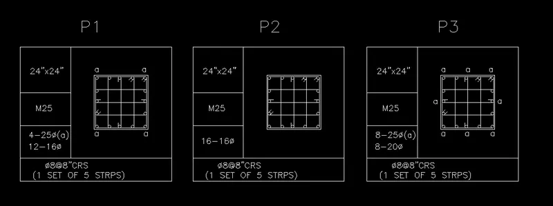
Sketch the column details as shown in Figure. Insert dimensions and text in the figure. Refer to the bar sizes from the schedule.
8mm ---- 0.31 Inches
25mm--- 1 inches
16mm—0.62 inches
AIM: CREAT A BAR BENDING SCHEDULE AS GIVEN IN FIGURE.
COMMNAD USED IN THIS FIGURE:
- line
- circle
- offset
- single line text
- trim
- mirror
- copy
- move
- dimension tool
PROSEDURE FOR DRAWING:
- first open autocad and set the limits .
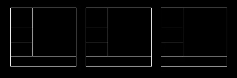
- now we have to draw three box for detailing of bar.
- assume dimension and draw three box.
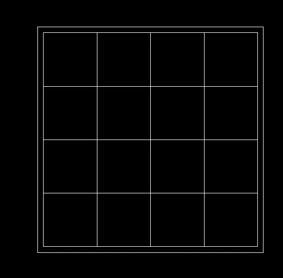
- now draw one rectangular using line command of 24"x24".
- give offset of 5.
- now in inner rectangular give divid command and part them in 4 section.
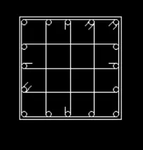
- now using circle command draw all bars as they given in figure.
- for strps give 45degree rotate.
- trim unnecessary part in drawing,
- now copy this figure 3 times and put those all figure in box.
- write all details using single line command.
RESULT : ALL DRAWINGS ARE SUCCESFULLY DRAWEN IN AUTOCAD.
QUE-5:
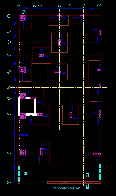
Draw the Raft Layout as shown in the Figure. Assume the column size as per your knowledge. You can take the sizes as: 24”x24”, 9” x 24”, 9” x 18”, and 9’ x 24”. You can import the raft_foundation.pdf to ensure the missing dimensions.
AIM: CREAT A RAFT LAYOUT AS THEY GIVEN IN FIGURE.
COMMNAD USED IN THIS FIGURE:
- line
- linetype
- offset
- single line text
- trim
- copy
- dimension tool
PROSEDURE FOR DRAWING:
- first open autocad set units to arctitectal set pricision to 0' 0 1/2" .
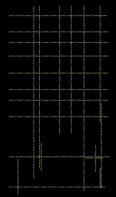
- now select the line type and select doted line type.
- now using line command draw all verticall and horizontal line as they given in figure.
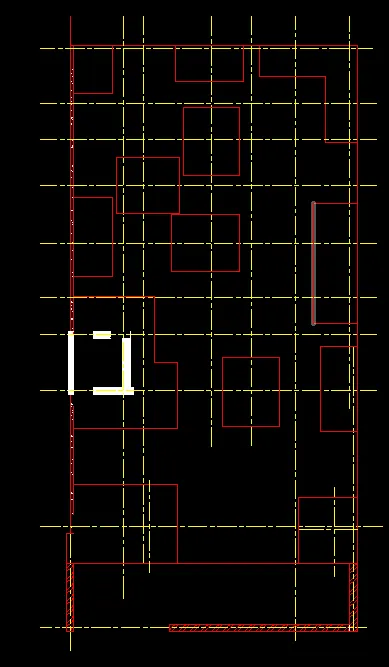
- now using line command we draw external and inner line with different layer.
- for measurement of missing dimension we can import pdf file to autocad and measure those dimension .
- now we have to draw all column deatail .
- there are three different types of column . we can take the size as : 24”x24”, 9” x 24”, 9” x 18”, and 9’ x 24”.
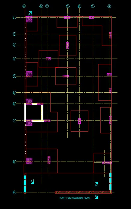
- now using dimension tool measure all dimension in figure.
- remove unnecessary part in drawing.
RESULT : ALL DRAWINGS ARE SUCCESFULLY DRAWEN IN AUTOCAD.