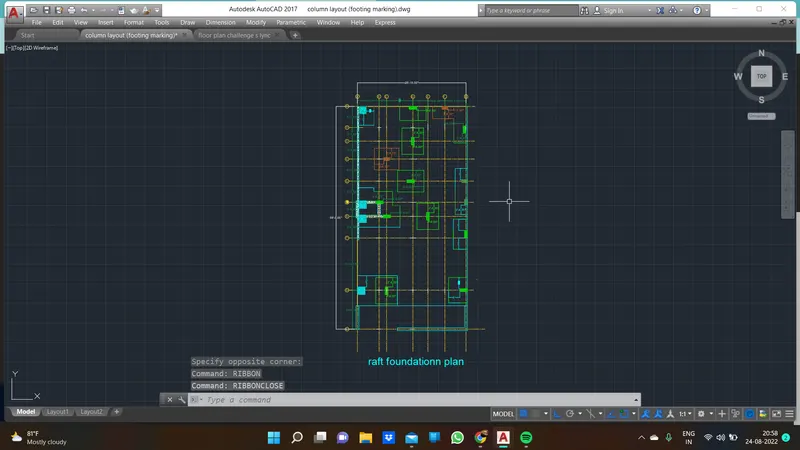
Creating a Wardrobe detailed drawing, Floor Plan, Kitchen Layout and Column Detail using AutoCad
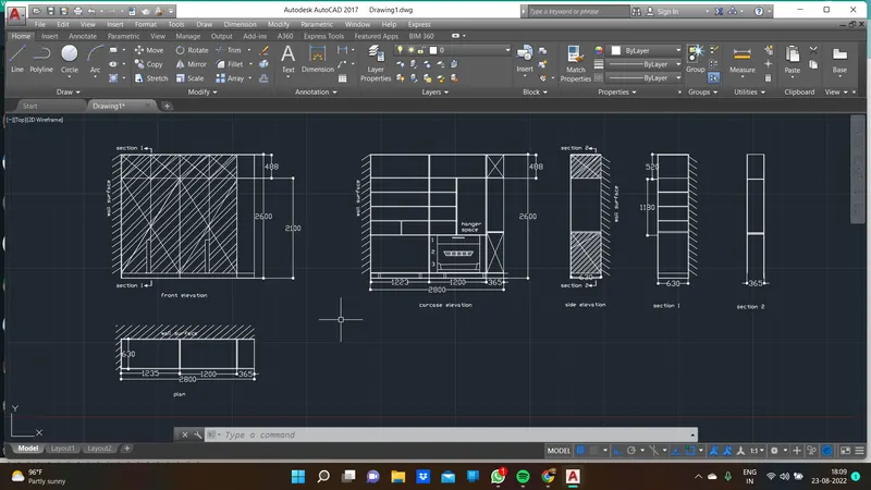
1. Draw the elevation and details of a wardrobe as shown in the Figure below. After sketching, you need to provide the dimensions and text with the use of layers. Use proper text styles and dimension methods to document it. Also, assume dimensions, wherever needed.
Note: All dimensions are in mm.
aim:to draw the wardrobe used autocadd tools
tools used:
line
offset
copy
hatch
polyline
multitext
dim
procedure:
make a line for create the wardrobe outer
copy the object for section
offset is for make a same line vice versa
dim is used to show the dimension
mtext has been used to show the text
2.
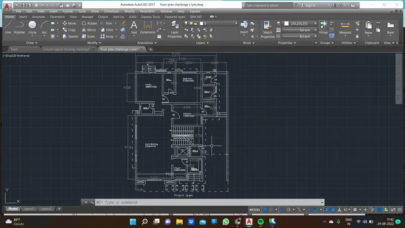
Q2. Draw the floor plan as shown in the Figure. Use the proper drafting tools to sketch the plan. Do not hatch or draw the furniture. You need to draw the floor plan with the following:
Note: You can also import the Floor_Plan.pdf into your current drawing and start working on the project. You need to scale the imported pdf file using reference option. All dimensions are in mm.
- Walls (Exterior and Interior)
Wall Thickness: Exterior Wall- 230mm, Interior Wall: 150 mm (Wherever Required)
- Doors and Windows: Assume the size of the doors and window.
2.1 Stairs: Tread-300mm, Riser-150mm
- Insert Text wherever required
- Insert the dimensions using proper dimension techniques
aim:
to draw the floor plan , use the proper sketching, drafting....
tools used:
line
offset
copy
mirror
arc
mtext
tcount
dim
etc...
procedure:
line is used to draw the walls rooms
offset is created for seperate the room
start end direction arc is used for to create the doors
mtext is used to show the named area
tcount is used in the stair for seq of numbers
dotted line is used to show the sunshade
result:
3. Create the Kitchen Layout as shown in the Figure below. Also, use proper dimension techniques to dimension the kitchen layout. Also, insert text wherever required. All dimensions are in mm.
aim :
to create kitchen layout using autocadd tool
tools used:
line
offset
copy
mirror
arc
mtext
tcount
dim
etc...
procedure:
line tool has been used
circle has been used
arc is used to create the door
hatch has been used for the wall
mtext is used
dim is used to know the each area distance
result: 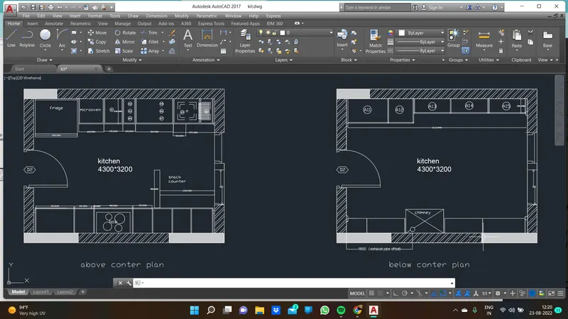
Q4. Sketch the column details as shown in Figure. Insert dimensions and text in the figure. Refer to the bar sizes from the schedule.
8mm ---- 0.31 Inches
25mm--- 1 inches
16mm—0.62 inches
aim:Sketch the column details as shown in Figure. Insert dimensions and text in the figure. Refer to the bar sizes from the schedule.
tools used:
line
m text
circle in dia
procedure:
line is used for the draw the column
circle dia is to draw the dia of rebar
text is used to show the details for the column
result:
tools used: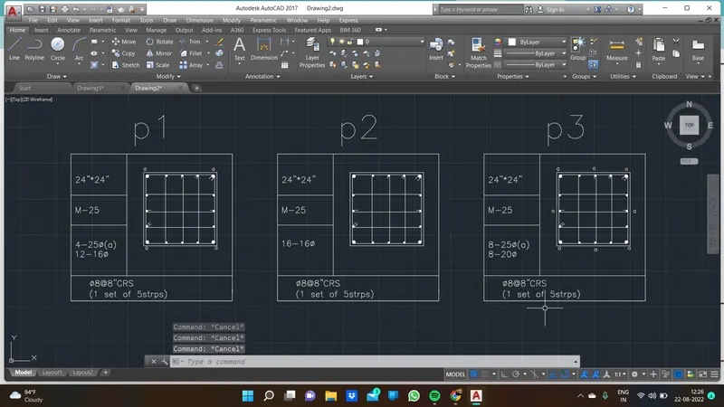
5:Draw the Raft Layout as shown in the Figure. Assume the column size as per your knowledge. You can take the sizes as: 24”x24”, 9” x 24”, 9” x 18”, and 9’ x 24”. You can import the raft_foundation.pdf to ensure the missing dimensions.
aim: draw the footing layout for the floor
tools used
line
circle
mtext
hatch
dim
offset
copy
colour
procedure:
draw the line for show the grid lines
grid lines are drew in x and y direction
dotted line has been used
excavation boundary is drew along with that colum has been draw these are fix at the centre to centre distance of a 1 b2 c3 etc
dim used to measure the length and width
text has been used to give the details
result: