Creating a Wardrobe detailed drawing, Floor Plan, Kitchen Layout and Column Detail using AutoCad
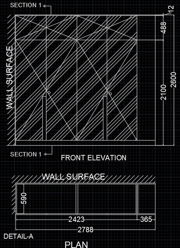
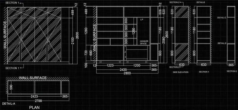
- Draw the elevation and details of a wardrobe as shown in the Figure below. After sketching, you need to provide the dimensions and text with the use of layers. Use proper text styles and dimension methods to document it. Also, assume dimensions, wherever needed.
Note: All dimensions are in mm.
AIM:
To draw the elevation and details of wardrobe by using the drafting tools in AutoCAD.
INTRODUCTION:
A wardrobe is a standing closet used for soring clothes. The earliest wardrobe was a chest, and it as not until some degree of luxury was attained in regular places and the castles of powerful nobles that separate accommodation was provided for the apparel of the great.
PROCEDURE:
WREBOARD SKETCHING
Step-1:
Sketching the plan and front elevation of wardrobe:
- First, we sketch the plan of a wardrobe and then we sketch the front elevation.
- Select the command LINE and draw the outer and inner lines of the plan and front elevation.
- Use the command OFFSET to sketch the parallel lines for inner and outer lines.
- Use command TRIM to eliminate the unwanted lines.
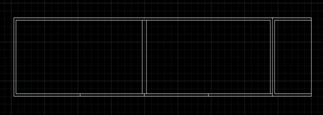
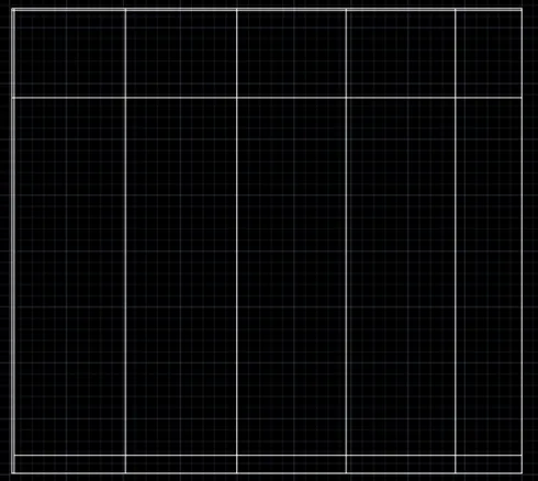
- After completing the sketch, use the command HATCH to highlight the sketch.
- After that use the command DTEXT and write the required text.
- Use the command DTEXT and select the option rotate for write the text in 900
- Use command DIMLIN to specify the dimensions by using the options Continue and Baseline for required dimensional specifications.
- Finally use the command LINE and command CIRCLE for completing the additional works (design on doors, handle).
Step-2:
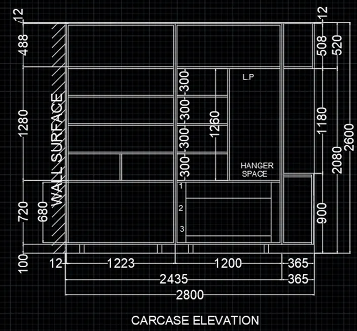
Sketching of wardrobe carcase elevation:
- After completing the sketch of plan and front elevation of wardrobe, then we have to sketch the carcase elevation.
- Select the command LINE and draw the outer and inner lines of the carcase.
- Use the command OFFSET to sketch the parallel lines for inner and outer lines.
- Use command TRIM to eliminate the unwanted lines.
- After that use the command DTEXT and write the required text.
- Use the command DTEXT and select the option rotate for write the text in 900
- Use command DIMLIN to specify the dimensions by using the options Continue and Baseline for required dimensional specifications.
- Finally use the command LINE for completing the additional works.
Step-3:
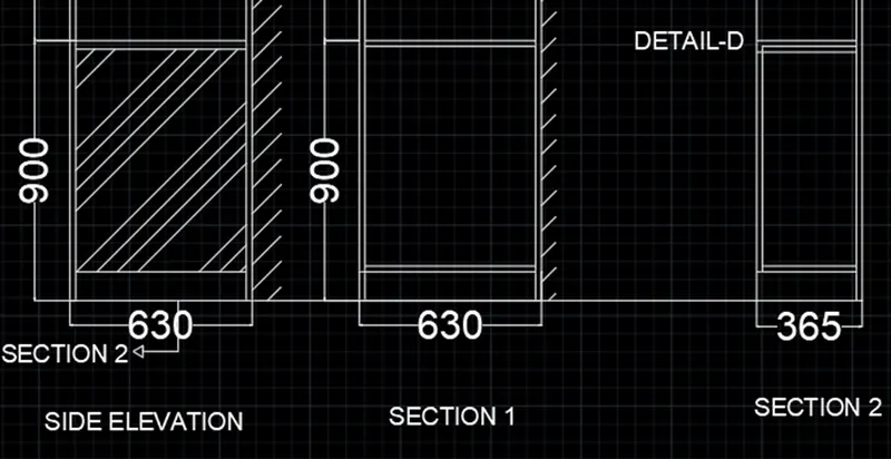
Sketching of wardrobe side elevation and section 1&2:
- After completing the sketch of carcase elevation of wardrobe, then we have to sketch the side elevation.
- Select the command LINE and draw the outer and inner lines of the carcase.
- Use the command OFFSET to sketch the parallel lines for inner and outer lines.
- Use command TRIM to eliminate the unwanted lines.
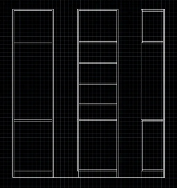
- After that use the command DTEXT and write the required text.
- Use command DIMLIN to specify the dimensions by using the options Continue and Baseline for required dimensional specifications.
RESULT:
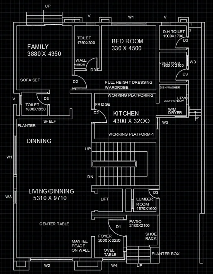
Q2. Draw the floor plan as shown in the Figure. Use the proper drafting tools to sketch the plan. Do not hatch or draw the furniture. You need to draw the floor plan with the following:
Note: You can also import the Floor_Plan.pdf into your current drawing and start working on the project. You need to scale the imported pdf file using reference option. All dimensions are in mm.
- Walls (Exterior and Interior)
Wall Thickness: Exterior Wall- 230mm, Interior Wall: 150 mm (Wherever Required)
- Doors and Windows: Assume the size of the doors and window.
2.1 Stairs: Tread-300mm, Riser-150mm
- Insert Text wherever required
- Insert the dimensions using proper dimension techniques
AIM:
To sketch the floor plan by using the drafting tool in AutoCAD.
INTRODUCTION:
Floor plan is a technical drawing to scale, showing a view from above of the relationships between the rooms, spaces, traffic patterns and ther physical features at one level of a structure.
PROCEDURE:
STEP-1:
- First, we take the command XLINE, draw the horizontal and vertical lines.
- Then use the command OFFSET, draw the thickness of external wall and draw the interior walls of the plan as per given dimensions.
- Use the command TRIM and erase the all the external excessive lines.
- After completion of external walls, now we have to sketch the interior walls properly by using the command LINE.
- After completion of interior walls, now we have to sketch the space for doors, windows, ventilators as per given dimensions by using the command LINE.
- Use the command TRIM to create the space for doors.
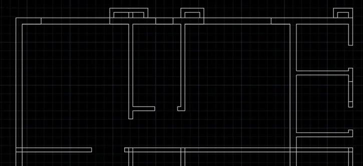
- After completing the sketch of the first part, the procedure is followed for second part of plan.
- To draw the interior walls and to sketch the space for doors, windows, ventilators as per given dimensions by using the command LINE.
- To sketch staircase, we use command OFFSET, command LINE to complete the works.
- After complete the sketch, use command TRIM to erase the unwanted lines and crate the space for doors.
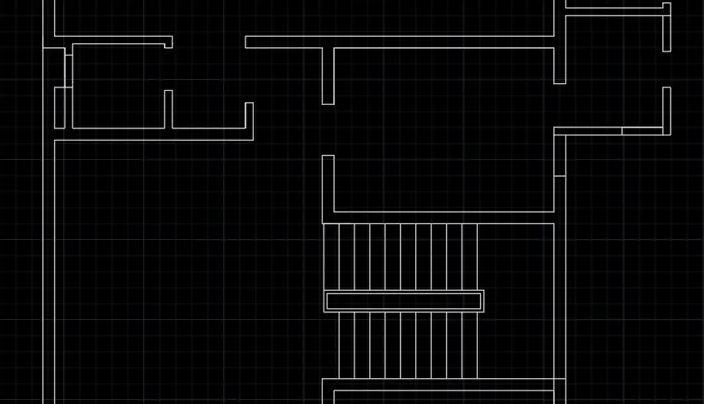
- After completing the sketch of the second part, the procedure is followed for third part of plan.
- To draw the interior walls and to sketch the space for doors, windows, ventilators as per given dimensions by using the command LINE.
- To sketch staircase, we use command OFFSET, command LINE to complete the works.
- After complete the sketch, use command TRIM to erase the unwanted lines and crate the space for doors.
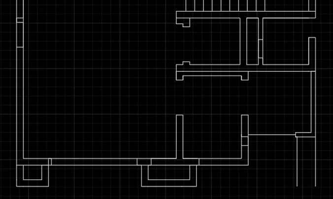
STEP-2:
- After completing the sketch of the floor plan, we should have to give the text, dimensions to the floor plan.
- Firstly, give the dimensions for the plan and representing them by using command
- Then place the text between the lines as table by using the command
- After that use the command MOVE to place the sketch between the table.
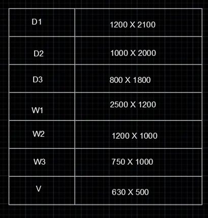
- Select the command LINE, command OFFSET and command CIRCLE to complete the sketching of doors, windows, ventilators, steps etc.
- After completed the sketch of all the parts of plan, then we have to label and give dimensions to them.
- Select the command DTEXT and labelling the plan as per required places as rooms, toilets, doors, windows, ventilators etc.
- Use command DIMLIN to specify the dimensions by using the options Continue and Baseline for required dimensional specifications.
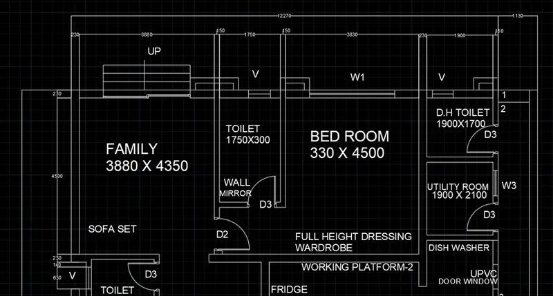
- Continue the same process for completing the floor plan.
RESULT:
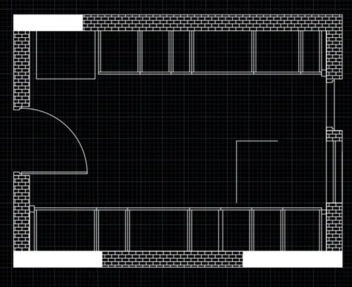
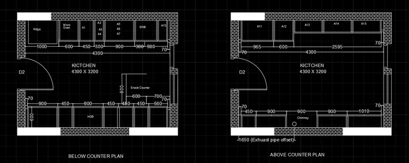
Q3. Create the Kitchen Layout as shown in the Figure below. Also, use proper dimension techniques to dimension the kitchen layout. Also, insert text wherever required. All dimensions are in mm.
AIM:
To create the layout of kitchen by using the drafting tools in AutoCAD.
PROCEDURE:
Step-1:
- First, we sketch the layout of kitchen.
- Select the command LINE and draw the outer line of kitchen.
- Use the command OFFSET to sketch the parallel lines for outer lines.
- Use command TRIM to eliminate the unwanted lines.
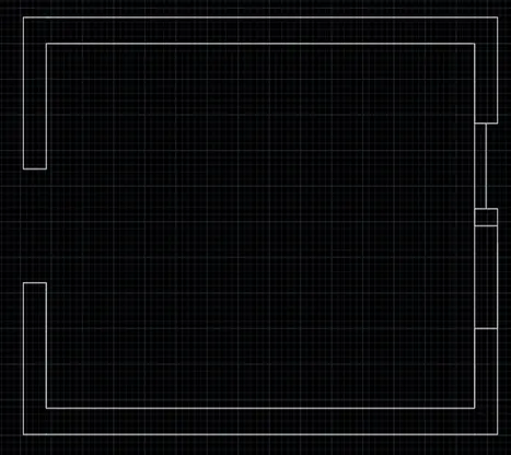
STEP-2:
- After completing the outer layer, we should draw the furniture area.
- Select the command LINE and draw the interior space for required dimensions.
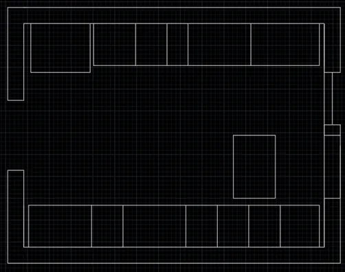
- Use the command OFFSET to sketch the parallel lines.
- Select the command CIRCLE to sketch the door.
- Use command TRIM to eliminate the unwanted lines.
- Then use the command HATCH and select the pattern BRICK, SOLID for highlight the sketch.
STEP-3:
- After completing the drawing, we should mention the dimensions and labelling fo sketch.
- Select the command DTEXT and write the required text.
- Use command DIMLIN to specify the dimensions by using the options Continue and Baseline for required dimensional specifications.
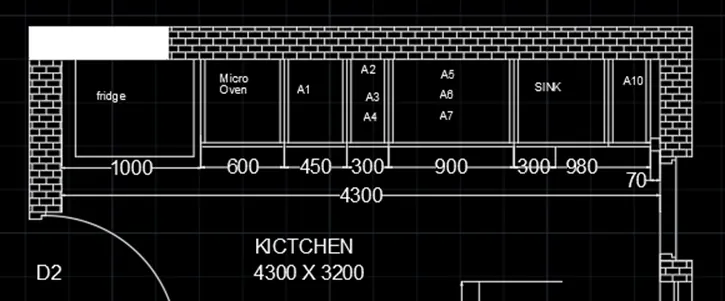
- Follow the same process for above counter plan.
RESULT:
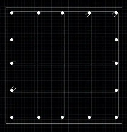
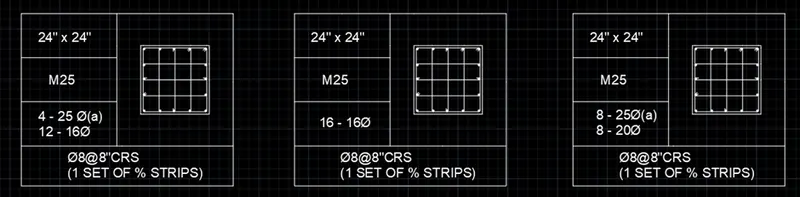
Q4. Sketch the column details as shown in Figure. Insert dimensions and text in the figure. Refer to the bar sizes from the schedule.
8mm ---- 0.31 Inches
25mm--- 1 inches
16mm—0.62 inches
AIM:
To Create a column schedule by using the drafting tools in the AutoCAD.
INTRODUCTION:
Column Schedule:
Structural columns are identified in a column schedule by inserting grid lines and by their top and bottom constraints and offsets. They are placed into the column schedules according to these identifications.
PROCEDURE:
Step by step procedure for sketching the column details for 8mm.
STEP-1:
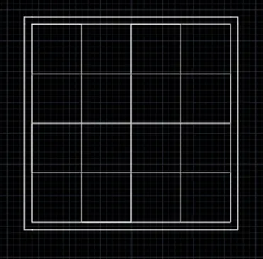
- Firstly, draw the outer layer of the column and reinforced bars.
- Select the command LINE to draw the lines vertically and horizontally at required dimensions.
- Use the command OFFSET to draw the parallel lines.
- Use the command TRIM to eliminate the unwanted lines.
STEP-2:
- After completing the bars and outer layer, we should draw the vertical bars.
- Representing the vertical bars by using the command
- Use the command FILLET with required radius for curve the lines.
- Use the command HATCH and select the pattern SOLID for highlight the bars.
STEP-3:
- Select the command DTEXT and write the required text.
- Symbol for diameter, we use (%%c).
- After the write the text, use the command LINE and command OFFSET to sketch the table around the text.
- Use command TRIM to eliminate the unwanted lines.
- Use the command MOVE to place the text at the centre of specified place.
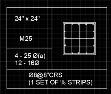
- The same procedure is followed for 16mm and 25mm.
RESULT:
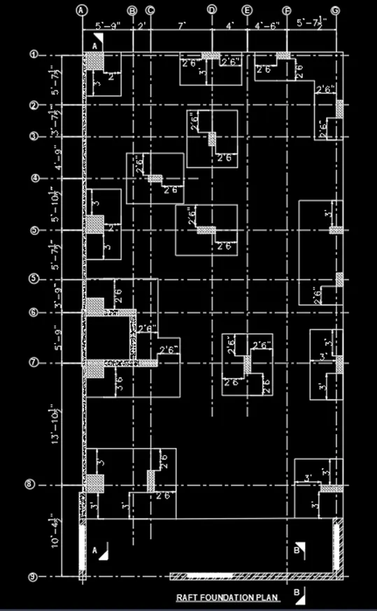
Draw the Raft Layout as shown in the Figure. Assume the column size as per your knowledge. You can take the sizes as: 24”x24”, 9” x 24”, 9” x 18”, and 9’ x 24”. You can import the raft_foundation.pdf to ensure the missing dimensions.
AIM:
To draw the raft layout for the given column sizes by using the drafting tools in AutoCAD.
INTRODUCTION:
Raft foundation is generally used to support structure like residential or commercial buildings where soil condition is poor, storage tanks, soils, foundation for heavy industrial equipment etc.
PROCEDURE:
Step by step procedure for sketching raft layout.
STEP-1:
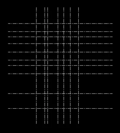
- First step is to select the command XLINE and draw the one horizontal line and one vertical line.
- Use the command OFFSET draw the parallel lines horizontally and vertically as per the given dimensions.
- Select the layer properties to create a Layer as grid lines and give the line type as

- Use the command TRIM to eliminate the unwanted lines.
STEP-2:
- After completing the drawing of grid lines as per the dimensions. Now we have to sketch the columns and raft foundation.
- Select command LINE and draw the outer layer of the plan.
- Use the command DTEXT to represent the grid lines as A, B, C… and 1, 2, 3….
- Use the command LINE and draw the columns and raft foundation at specified places as per the given dimensions.
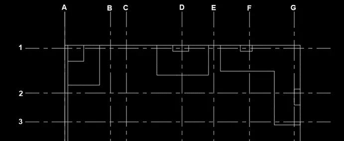
- Continue the same procedure for completing the raft layout.
STEP-3:
- After completing the raft layout plan, now we have to complete the remaining work.
- select the command CIRCLE to place the text of representing grid lines between the circles.
- Use the command DIMLIN and specify the dimensions by using the option continue.
- Then use the command HATCH and select the pattern ANSI37 for columns representation and pattern AR-CONC for specified places.
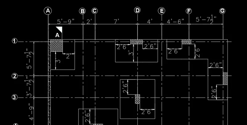
- The same procedure is continued for completing the aft layout.
- Then use the command DTEXT for labelling the plan.
- Then use the command HATCH and select the pattern ASNI32 for highlight the sketch.
- Use the command TRIM and eliminate the unwanted lines.
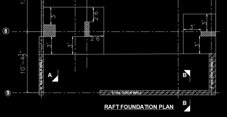
RESULT: