Creating a Wardrobe detailed drawing, Floor Plan, Kitchen Layout and Column Detail using AutoCad
(1)AIM :Draw the Elevation and details of wardrobe.
Introduction : we create plan, elevation and section details of wardrobe in AUTOCAD . we provide screenshots of every steps.we are using decimal,architectural and engineering units as required in plan. we use proper layers to show the dimension and text of elements.
Procedure :
- first choose units and limits before creating any figure.
-
for units, Type command - "UN"
for limits, Type command - "LIM"
- First create plan and we use line,fillet,offset command. set the dimension size using 'D' command
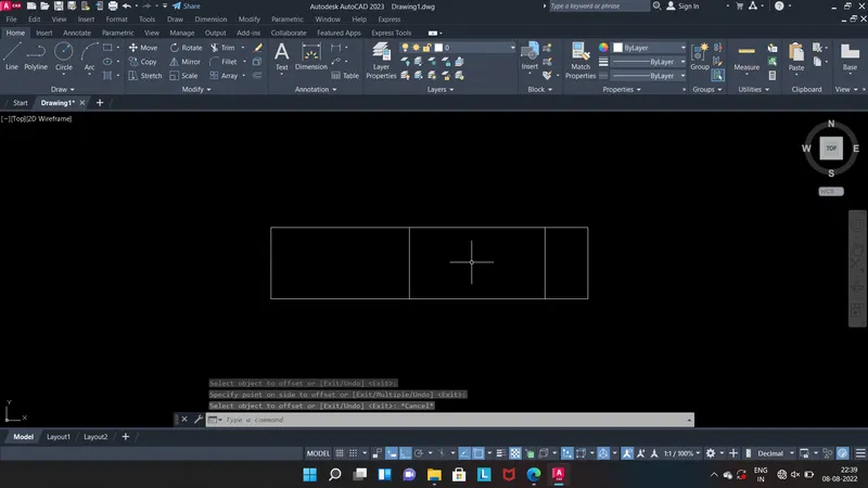
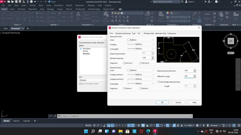
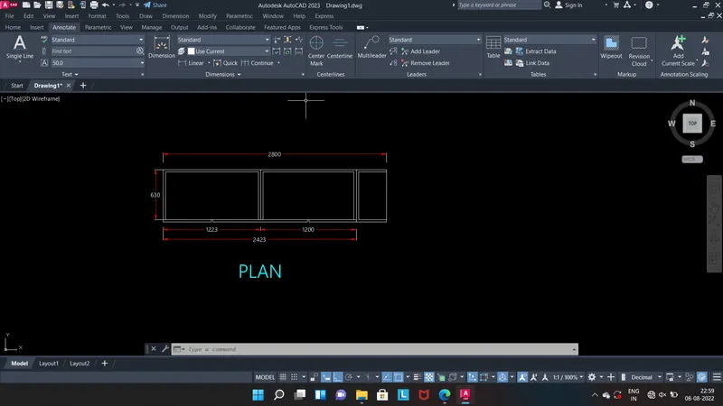
- now using xline on plan to create elevation of wardrobe and incline x line is used to create pattarn on it. Here layer is used to show the pattern,text and dimension different.
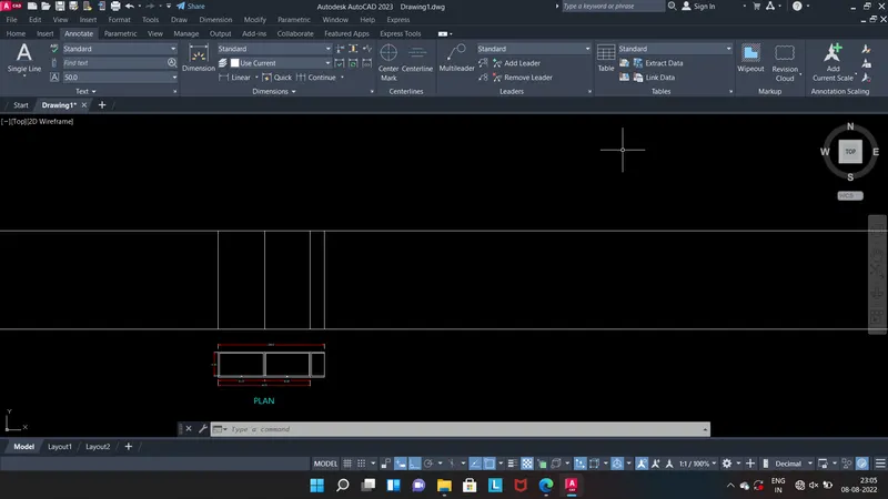
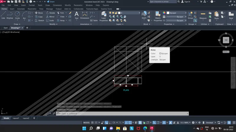
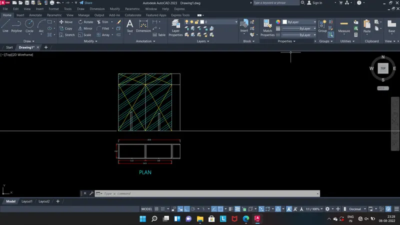
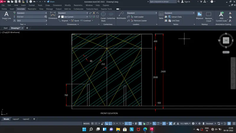
- After creating front elevation now, creating carcase elevation. here i used x line to project the height of front elevation
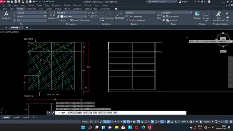
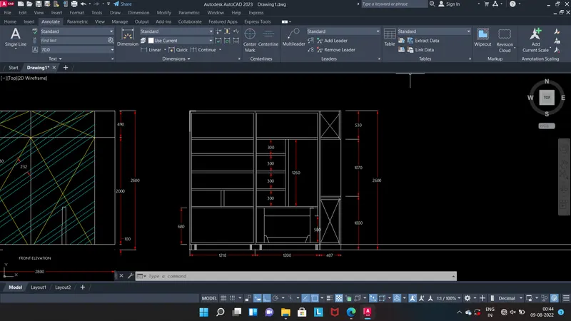
- after creating all components above,now creating section and side elevation of wardrobe.
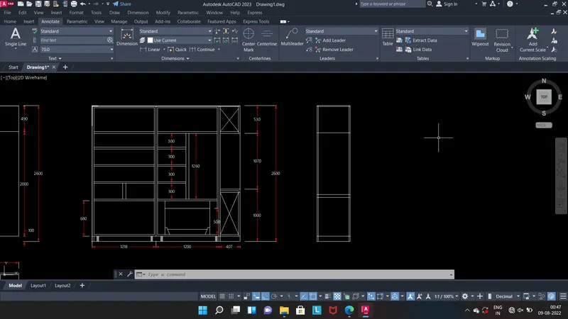
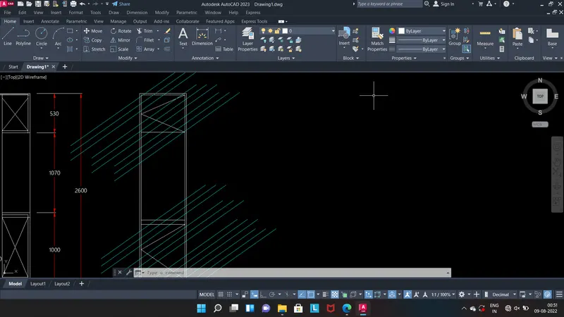
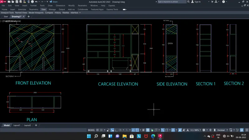
FINAL RESULT: Layers is used to show the dimension and text differents and some dimension is assumed and here is final results.
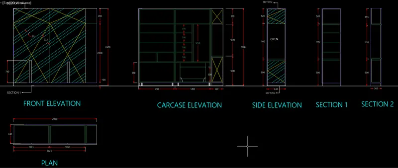
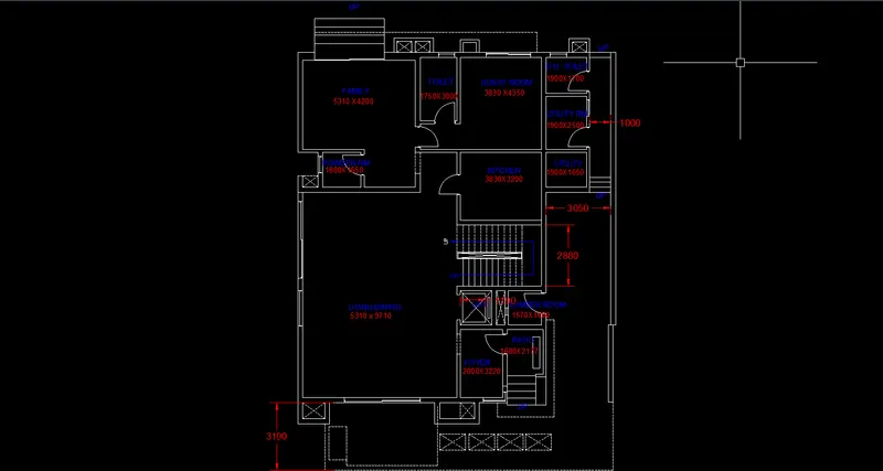
(2)AIM :Draw the floor plan as shown in the figure.
Introduction : we create plan of first floor building in AUTOCAD . we provide screenshots of every steps.we are using decimal,architectural and engineering units as required in plan. we use proper layers to show the dimension and text of elements. use wall thickness 230mm and 150 mm and door and window size are assumed.
Procedure :
- first choose units and limits before creating any figure.
-
for units, Type command - "UN"
for limits, Type command - "LIM"
- Start with vertical and horizontal x line to create corner of plan and after that offset of this line to 230mm and trim line that is not used.Now offsetting as per size of internal room of line.Using this procedure offset,trim extend and fillet whole plan is draw without any opening.
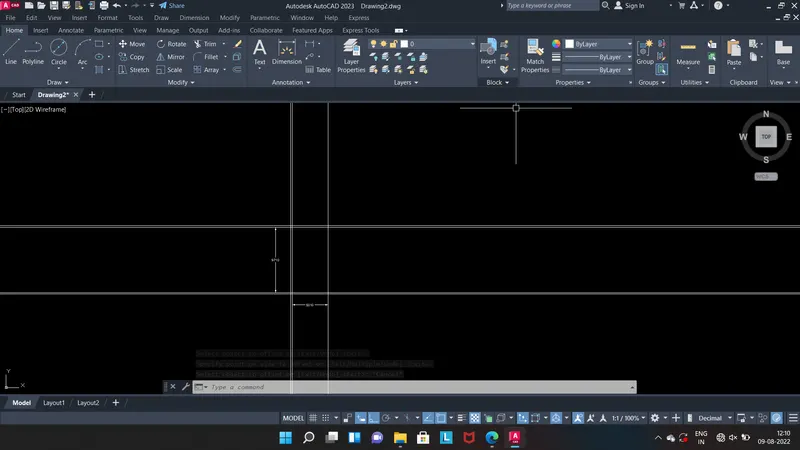
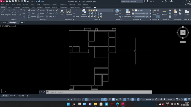
- now first create block for door and window and make it dynamic with scaling and fliping action and after that positing the door and window as per requirment.
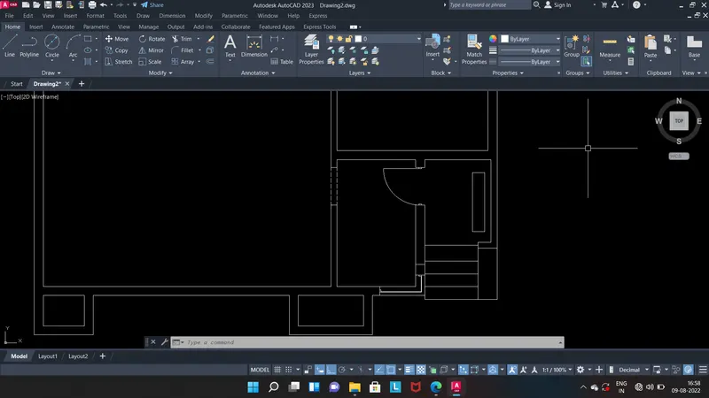
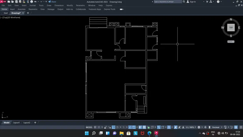
also create staircase
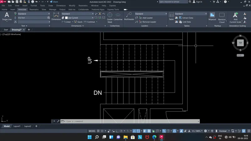
- after creating all components and now use proper dimensions and text
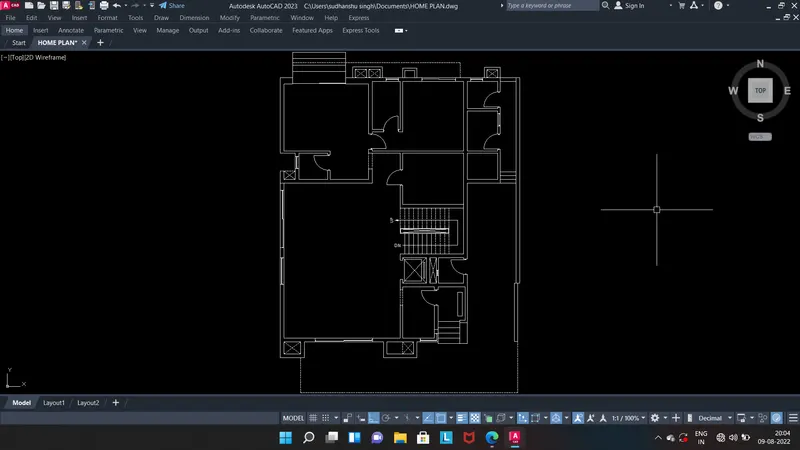
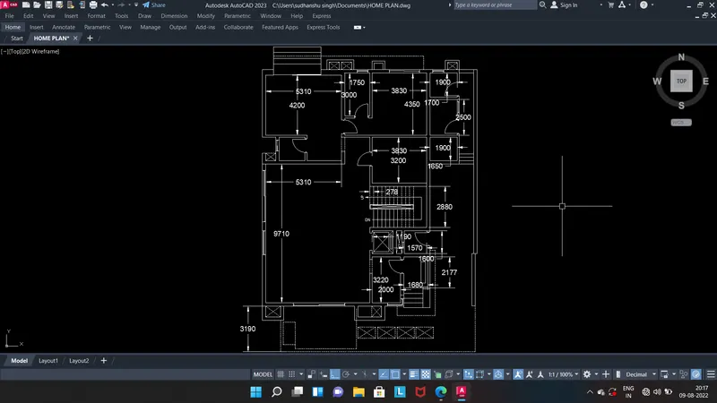
Final Result:
(3)AIM :Draw a kitchen layout
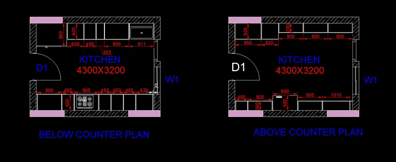
Introduction : we create kitchen layout in AUTOCAD . we provide screenshots of every steps.we are using decimal,architectural and engineering units as required in plan. we use proper layers to show the dimension and text of elements. use wall thickness 230mm and door and window size are assumed.
Procedure :
- first choose units and limits before creating any figure.
-
for units, Type command - "UN"
for limits, Type command - "LIM"
- First create below counter plan and we use line,fillet,offset command. set the dimension size using 'D' command and use door or window block used previously.
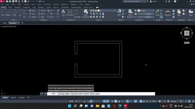
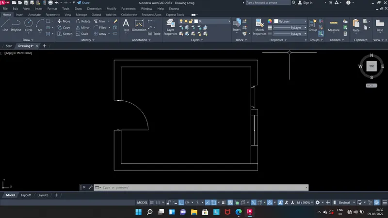
- for section part we use hatching and design center is used to get some default kitchen blocks such as refrigerator, wash basing etc.
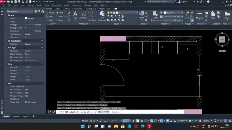
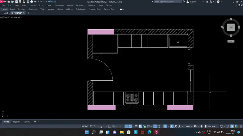
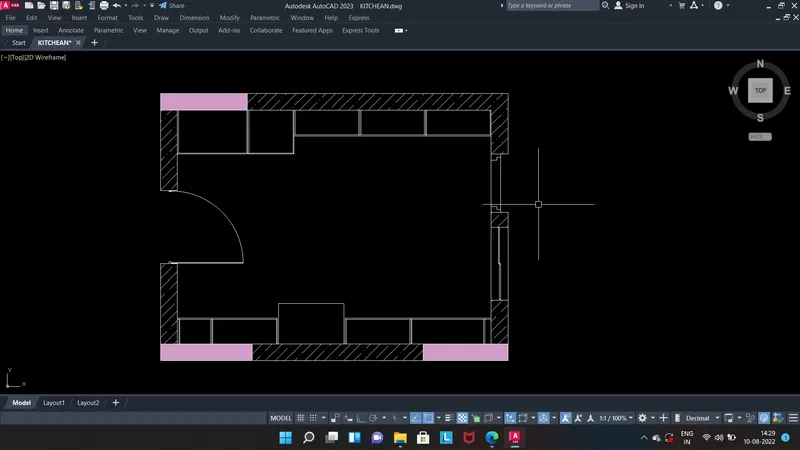
- now copy this lower counter plan and paste it and make some changes as per drawing
- now dimensioning the both plan and layer on of the both text and dimension:
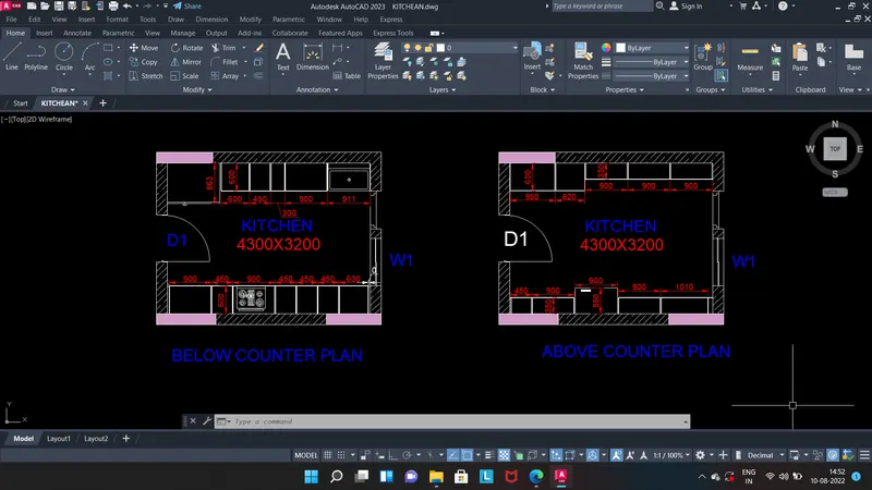
FINAL RESULT :
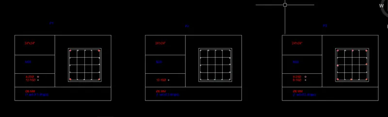
(4)AIM :Draw the column schedule as shown in the figure.
Introduction : we create a column schedule in AUTOCAD . we provide screenshots of every steps.we are using decimal,architectural and engineering units as required in plan. we use proper layers to show the dimension and text of elements. use 8mm,16mm and 25mm bar size and box dimension is assumed.
Procedure :
- first choose units and limits before creating any figure.
-
for units, Type command - "UN"
for limits, Type command - "LIM"
- first create a wire mess using line and offset command
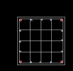
- after that create box of assumed size and text mess property and mentioned no. of bar used and name of column.
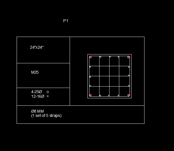
Final Result:
(5)AIM :Draw the Raft Layout as shown in the figure.
Introduction : we create raft layout in AUTOCAD . we provide screenshots of every steps.we are using decimal,architectural and engineering units as required in plan. we use proper layers to show the dimension and text of elements. Assume the size of column are 24"x24",9"x24",9"x18" .
Procedure :
- first choose units and limits before creating any figure.
-
for units, Type command - "UN"
for limits, Type command - "LIM"
- first create grid line using xline and offset command and after offseting use trim command to trim unnecessary line.Line should be dotted to represent grid line.
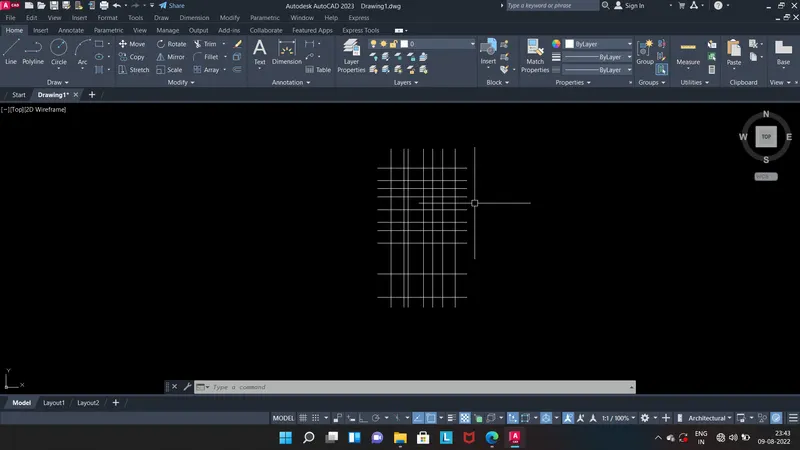
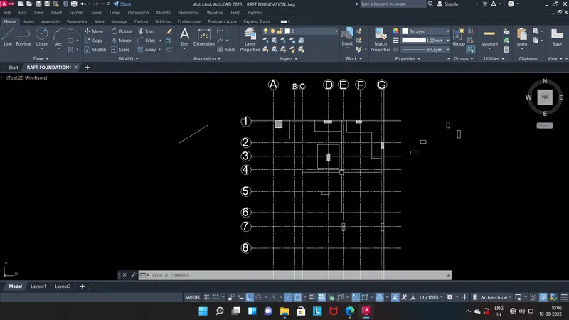
- After that start positing column according to grid number example (1,A) where column is 24"x24".
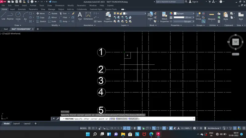
- Now draw the plan of footing according to column position.
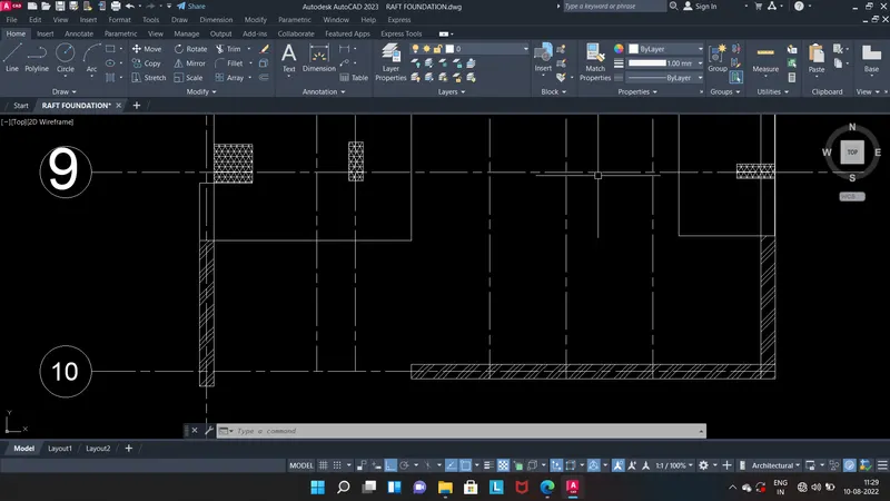
- use hatch to show the column part,concrete and brickwork
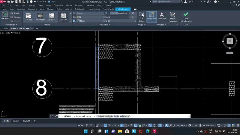
- now dimensioning the plan and layer on
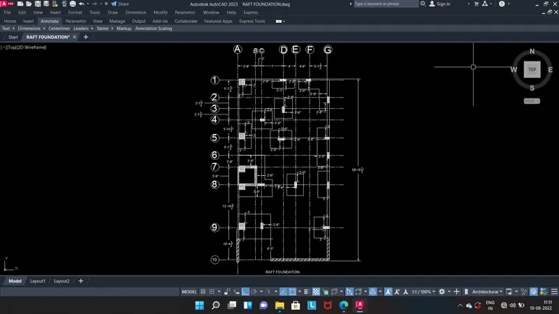
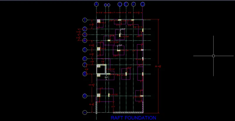
Final Result:
THANK YOU.