Creating a Wardrobe detailed drawing, Floor Plan, Kitchen Layout and Column Detail using AutoCad
Q1.
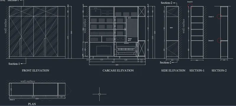
AIM : Draw the elevation and details of a wardrobe as shown in the Figure below.
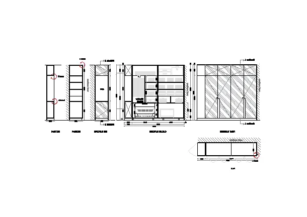
INTRODUCTION: we have drawn wardrobe diagram in autocad.we have provided dimensions ,text with the use of layers, proper dimensions text style. all dimensions are provided with MM and assumed some dimensions.
PROCEDURE :
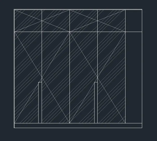
digram-1
step-1 :
- type UN for unit command and set unit to mm.
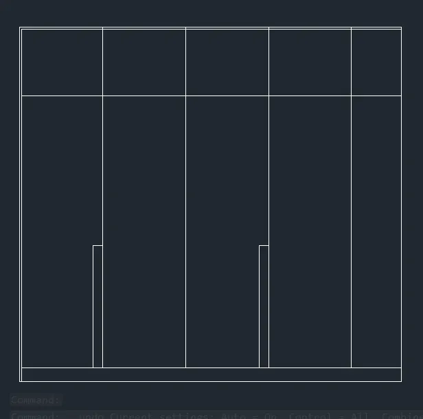
-type rec for rectangle, specify first corner point and then dimensions length=2800 and width= 2600
- type explode command and explode the rectangle.
- type offset command
- make offset of 12 from top line
- make offset of 488 from top line
- make offset of 100 from bottom line
- make offset of 365 from right side line
- make offset of 608.75, continue the offset two times
- make offset of 70 for two lines i.e line no.3 and 5 from left side and take height of 900.
- using trim command erase unwanted lines.
step-2 :
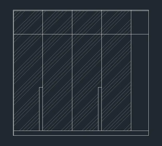
- use hatch command, select ANSI34 pattern and adjust the scale to 17
- make transperency to 80
- hatch the diagram as shown in figure
step-3 :
- type line command
- make line transperancy to 65
- connect the line as shown below
step-4:
- use hatch command again make hatch at line which is at left side.
- go to layer
- make layer name it as 'text'
- make layer name as 'dimensions'
- use dimstyle command for dimensions modification.
- give dimensions properly
- use qleader command for highlight the section-1 text
- for wall surface text either change the colour to grey or adjust transperancy.
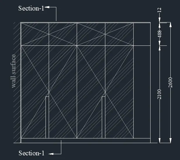
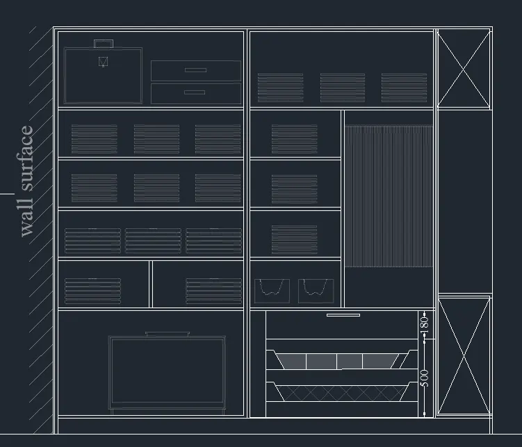
diagram-2.
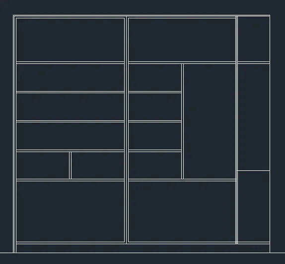
step-1 :
- type rec command and make rectangle
- dimensions- length=2800, width=2600
- use explode command and explode the rectangle.
- use offset command
- make offset of 12mm from top line and then 20mm offset then 300 offset, then 20mm offset, then300mm offset,20mm offset then 300 offset, then 20mm offset, then300mm offset.
- then make offset of 488 mm
- then make offset of 1280
- then mae offset of 720 and then 100
- make offset for vertical line from left side
- make first offset of 12mm and then 20mm and then 1223 and then 1200 and then365
- further use offset by taking reference of given diagram and make it.
- use trim command to erase unwanted line.
step-2 :
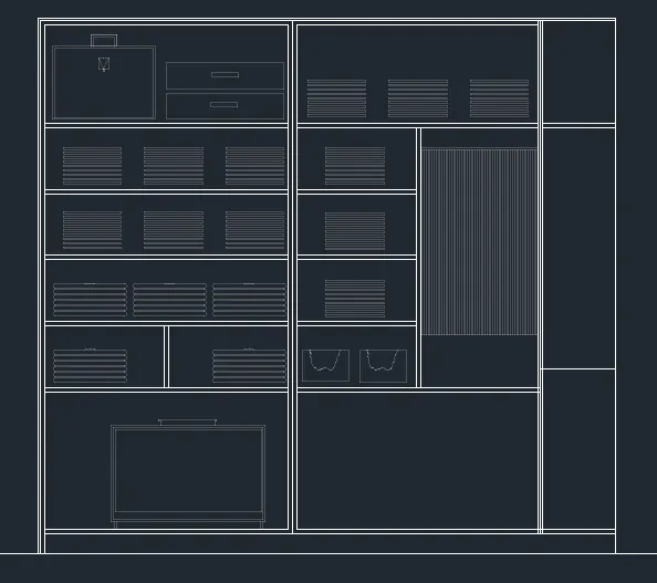
- make layer having name 'transperant line 80'
- use layer command having line transperancy 80
- make the object in wardrobe
- use line command to draw it, use array, trim offset, hatch option and copy it.
step-3
- now on right side we need to draw cross line and some offset lines
- type line command and draw it properly
- on left side using hatch and text draw war surface
step-4 :
- use layer and give proper dimensions and write text
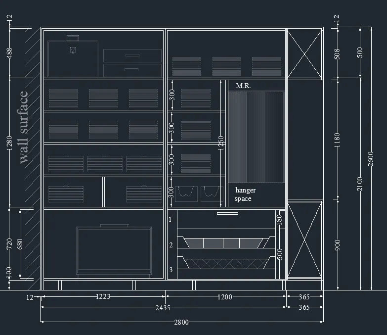
diagram 3.
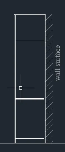
step-1 :
- type line command -
- make vertical line of 2600 length
- make offset of this line at a distance of 630
- make offset of 20 to both the vertical line from inside.
- join it with horizontal lines
- draw horizontal offset from bottom line
- make offset of distance 100 to top
- make offset of distance 900 to top , make offset to same line to bottom at distance of 20
- make offset of distance 1180 and then offfset of 520 to top.
- using hatch and text make wall surface
step-2:
- using layers give proper dimensions and text name to diagram
- use qleader for arrow showing section-2
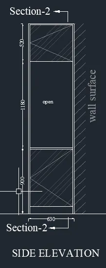
diagram-4
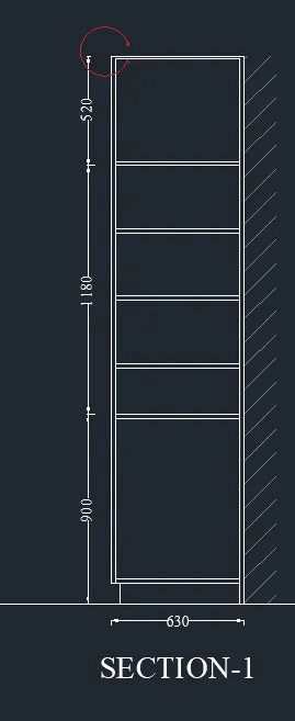
step-1:
- type line command
- make vertical line of 2600 length
- make offset of this line at a distance of 630
- make offset of 20 to both the vertical line from inside.
- connect both the vertical line with horizontal line at top and bottom
- make offfset off top horizontal line which is at 12,then500,then20,then300,then20, then300,then20,then300,then20
- make offset of 900 from bottom most horizontal line
- using hatch and text make wall surface
- using layers and dimlin command give proper dimensions
- type line command
- make vertical line of 2600 length
- make offset of this line at a distance of 365
- make offset of 12 to right sided vertical line
- connect both the vertical line with horizontal line at top and bottom
- use offset and trim command do furhter procedure.
RESULT :
thus, we Draw the elevation and details of a wardrobe as shown in the Figure below.
Q2.
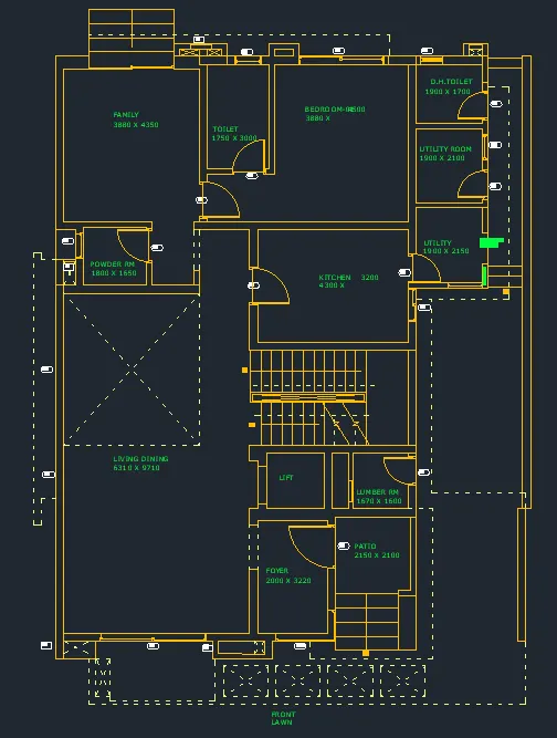
AIM : Draw the floor plan as shown in the Figure. Use the proper drafting tools to sketch the plan.
INTRODUCTION :
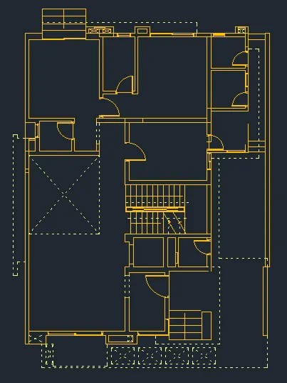
We have imported the Floor_Plan.pdf into our current drawing and started working on the project. we used scale the imported pdf file using reference option. All dimensions have taken in mm.
- Walls (Exterior and Interior)
Wall Thickness: Exterior Wall- 230mm, Interior Wall: 150 mm (Wherever Required)
- Doors and Windows: Assume the size of the doors and window.
2.1 Stairs: Tread-300mm, Riser-150mm
- Insert Text wherever required
- Insert the dimensions using proper dimension techniques
PROCEDDURE :
- set unit in mm
- go to insert menu and import pdf
- scale the import file using refrence option
- make layer for whole pdf drawing and convert it into layer
- make different layer for wall,dimension etc
- typle line command tae refrence of pdf format and draw the drawing
- select dimension layer and give text to drawing wherever required
- as said in drawing no need to make component and hatches.
RESULT : we completed floor plan drawing
Q3.
AIM:
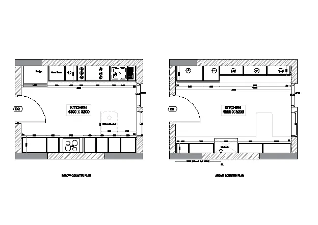
Create the Kitchen Layout as shown in the Figure below.
INTRODUCTION :
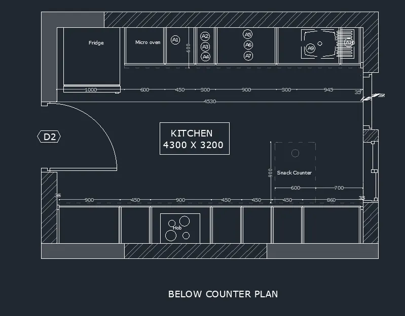
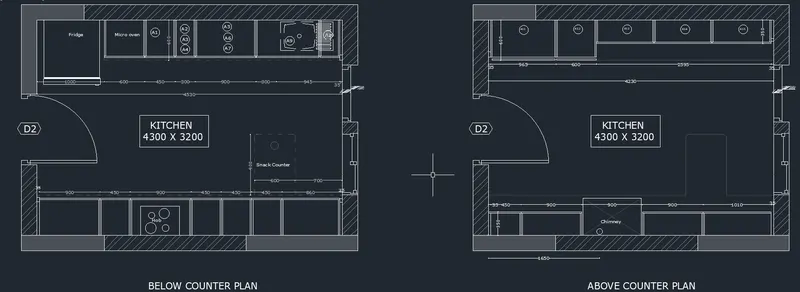
in this drawing We have sketched kitches below and above counter plan seperatly. we have used use proper dimension techniques to dimension the kitchen layout. Also, we have inserted text wherever required. All dimensions has taken in mm.
PROCEDURE :
- set units in mm
- make rect having dimensions 4300 x 3200
- take wall offset of 230mm and make offset outer side of rectangle
- use explode command and explode the fig
- make continuous offset of 4530, because we adjusting dimension the given dimension are not aacurate
- make wall offset of 230mm
- now make offset from inside walls vertically having length offset 1000,600,450,300,945,35 in continuesly toward right side of screen
- give horizontal offset of 600 to inner wall and make it dash line and reduce transperancy
- do this procedure for bottom dimensions as shown in fig
- assume some offset distance.
- use trim command to erase lines
- use hatch if you want to hatch it.
- give text using mtext command
- make rect having dimensions 4300 x 3200
- take wall offset of 230mm and make offset outer side of rectangle
- use explode command and explode the fig
- make vertical offset of distance 35, 965, 600, 2595, 35
- make horizontal offset from inner wall
- offset distance 350 and then 600 from same line
- see the given fig and trim to make proper component with dimensions
- use divide command to divide 2595m length line in 3 section
- assume some offset distance
- use same technique with dimension given draw bottom components
RESULT : we have sketched kitchen layout
Q4.
AIM :
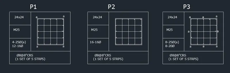
Sketch the column details as shown in Figure. Insert dimensions and text in the figure.
INTRODUCTION : detailing of column is very important in structural drawing. in this project we have setched column details.
Refer to the bar sizes from the schedule.
8mm ---- 0.31 Inches
25mm--- 1 inches
16mm—0.62 inches
PROCEDURE :
- set unit to engineering inches
- type rec for rectagle haing dimensions 24"x24"
- explode the rectangle
- make offset of 6 inches having 4 numbers in both x and y direction
- fillet the inner rectangle by giving radius
- make circle showing bar
- hatch it with solid
- make a table and paste this above drawing in it
- give tex using mtext command as given
- copy this table
- and make another drawing having different detailing
RESULT :
thus, we have sketched column details
Q5.
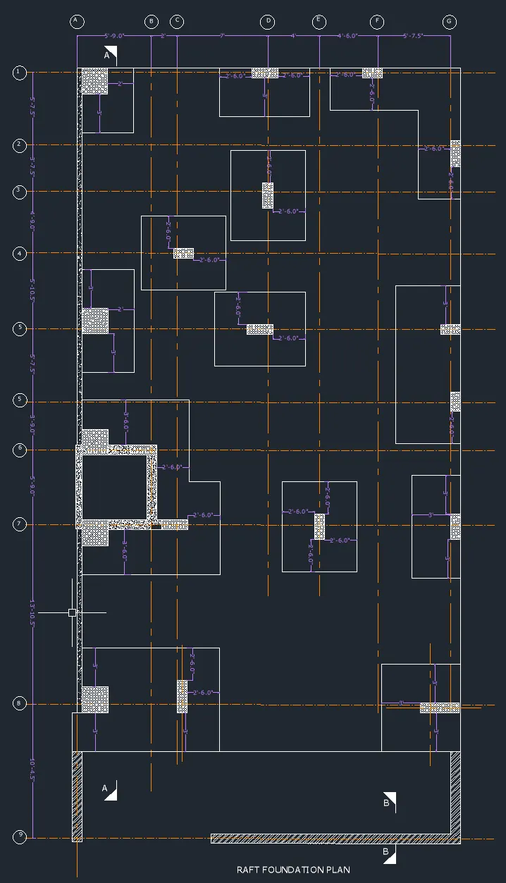
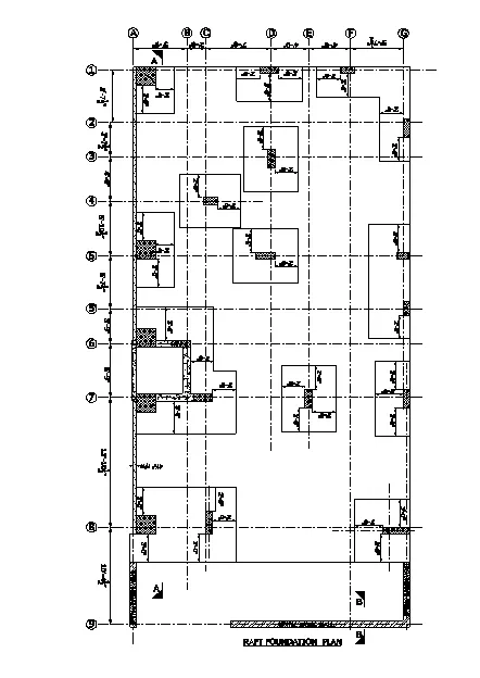
AIM : Draw the Raft Layout as shown in the Figure.
INTRODUCTION :
We have sketched raft foundation plan.Assume the column size as per your knowledge.we have taken the sizes as: 24”x24”, 9” x 24”, 9” x 18”, and 9’ x 24”. we have imported the raft_foundation.pdf to ensure the missing dimensions
PROCEURE :
- set unit to engineering inches
- draw xline in both x and y direction
- make layer of center line and select linetype centerline with different colour
- make offset to y-direction vertical line
- make first offset 5 inches
- choose layer dash line
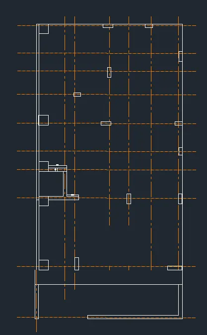
- make continuous offset towards righ side at a distance of 5'9", 2', 7, 4', 4'6", 5'7.5"
- do this sam procdure for x- dirction x line
- give offse of 5'7.5", 3'7.5", 4'9.0", 5'10.5",5'7.5",3'9",5'9", 13'10.5",10'4.5"
- for column position reference needed
- import pdf file as given and scale it by giving reference
- convert this pdf into layer having different colour
- paste this layer pdf into our acual drawing
- mark the column position
- make layer for dimensions
- hatch command used wherever hatching needed.
- finally using dimlin and mtext give dimensions and text
RESULT :
we have drawn the raft layout