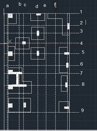
Creating a Wardrobe detailed drawing, Floor Plan, Kitchen Layout and Column Detail using AutoCad
aim to draw elevation and details of a wardrobe
1 open autocad
2 go to the home tab and take a new sheet by selecting the new option
3 give the command units and set the units in mm
4 set the limits from 0,0
5 draw a lne of 2800 in x directo
6 leavve a space of 365 frm the rightsside
7 and devide the remaining part into 2 peces
8 now put the crecer on the left side of line and give a height of 630
9 the lines will form a rec
10 now select offset option and give offset of 20 to all lines as deatil
11 now leave some distance ad go to snap setting and mark extention and end poits
12 draw a line from the extention use of same l = 2800
13 now give the height 2588
14 from the right side leave a distance of 365 and deaw a line
15 now devide the remaing part into 4 rec aand leave a distance of 488 from upper borderline a draw a offset
16 now take the line and do the criss cross with the help of snap
17 join the opposite corners
18 now go to the hatch and select a lining hatch and select the ections you want too hatch
19 frount elivation will be formed
20 now to draw carecase elivation leave some gao and draw a rec of 2800,2600
21 now draw a offset ata distance iof 680
22 now draw 4 offsets from that line of 300
23 and then draw a line oof 508
24 in wridth draw a offset of 1223 from left
25 now draw a offset of 365 from the right corner
26 trim and cut the unwantd line at proper dimentons the second diagram is done
27 draw a offset of 20 at everline
28 to draw the section 2 draw a rec of 630 ,3100
29 divide it into 3 sections as per the dimentions 900 ,1100,520
30 do the hath comand and do the hatching for top andbottom part
31 now draw 2 rec of 630,3100 365,3100 and divide it into parts
32 use mtext to write the given text at locations
33 result 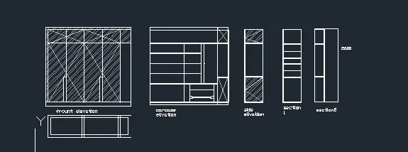
b aim to Draw the floor plan as shown in the fig
1
Walls (Exterior and Interior)
Wall Thickness: Exterior Wall- 230mm, Interior Wall: 150 mm (Wherever Required)
- Doors and Windows: Assume the size of the doors and window.
2.1 Stairs: Tread-300mm, Riser-150mm
3 draw a rec of 11360 ,15710 and give the offset of 230 to make a externall wall
4 now from the top give a off set of 4350 to make the family room wall
5 now select the left ex wall and give a offst of 3380
6 go to trim commandndtrim the remaining parts
7 now from thhe right family wall give a offset of 1750 to make toilet wall then give a offset to make internall wall 150
8 now from this wal give a offset pf 3830 to makr the bdedroom wall and wall thickness is 150
9 now lat give a offset of 1900 to make the utility room ad wll thickness is 230
10 now select the toilet wall at any distance and make a door with the help of creating a rec of any lenght and now go to arc
11 select the arc start center direction and make a door
now make a door with the same process which goes out from the bedroom
12 now from the bedroom wall give aoffset of 1650
13 the breadth of the room is 1650
14 now from the upper bedroom wall give a offset of 3200
to mae a ktchen
after the kitchen draw the steps wwith the help off the offset command
draw a line and give a offset of 150 to mae steps contineu the proces untill steps aremade
15 now draw a wall of 150 mm at rthe end ogf the steps
16 dtaw another wall any distance and draw a square in between to make it alift
17 now the right side of the lift there is a room lumber room whichh has the dimentionn 1570 /1600
18 from the walll of the lift give a offset ata distance of 3220 to make foyer area room
19 build 5 steps at the start of patio room
20 use the trimm command to trimm te unwanted lines
21 use mtext to write the text when needed
22 result 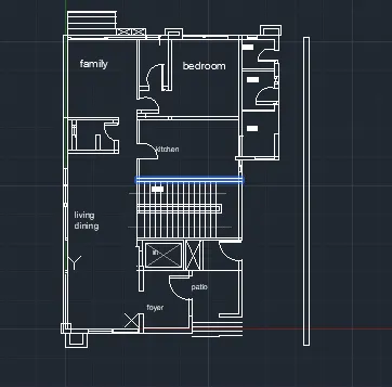
c aim to . Create the Kitchen Layout
1 open autocad
2 select a new sheet
3 select the units
4 now set the limits
5 draw a rec with the dimentions of 4300/3200
6 now give the offset command and make the ecternall wall tickness 300left prt
7 now cut the left part of the rec to make a door
8 select line command and draw the section where the door iss fixed
9 now draw a rec of sml breath and any length
10 now go to arc from the ribbon and select arc
11 select 2 points and give the direction
12 to make a door
13 now draw lines to make the exwall i to diffrent sections
14 now use the hatch command and select any hatch
15 now select the scale of the hatch to 500
16 ow click on the areas you want to hatch
17 now draw a small rec of 35 and placeit t a h of 600
18 now draw a line of 600 and join it to thre rec now give offset of thaat line at 900 ,450 ,900,450,450,450,510
19 give ofset of 20 to each line to makedeatils
20 now with the help of mtext write the text
result 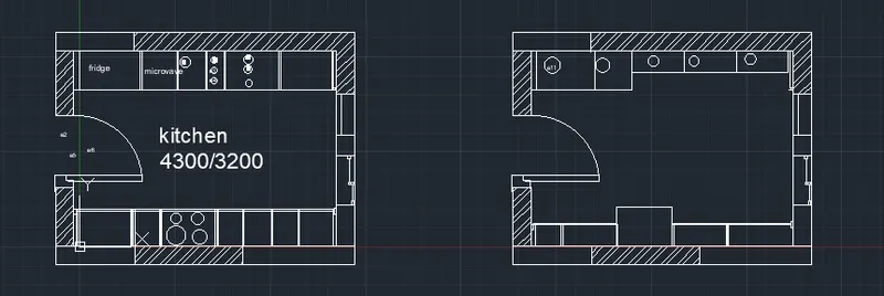
d aim Sketch the column details
8mm ---- 0.31 Inches
25mm--- 1 inches
16mm—0.62 inches
1 open autocad
2 select new sheet from the ribbon
3 set the units
4 set the limits
5 slect the rec option and make a rec of any section
6 select the copy optio and make 2 more rec
7 now with the help of the line mke the sections in the rec as shown
8 now use mtext comand and give the height of the text and write the text
9 result 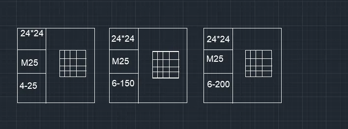
e aim to . Draw the Raft Layout as shown
1 procedure open autocad
2 select a new sheet
3 now select the units
4 then set limits from 0,0
5 now selectthe line
6 then go to the line type command and select line small dah line and set current
7 use thre current line to make 10 lines at diffrent distances
8 now use the line to make 7 vertical lines at spesific dimentions as shown in the question
9 now takea rec of 9/18 and put it at the places were rec is reired with proper measurment
10 now make a small rec and place it at the center of the rec
11 now use the commmand hatch and hatch the small rec at center
12 use copy and move options to make coloums where it is recquired
13 use mtext commnd
14 set the height of the text
15 set the rotation angle of te text
16 result