Creating a Wardrobe detailed drawing, Floor Plan, Kitchen Layout and Column Detail using AutoCad
1. Aim and Introduction:
Aim
This challenge aims to provide the neccessary experience of an engineer in the drawing of plans using the autocad software. It give the urge to expand their knowledge whilevmanipulating the different tools provided in the software.By utilizing the tools, any plan or drawing will be provided with ease. This challenge aims to allow the student to show all the things they have learned throught the videos.
Introduction
The AutoCAD software provides different tools.The tools used in the this challenge is as described below:
Line- creates line object
Polyline- creates rectangle line object
Rectangle- creates rectangles object
Circle- create circle object
Trim-Cut unwanted lines or shapes with the provided cutting edges
Extended- Extend lines to opposite corners
Move- Move objects to particular locations
Copy- Copy obejects to particular locations
Rotate- Rotate selected objects to a particular angle with respect to base point
Array- Copy an object in a set path linearly or polarly
Join- Joins separated line objects to a particular angle with respect to base point
Dimlinear(DLI)- provides vertical or horizontal linear/ straight dimensions
Dimligned(DAL)- Provides dimensions with respect to the angle of the object
Dimangular(DAN)- Provides angular dimensions between two line objects.
Quicklinedimension(QDIM)-provides quick dimension of a geometry
Leader- creates an arrow head line
Layer- Provides identification of line or object groups by their properties
Units- Open "Drawings Units" window to specify to modify the dimension properties
Hatch- provides hatching pattern in a given object or internal point
2.Sketch and Procedure:
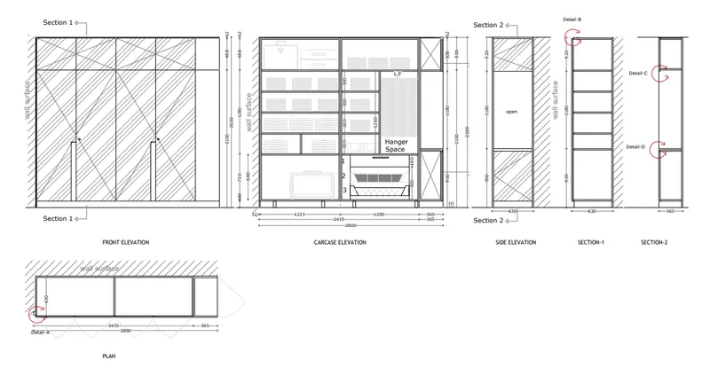
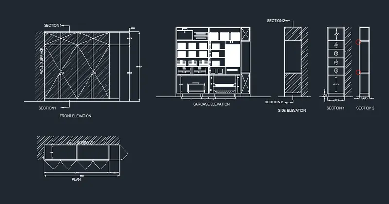
Challenge 1- 1.Draw the elevation and details of a wardrobe as shown in the Figure below. After sketching, you need to provide the dimensions and text with the use of layers. Use proper text styles and dimension methods to document it. Also, assume dimensions, whereever needed.
Note: All dimensions are in mm.
PROCEDURE:
First, sketch the plan. Detail marks will be provided after the sketches are done
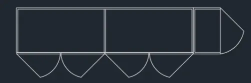
- Create a rectangle 365 x 630 in dimensions
- Offset the object inside by 20mm
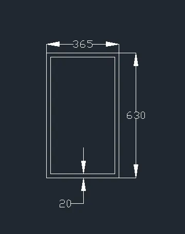
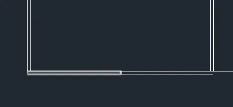
- Trim the right line of the inside rectangle and extend the lines to the right
- Make a another rectangle with 2435 x 610 dimension using the upper left corner as a base point
- offset the inner left and right line inside by 1170mm

- Create a rec object the lower left corner as base point with 600 x 20mm dimensions. Move this rectagle 5mm to the right. copy the rectangle object to the midpoint of the line above. then move 5mm to the left
- Make a 45 degree line from the left corner of the rec. lenght of line 450mm. and convert second line to "ARC" and mirror this poyline object to the right and move it to the enpoint of the rec on right.
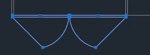
- Do the same technique to sketch the on the right side.
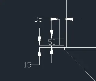
- Add the rectangle on the left side. Use th rectangle tool and react a rectangle object with 35x50mm dimension. Use the lower left corner as base point.Move it 15mm upward
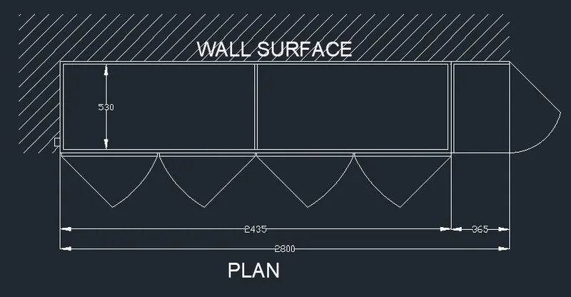
- Create a boundary polyline object the top and left of the sketch. Create the hatch tool and click "Select object" as the option.Delete the polyline object after creating the hatch. Use the DText tool to add the required texts on the sketch.Use Dimlinear tool to add the dimensions required
Proceed to the Front Elevation.Use the polar snapping tool to align the plan drawing with the front elevation drawing
- Draw the base line, use line command to draw a staright horizontal line at the top of the plan and draw rec 2800x2600
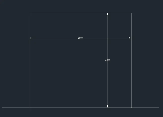
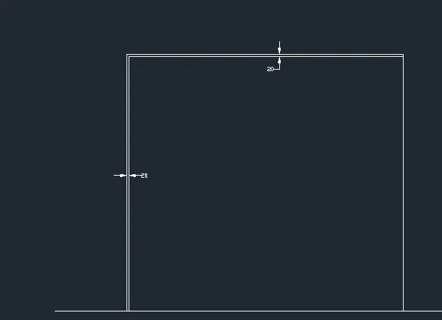
- offset the left line 20mm inside. then offset top line 12mm inside
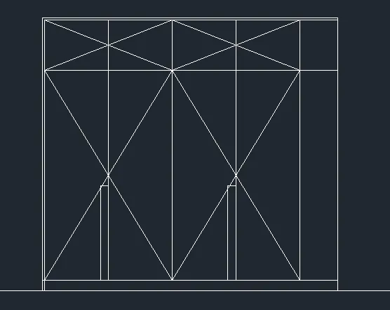
- The n divide th middle sopace into 4 spaces and make a line to divide the spaces. 2423/4=605.75mm.ofset the topline by 5oomm and bottom line by 100 upward the nconnect corners by a line creating an x image. Create rec below use rec tool and specify the lower right corner as base point dimensions are 75x900.
- Create a rectangle object as hatch boundary. Add the dimensions on the side. Use the Dimlinear command, and add the text.
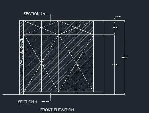
Proceed to the carcase elevation. use polar snapping tool to align the front elevation
- Copy the bounadry line of the front elevation
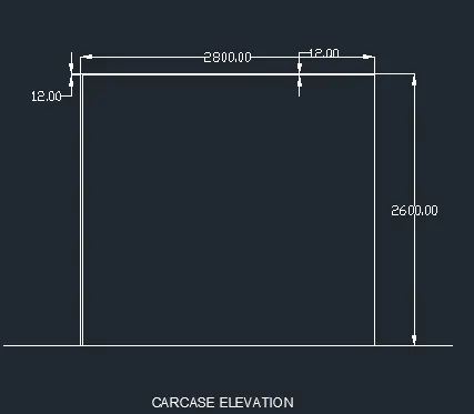
- Offset theright line by 365mm to the left. the offset the created line by 1200 to the left
- Offset the bottom line 100mm up.Trim the unneccessary line
- Offset the lines by 20mm to create the inside boundary
- trim the unnecessary lines
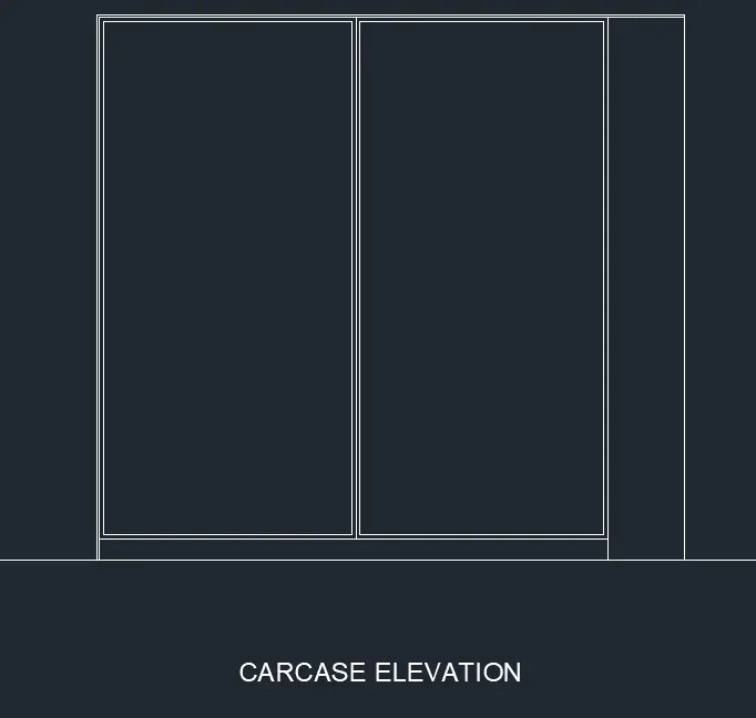
- Create the inside of the rectangles. Proceed with the right inside rectangle first
- Offset the top line downward by 488mm downward. Then offset the created line by 1260mm downward
- and again offset the latest created line by 22mm downward
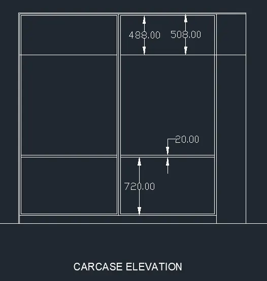
- Proceed with the top layer. Offset thebottom line by 20mm upward
- Create the objects inside using the rectangle tool,copy tool, and move tool.Proceeed to the 2nd layer. offset top line by 300 downward then proceed by 20mm downward. do this again 3 more times. The same procedure goes with the on the other side
- Add the dimensions and texts using the dtext and dimlinear command
- Also, copy the hatch and text "wall surface" from the front elevation to the carcase elevation
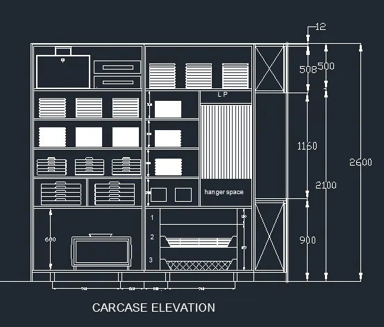
Proceed with the side elevation
- Create a line as a baselinear. Make sure it aligned with the other elevations
- Craete a rectangle with 630x2600 dimensions
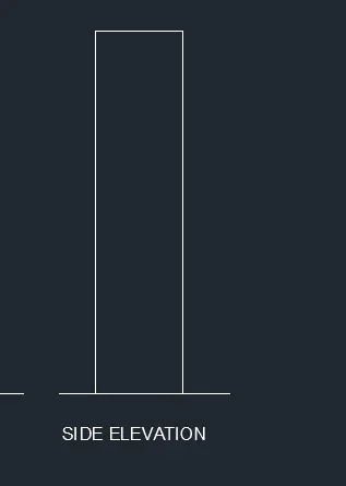
- Explode the rectangles and offset the followings sides inside. Left=20mm, top=20mm, right=20mm, and bottom=100mm. Trim the unnecessary lines.Offset the top line by 500mm downward. The created line by 1180. And again the created line by 40
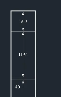
- Create a rectangles object for the spaces with hatch and add hatch pattern. Delete the rectangles after
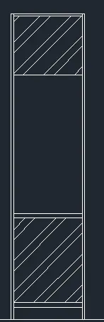
Proceed with section 1
- Create the boundary elements. Use rectangle tool and offset tool
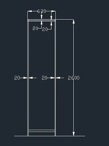
- Trim the necessary lines to form the corners
- Align the inside boxes using ray tool or xline tool
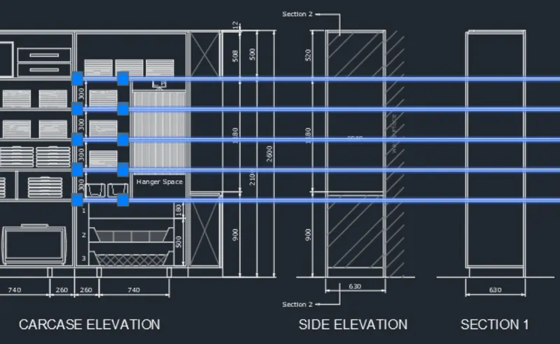
- Trim the excess lines.Cretae the bottom part. Use offset, trim and line tool and add the dimensions and finish se tion 1
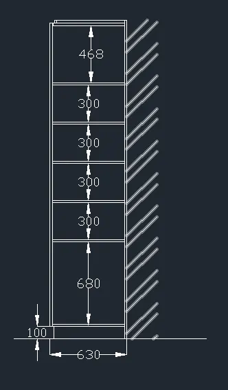
Proceed with section 2
- Create boundary elements
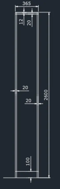
- Trim an fillet the lines. Trace the lines from the carcase elevation
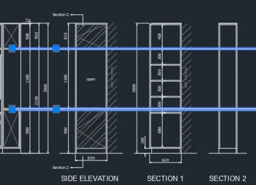
Create the detail mark
- Create a line as below.Angeled with 30degrees
- Then add teh angular dimension using dimangular
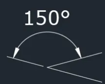
Result:
B. SKETCH 2 - FLOOR PLAN
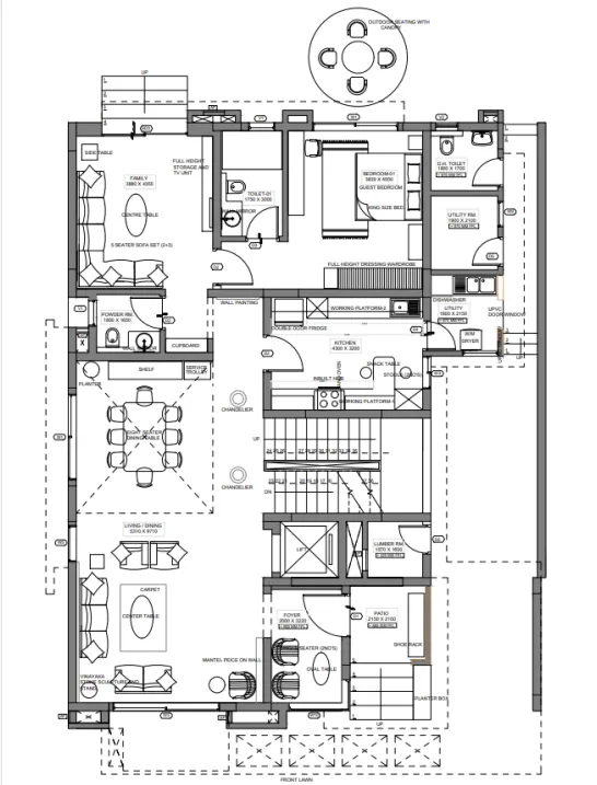
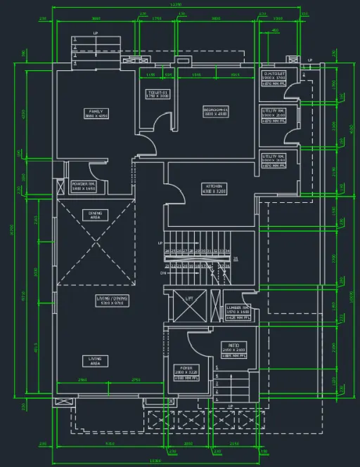
CHALLENGE 2-Draw the floor plan as shown in the Figure. Use the proper drafting tools to sketch the plan. Do not hatch or draw the furniture. You need to draw the floor plan with the following:
Note: You can also import the Floor_Plan.pdf into your current drawing and start working on the project. You need to scale the imported pdf file using reference option. All dimensions are in mm.
- Walls (Exterior and Interior)
Wall Thickness: Exterior Wall- 230mm, Interior Wall: 150 mm (Wherever Required)
- Doors and Windows: Assume the size of the doors and window.
2.1 Stairs: Tread-300mm, Riser-150mm
- Insert Text wherever required
- Insert the dimensions using proper dimension techniques
Procedure:
- Use xline command to create teh inner corner boundary. Start from the top left corner

- Fillet the corner and create teh family room. Dimension 3880x4350. Use offset or copy tool
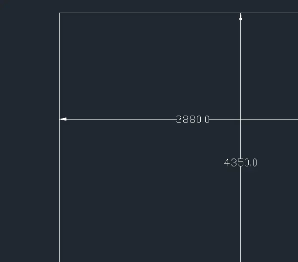
- Now you have to offset the side to create tehe walls and create the openings boundary using lines and trim to create the openings
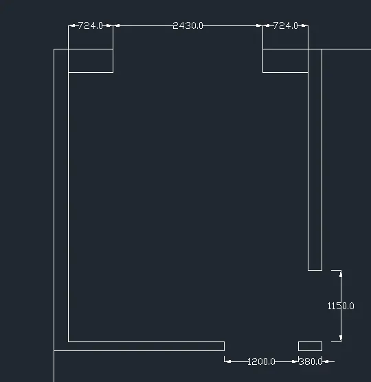
- Draaw toilet-01 area, adjust the wall thickness as per the drawing
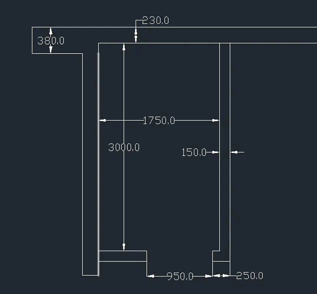
- Proceed with bedroom-01. Do the same steps as we did in the toilet and family room sketch
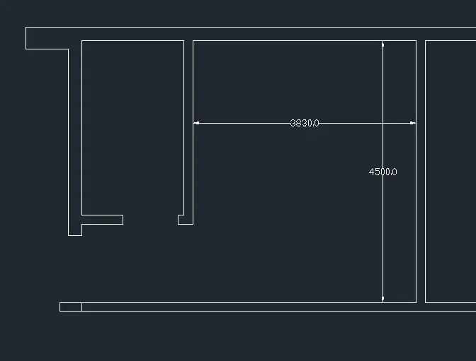
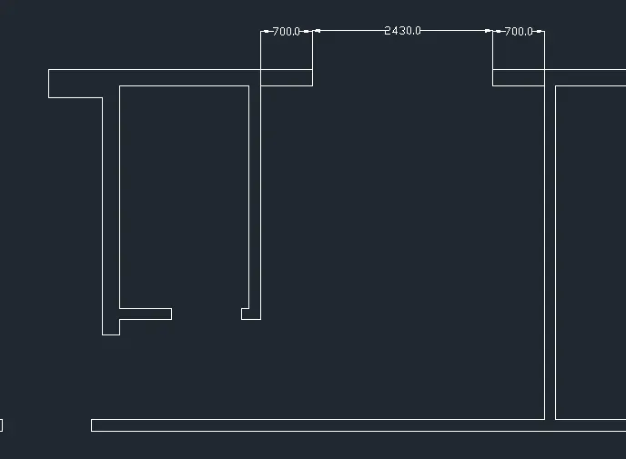
- Then using the same steps and tools used, Draw D.h Toilet including the utility room
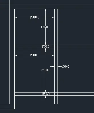
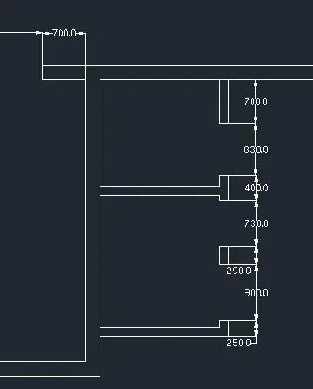
- Finish the side by drawing the utility area with the same steps
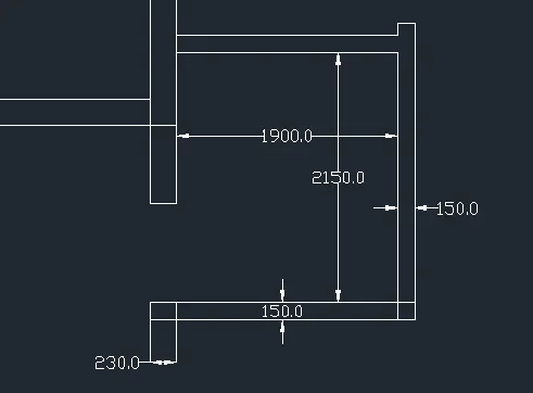
- next draw the kitchen
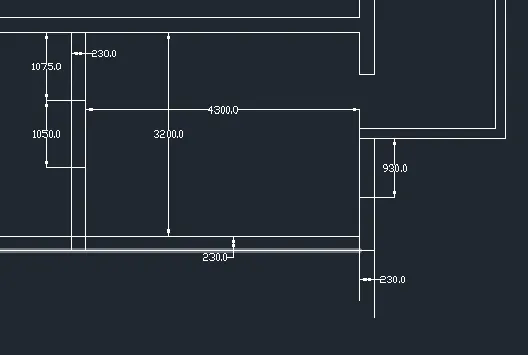
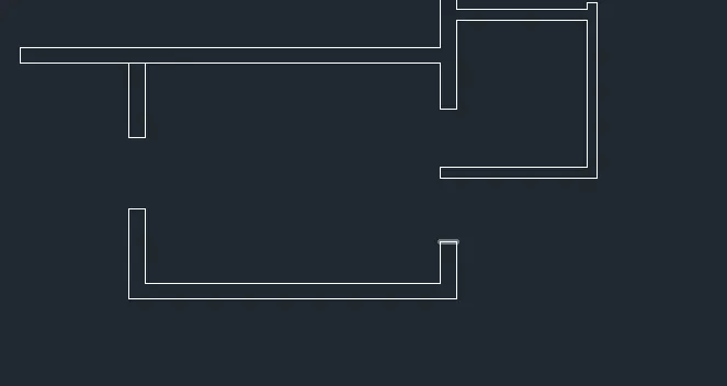
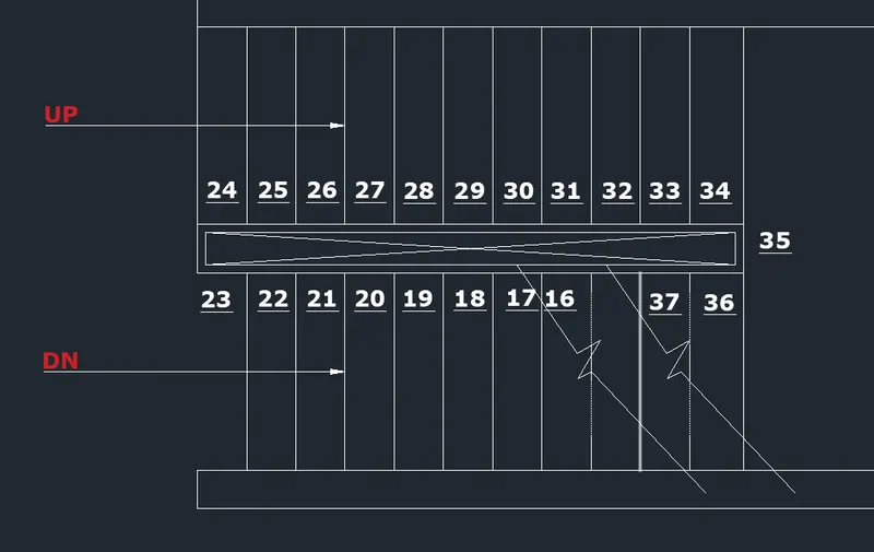
- Now create the stairs.Add a text the thread of the starirs to indicate the number of steps. Use dtext commands. Text height is assumed to be 125. Underline the text for emphasis
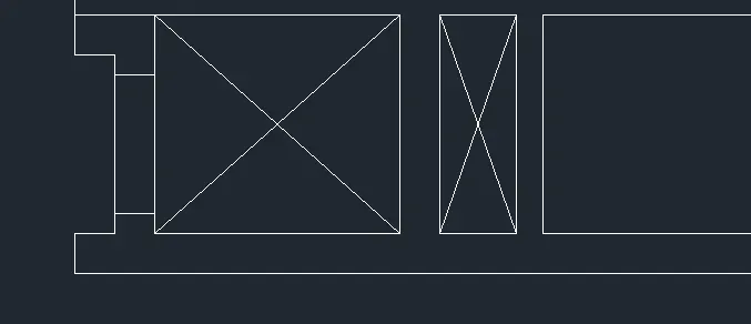
- Continue with the lumber rm and lift space
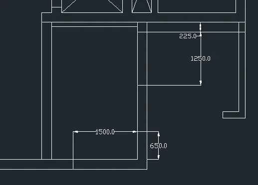
- Next is the foyer. Follow up with the patio to finish on that side
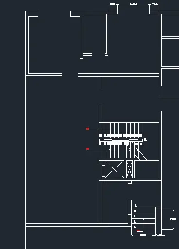
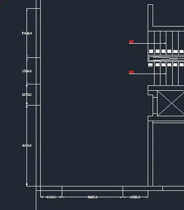
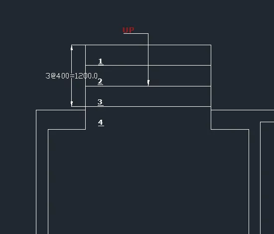
- Create the stairs after trimming the openings. Use thread=400. Add the text to indicate the step. Include the direction of the stairs
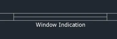
- Indicate all the windows using this sketch
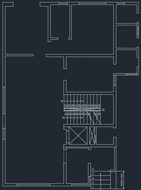
- Proceed with the powder room and finish the inside of the plan
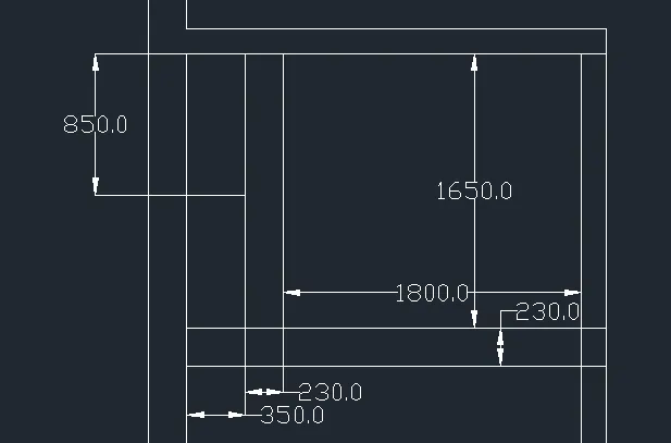
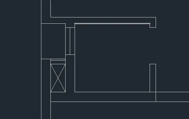
- Draw the outline of the dining table
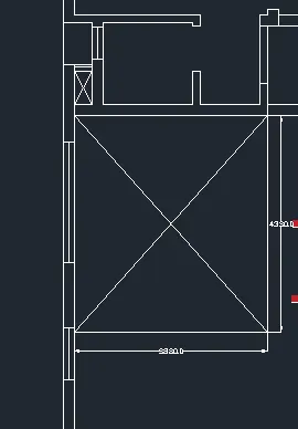
- Draw the stairs at the family room
- Draw the outside of the plan
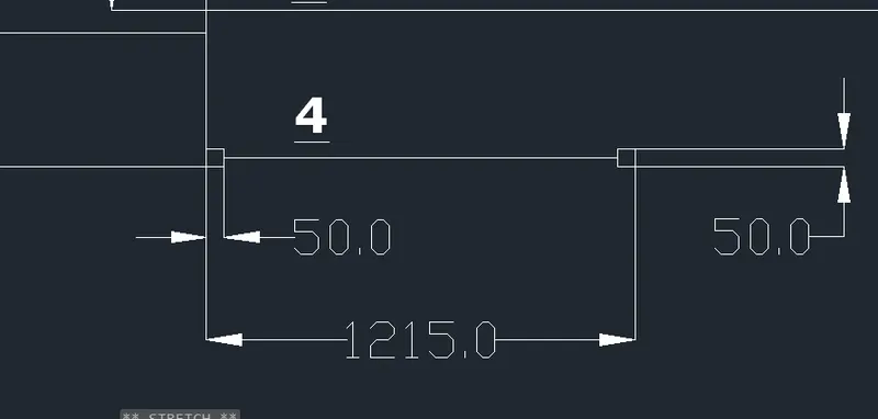
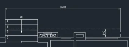
- Craete teh outside wall
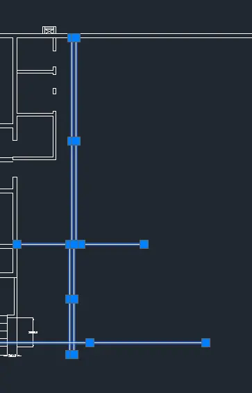
- Create the hidden lines
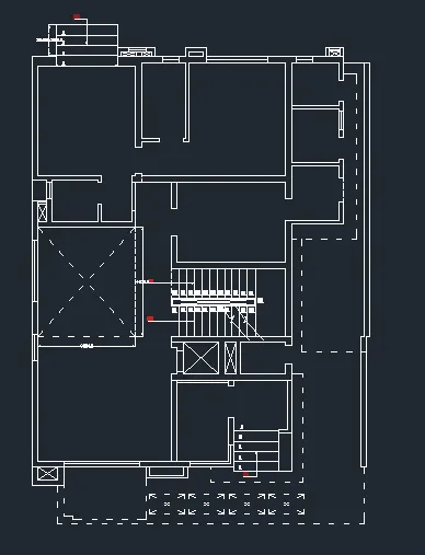
- Draw the door
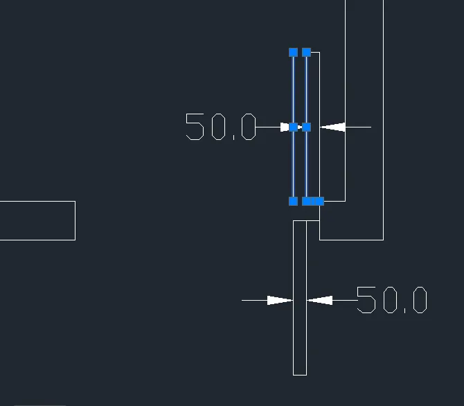
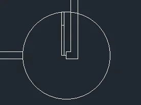
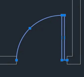
- Do this on all the door locations
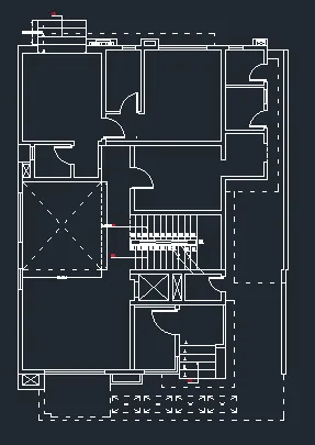
Results:
C.SKETCH 3- KITCHEN LAYOUT:
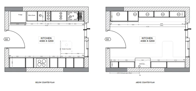
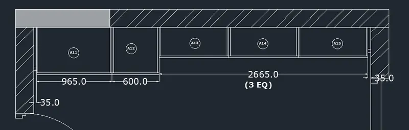
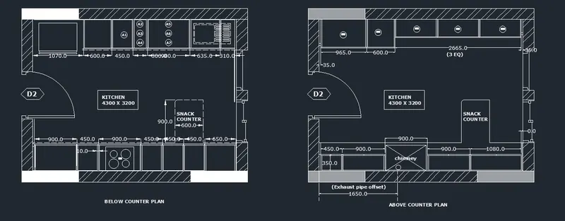
Challenge 3- Create the Kitchen Layout as shown in the Figure below. Also, use proper dimension techniques to dimension the kitchen layout. Also, insert text wherever required. All dimensions are in mm.
PROCEDURE:
Proceed with the wall, doors and windows. This image is present on both plans.
- Create teh inside boundary using rectangle command. Offset the by 230mm outside to create teh wall thickness.
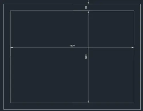
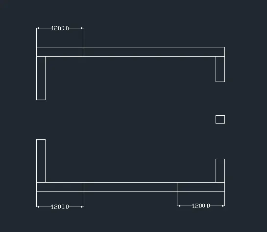
- Explode the rectangles.Offset to make the opening boundary and trim.Create the hatching boundaries
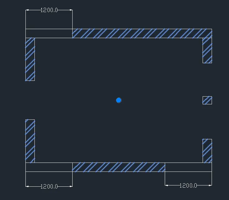
- Hatch the wall using "Pick internal points" and edit using the htach tab on top of the interface or the properties tab
- Create the door. Use polyline,rectangles and circle. Utilize mirror tool as well
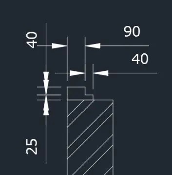
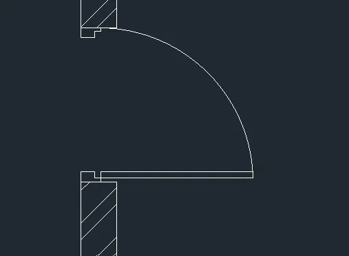
- Proceed with the window sketch.Use the same tools used in creating the door
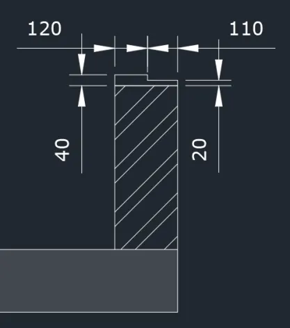
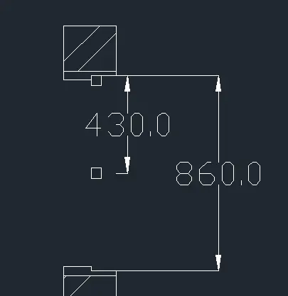
- Copy the door boundary for the 2nd window
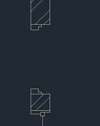
- Join the lines to close the window
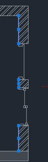
Proceed with below the counter plan
- Create lines
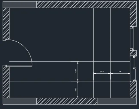
- Create the lines for the intersection.Use line and copy tool
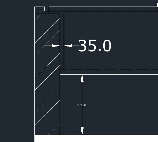
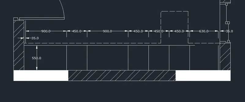
- To create dimensions,use dimlinear command and dimcontinue and dimcontinue for easy progress
- Adjustment are provided to accomodate teh 4300 inner dimension
- Offset lines to create depth.Use trim to cut unnecessary lines
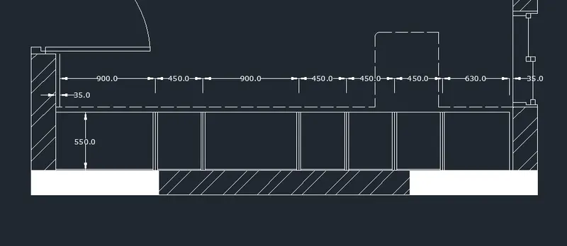
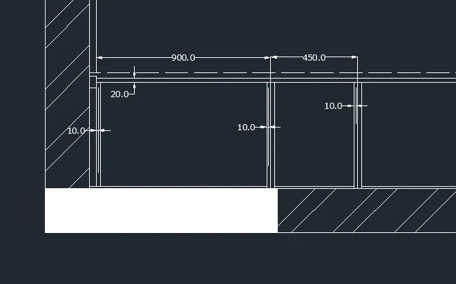
- Add the rectangle object at the corners and sketch the door using rectangle and move tool.Utilize teh sketch tool to for easy progress.Use 10mm spacing for the doors and 20mm thickness
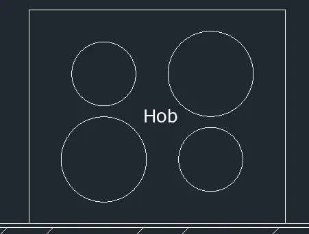
- Create the Hob sketch.Use rectangle with 600x500 dimension.Circles with diamete of 200 and 150
- Turn on geometric center in the osnap setting to check the center of the rectangle

- Use mirror with center of the rectangle as mirror plane to duplicate the objects
- Then mirror again to invert the objects
- Use dtexts to add the text object
- Proceed with the top part cretae boundary lines using line tool
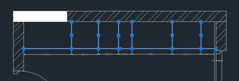
- Trim the lines and add line objects to enclose the boundaries
- Vertical line thickness is 20mm both sides.Change the outer bottom line to hidden line.Use match properties command for easy progress
- Trim unnecessary line to finish
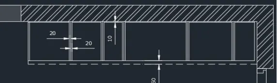
- Create the rectangle on the lower right side
- Create the doors with 20mm thickness and 10mm spacing same as thefirst one
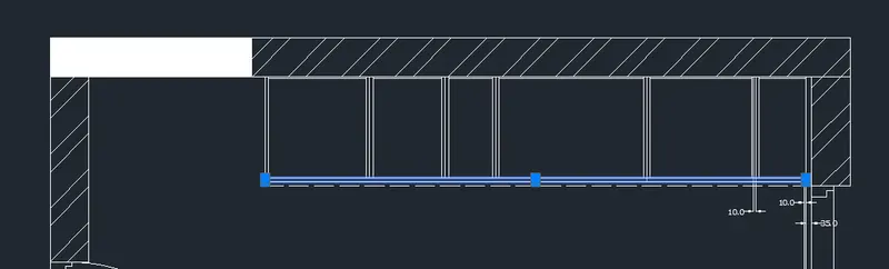
- Add the inside object using circle,rectangle,copy,text and fillet tool
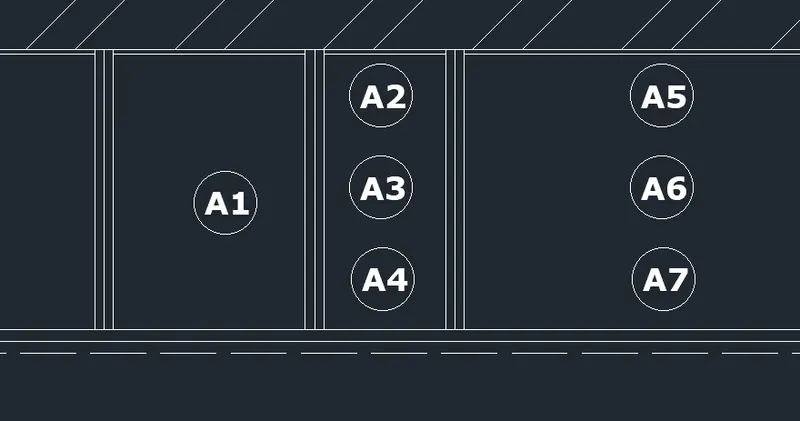
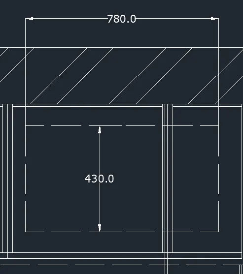
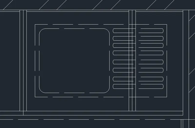
- Use rectangles and lines for the fridge object,Use circle tool as cell for the corner opening.Add the text to finish.
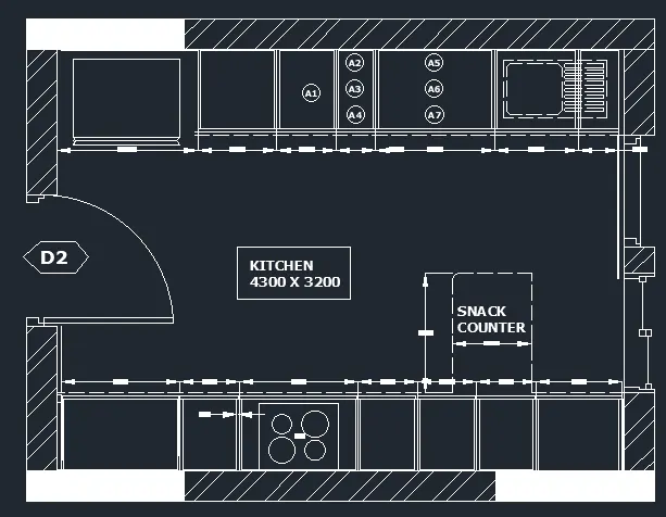
Proceed with the above counter
- Copy any relative lines from below to above plan.Change line types as appropriate
- Add the border lines for the below part.Trim the line appropriatetly
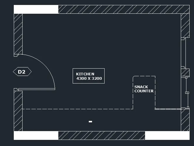
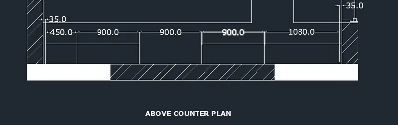
- Create the cabinet walls using offset and trim tool.Thickness is 20mm.BOttom part is 10mm.
- Trim unnecessary lines
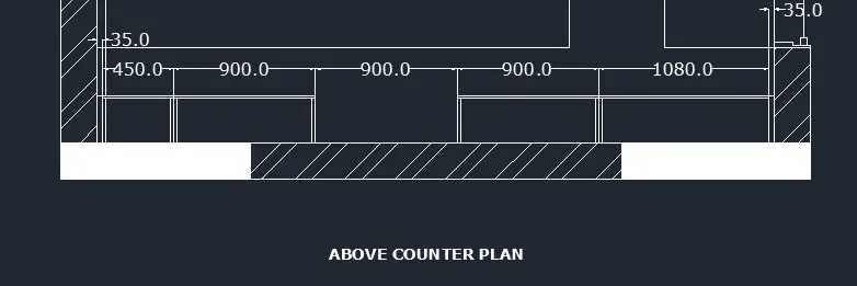
- Create teh chimney as below
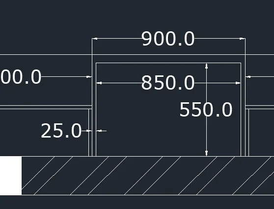
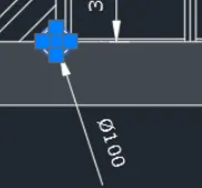
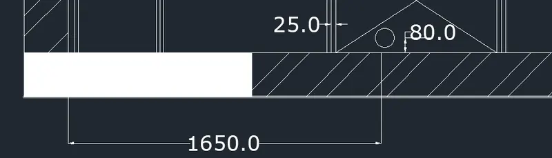
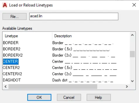
- Load centerline in the linetype manager
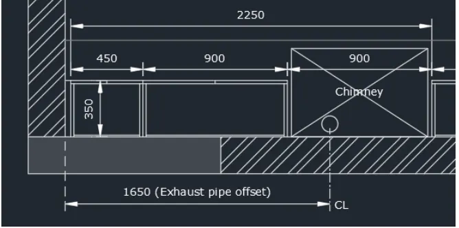
- Explode the dimension line and edit as below.Add teh appropriate texts using dtext command
- Proceed with above objects,Create boundary lines.Trim the lines appropriately
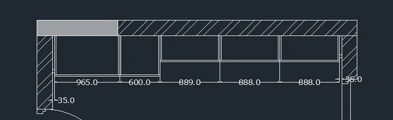
- Craeate the walls.Thickness=20mm.Use offset,copy and trim tools.Add the texts
Results:
Final product
D.SKETCH 4-COLUMN DETAILS:
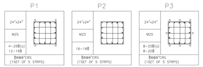
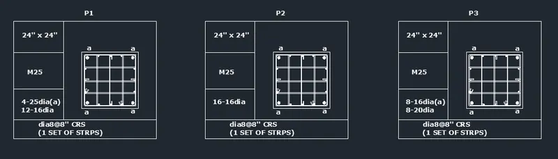
Challenge 4-Sketch the column details as shown in Figure. Insert dimensions and text in the figure. Refer to the bar sizes from the schedule.
8mm ---- 0.31 Inches
25mm--- 1 inches
16mm—0.62 inches
PROCEDURE:
Note:units are in mm
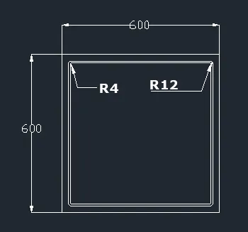
- Create PI. ceate a rectangle 600x600mm (24'x24')
- Concrete cover is 50mm.Use offset tool
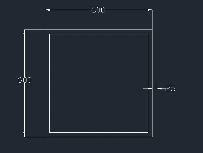
- Create stirup thickness 8mm.fillet the edges.Use fillet=4 for inside rectangle and radius=12 for outside rectangle
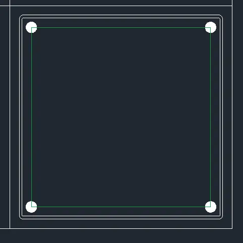
- Create teh main bar for corners. Use circle tool. Diameter=25.Move 25right and 25down HAtch with solid pattern.Mirror the circle and shade using teh midpoints as mirror plane.Draw a line between the circles for refference
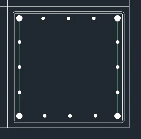
- Draw the smaller bar at the midpoint of the lines. For teh same with the 25mmdiameter bar.Copy them at equal spaces to form 3 bars.Diameter of smaller bar is 16
- draw the stirrups.Draw lines.Offset by 8mm.Connect by line and join.Move this to enclose teh main in the middle
- Create the square stirrup
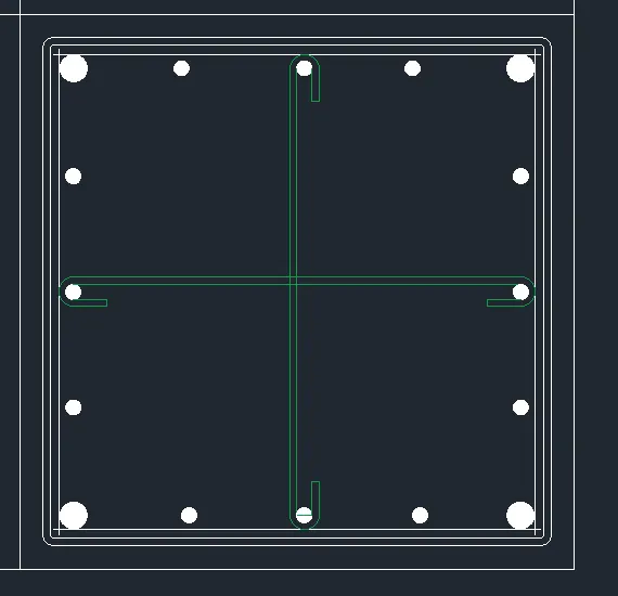
- Draw the hook.Make a 45 degree line and paste it at the circles quadrant.Trim thec ircles and join.Offset by 8 and move to the appropriate location
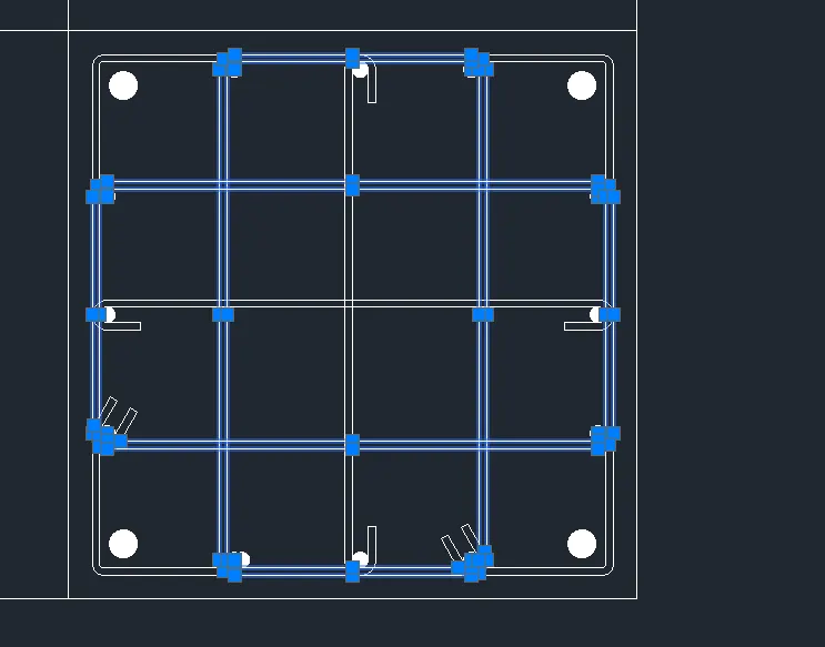
- create the remaining reactangle and add the text finish product
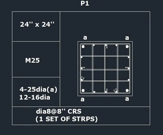
RESULT:
FINAL PRODUCT:
E.SKETCH 5-RAFT LAYOUT:
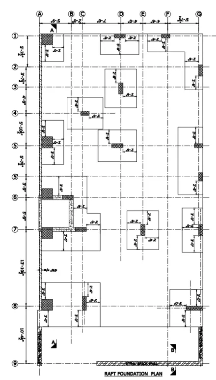
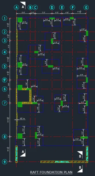
Challenge 5-Draw the Raft Layout as shown in the Figure. Assume the column size as per your knowledge. You can take the sizes as: 24”x24”, 9” x 24”, 9” x 18”, and 9’ x 24”. You can import the raft_foundation.pdf to ensure the missing dimensions.
PROCEDURE:
NOTE:Dimension used in this drawing is architectural
Layers used for this drawing are as follow
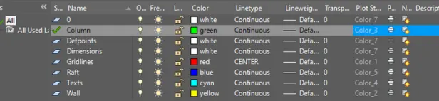
- Create the center line.Line style should be centerline
- Use dimlinesr and dimcotinue to add the dimensions
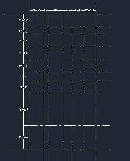
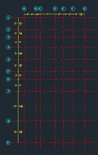
- Create teh tags circle and dtext command.Text height is 1' for bigger texts.Normal text height is 6"
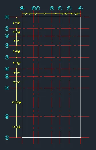
- Create the border lines.The raft itself
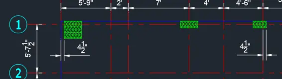
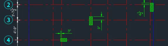
- Create the colums,Use rectangle tool.Position them accordingly
@grid 1
@grid 2-4
@grid5-5'
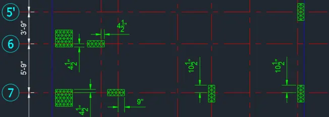
and so to upto grid 8
- Create the walls at grid 8-9 use rectangle tool, hatch and dtext to create the walls
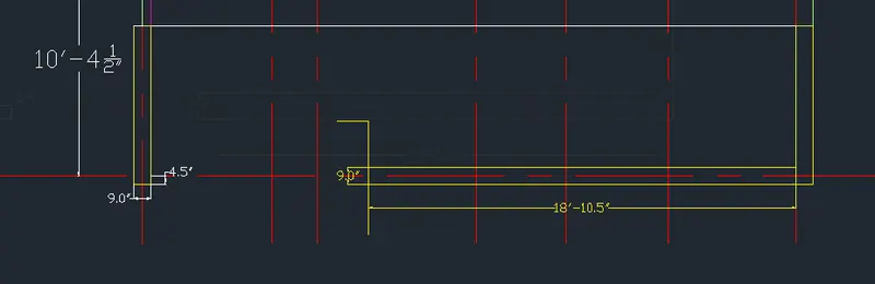
- Create the hatch for the wall using teh hatch tool.
- Add the text using dtext command
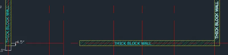
- Create the walls between grid 6&7 and hatch
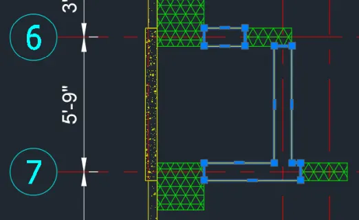
- Add the foundation outline including the dimensions,Use the line tool and rectangular tool
- Use dimlinear command to add the dimlinear
- Add outline for all foundation finish the product
RESULT:
FINISH PRODUCT:
3.CONCLUSION:
The AutoCAD software not only can provide drawings,but also reference through the use of other software such as PDF. By utilizing an image or a pdf file into the AUTOCAD software, one can assume or trace teh actual measurement of a given iamgeThe csaling system in AutoCAD also applies ro line scales and many more which controls the image shown in the interface