Creating a Wardrobe detailed drawing, Floor Plan, Kitchen Layout and Column Detail using AutoCad
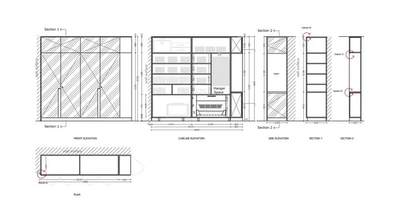
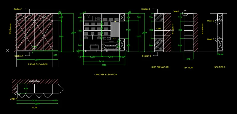
Aim - i) To draw the elevation and details of a wardrobe as shown in fig .
ii) To provide the dimensions and text with the use of layers .
Introduction - i) In give figure Elevation of wardrobe , Carcase elevation , Side elevation are given
ii) Along with that Sections drawings are also given in fig .
iii) Following Commands are going to used .
a) Line
b) Offset
c) Rectangle
d) Hatch
e) Dimlinear , Dimbase , Dimcontinue etc
f) Qleader
Procedure -
i) Open a new drawing (Cntrl + N) with imperical units
ii) Select units to Decimal and Precision (0.0) with Milimeters .
iii) Lim-max and limits are also set .
Step by Step Procedure
A) For Front Elevations -
Step 1)
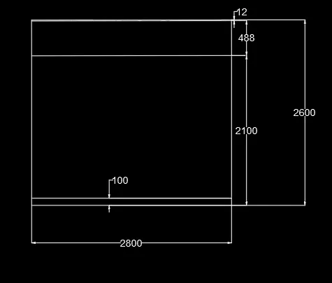
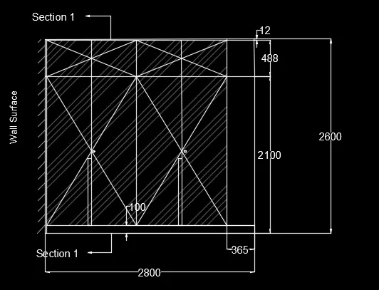
i) Command Rectangle
ii) Enter length = 2800 mm
iii) Enter width = 2600 mm
iv) Take offset of 12 mm and 480 mm from top
v) And from Bottom take 100 mm by giving command Offset .
vi) Measure the dimensions with default settings .
Step 2)
i) Draw the offset of 365 mm from right side to negative x direction .
ii) Then take midpoint of remaining area and draw a line using tool command.
iii) From top draw a diagonal from both sides of midpint lines .
iv) Draw a vertical line from intersection point of two diagonals .
v) Extend the line to top and bottom .
vi) Give command Hatch .
vii) Select hatch style - ANSl34 .
viii) Select hatch colour as grey
ix) Select scale factor = 500 .
x) Give command Qleader spcify 1st point and 2nd point and write text as Section 1 on top and bottom .
xi) Give the Annotations as shown in fig .
B) PLAN -
Step 1)
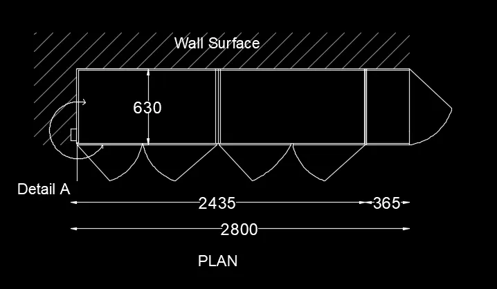
i) Take the outer projection of the above drawing and draw the plan drawing .
ii) Trim the unwanted lines .
iii) Draw a rectangular box to botttom right side bu command Rec
iv) Enter lengh =100 mm
v) Enter width = 50 mm
vi) Give the command Hatch to draw wall surface .
vii) Select Hatch Style - ANlS31 and Scale factor - 800
viii) Give hatch around the surface and hide the boundaries .
ix) Give the Annotations as shown in fig .
C) Carcase Elevations -
Step1)
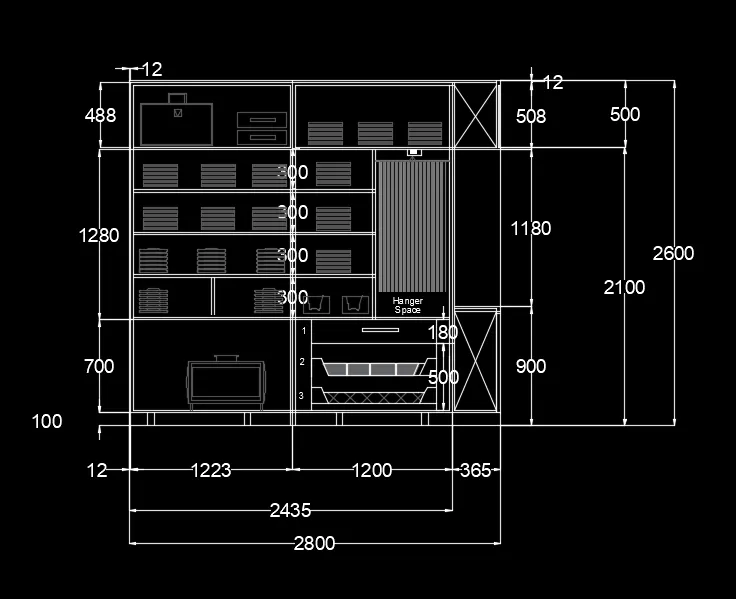
i) Take the Horizontal projection of Front elevations .
ii) Draw the rectangular box of 2800mm x 2600mm like front elevations . and draw External wall of 12 mm
iii) Take offset of 365 mm from right side .
iv) Take offfset of 700 mm from horizontal in positive y dirction .
v) Draw offset of 20 mm .
vi) Then take offset of 300 mm from previous lines in +ve y directions .
vii) Repat this 4 times as shown in fig .
viii) Take offset of 1235 mm from left vertically .
ix) Again take offfset of 1200mm from previous lines
x) Again take offset of 365 mm to complete the external geometry .
xi) Take inner offset of 20 mm as shown in fig .
xii) Draw the Wardrobe and Cabinets and assume the dimensions .
xiii) Create a New layer as Wardrobe and Cabinet - Change Colour as grey .
xiv) Apply this layrt to all furnitures .
xv) Give command Hatch .
xvi) Select Hatch - INSl37 and ANGLE respectively.
xvii) Apply as shown in fig .
xviii) Give Annotations - Font Style - Arial - Tex ht - 100 mm
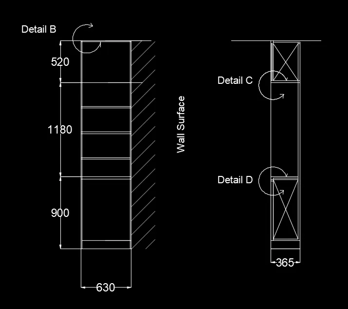
Step 3) Side Elevation , Section 1 , Section 2
1) For Side Elevations-
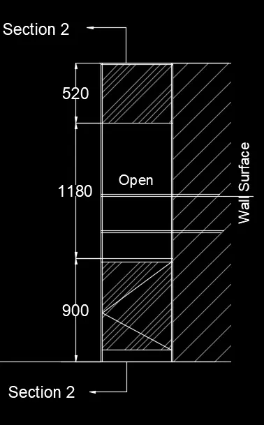
i) Take the horizontal projection from carcase plan .
ii) Copy the 1st block of 630mm x 2600mm from front elevation .
iii) Check the dimensions .
iv) Draw the Horizontal projection from Carcase plan to get the line of (900 mm , 1180 mm , 520mm)
V) Give command Hatch .
vi) Select Hatch - INSl34
vii) Apply as shown in fig at top and bottom .
viii) Give the Annotations with previous settings .
2) Section 1 and Section 2 -
Step 1)
i) Give the command Copy .
ii) Copy the Side elevation figure .
iii) Take the horizontal projection of 300 mm from Carcase plan .
iv) Draw the external geometry as shown in fig by taking projection from carcase plan .
v) Trim the unwanted lines .
vi) Follow the hatch command same as side elevations .
vii) Follow the Anntations command same as side elevations.
2) Section 2)
i) For Section 2 Give command Copy .
ii) Select the right side area of 365 mm x 2600 mm from carcase plan
iii) Copy that portion .
iv) Give command Mirror and select base point and mirror it ,
v) We will get same figure with same dimensions as shown in fig .
vi) Give the annotations as previously .
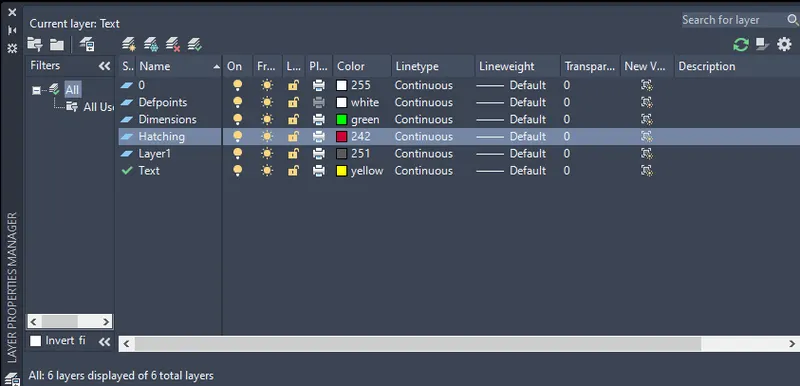
Step 4) Dimensions and text layers .
i) Command LA
ii) Create new layers
iii) Create Layer 1 - For Furnitures - select colour as grey .
iv) Label it as Dimensions and Text respectively .
v) Select Suitable colour .
vi) And Apply it .
Results - i) The elevation and details of a wardrobe as shown in fig . is drawn .
ii) And the dimensions and text with the use of layers is also shown .
2)
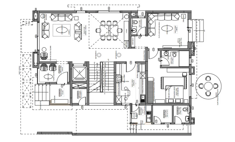
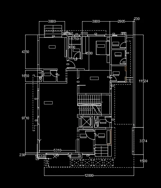
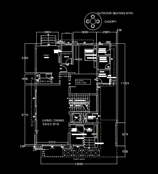
Aim - To draw a the floor plan as shown in the Figure.by using proper drafting tools to sketch the plan.
Introduction - i) Walls (Exterior and Interior)
Wall Thickness: Exterior Wall- 230mm, Interior Wall: 150 mm
ii) Doors and Windows: Assume the size of the doors and window.
iii) Stairs: Tread-300mm, Riser-150mm .
Commands used -
a) Line
b) Rectangle
c) Offset
d) Arc
e) Trim
f) Layers
g) Dimensions
h) DText
Assume Door Sizes -
| SR No | Door No | Door Size |
| 1 | D1 | 1100 x 2000 mm |
| 2 | D2 | 800 x 2100 mm |
| 3 | D3 | 900 x 2100 |
| 4 | D4 | 700 x 2100 |
| 5 | D5 | 750 x 2100 |
| 6 | SD | 2250x 2100 |
Assume Window Sizes and Ventilators
| SR No | Door No | Door Size |
| 1 | W1 | 2700 x 1500mm |
| 2 | W2 | 2500 x 1500 mm |
| 3 | W3 | 800 x1 500 mm |
| 4 | W5 | 1100 x 1500 mm |
| 5 | W9 | 750 x 1500 mm |
| 6 | W10 | 2200 x 1500 mm |
| 7 | V1 | 700x 500 mm |
| 8 | V2 | 800 x 500 mm |
Procedure -
i) Open a new drawing (Cntrl + N) with imperical units
ii) Select units to Decimal and Precision (0.0) with Milimeters .
iii) Lim-max and limits are also set .
Step by Step Procedure -
Step 1)
i) Command XL to draw a construction lines Horizontally and Vertically .
ii) Take a reference point at A .
iii) Start taking offset of external wall 230 mm from outer outer sides .
1) Living Room -
i) Take offset of 5310 vertically in +ve X direction
ii) And 9310 horizontally in +ve y direction .
iii) Give the openings for Window W1 , W2 , W5
2) Powder RM
i) Take offset of 1800 vertically in +ve X direction
ii) And 1650 horizontally in +ve y direction .
iii) Give the openings for Window V1 and D5
3) Family Rm
i) Take offset of 3880 vertically in +ve X direction
ii) And4350 horizontally in +ve y direction .
iii) Give the openings for Window D2 and SD3
4) Bedroom 1 and toilet
i) Take offset of 3830 vertically in +ve X direction from previous line
ii) And 4500 horizontally in +ve y direction from previous lines
iii) Give the openings for Window V1 , W1 , D2
5) Kitchen Room -
i) Take offset of 3210 vertically in -ve Y direction from Bedroom 1
ii) And 4300 horizontally in -ve y direction .
iii) Give the openings for Window D2 , D4
6) Staircase -
i) Tread-300mm,
ii) Riser-150mm
iii) Total 10 steps .
iv) Give the offset 300 mm and draw 10 steps .
7) Similarly we can draw other rooms also . Follow the previous steps and Create external geometry .
8) Draw a dotted line as shown in fig by taking offset of 50 mm from repective lines .
9) Front Lawn
i) Draw a front lawn by takin dimensions 11000 x 1200 mm and shown by dotted lines .
ii) Draw a internal blocks in front lawn by giving command REC
iii) Enter Length = 1000 mm
iv) Enter Width = 800 mm
v) Change the layer of rectangle to dotted lines
vi) Copy it to 4 times . as shown in fig .
Step 2) Annotations and Dimensions
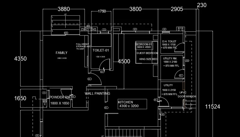
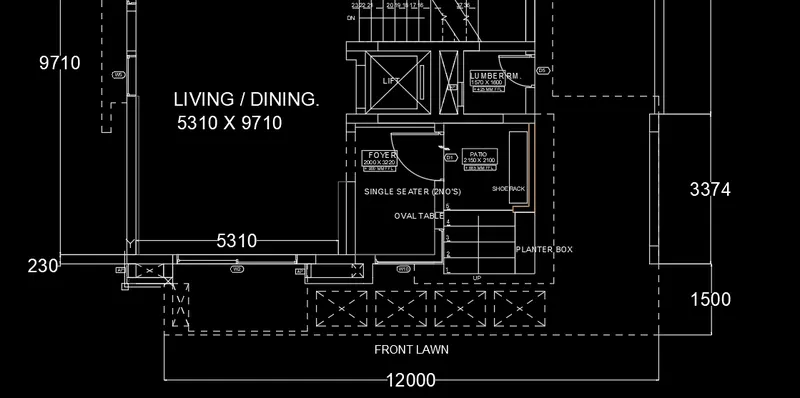
i) Give the Annotations as shown in fig
ii) Select text style - Arial -
iii) Text heihht - 100 mm
iv) Give the dimensions -
v) Select Standard form
vi) Dimension ht = 300 mm
Step 3) Canopy
1)
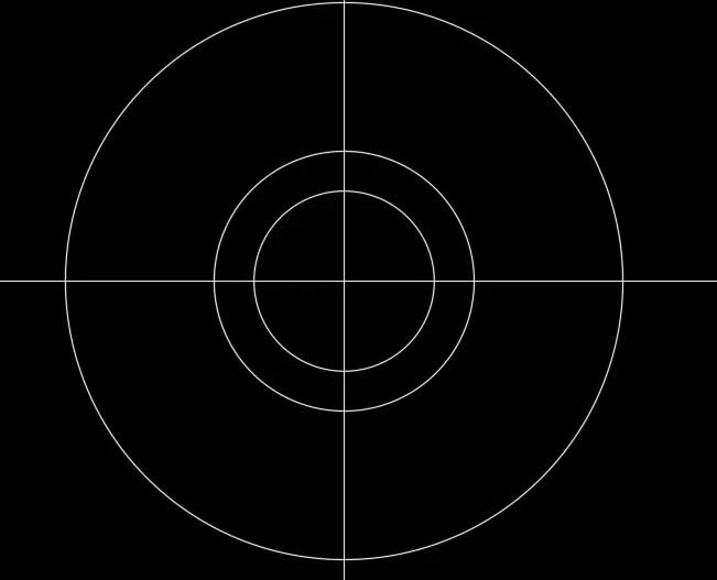
i) Command Circle (C)
ii) Select center point and draw a circle of radius 1398 mm
iii) Select same center point and draw a circle of radius 452 mm
iv) Draw the offset of 200 mm to this circle .
v) Command XL and draw horizontal and vertical construction lines to the circle .
2) Chairs .
i) Command Rectangle (Rec)
ii) Enter the length = 400 mm
iii) Enter width = 200 mm
iv) Command Arc and select start center end and draw the arc .
v) Take the offset of 25mm of the arc and draw one more arc .
vi) Again take offset of 100 mm from last arc to draw a new arc and join the corners of both arc by line
vii) To draw the handle of chairs give command Rec and give dimension (77mm x 107mm)

3)
i) Copy the chairs by giving command Copy (CO) .
ii) Command Miror and mirror it according to direction
iii) After mirroring give command Move and move it in such a way that its base should touches the offset of
200 mm circle .
iii) Repeat the same procedure to the other directions too .
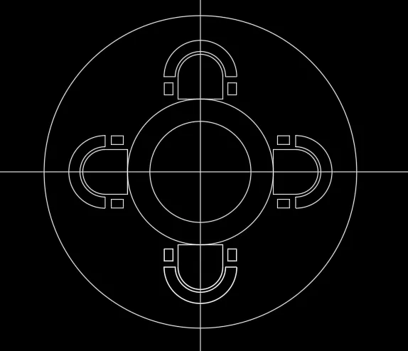
iv) After placing the chairs in all direction , Give command Fillet of radius 50mm to the base
of 400 mm x 200 mm of all rectangle .
iv) Trim the unwanted lines and give the dimensions .
v) Mentioned the assume dimesnsions .
vi) Give the command DIM - and measure the dimensions .
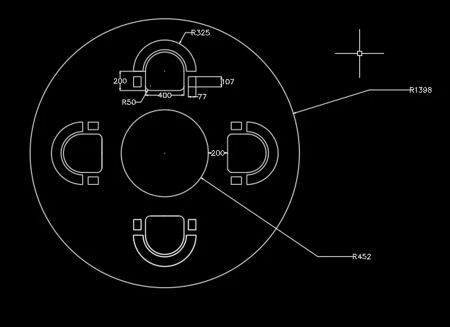
Results - The floor plan as shown in the Figure by using proper drafting tools to sketch the plan.
is drawn .
3)
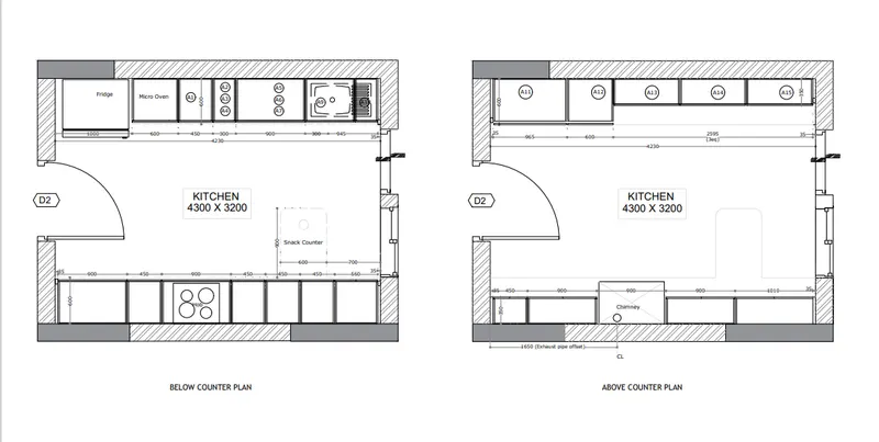
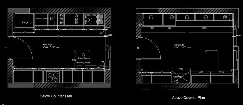
Aim - To create the Kitchen Layout as shown in the figure below.
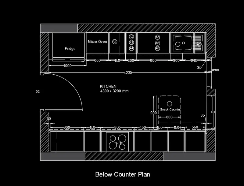
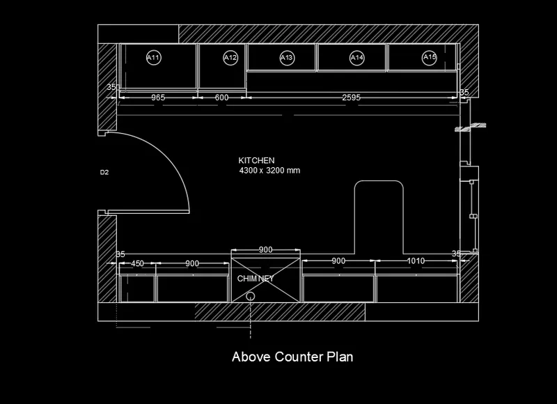
Introduction - i) In give fig there are two plans are given
a) Below counter plan
b) Above counter plan .
ii) Following commands are going to used -
a) Line
b) Rectangle
c) Offset
d) Trim
e) Arc
f) Dimension and Dtext .
Procedure -
i) Open a new drawing (Cntrl + N) with imperical units
ii) Select units to Decimal and Precision (0.0) with Milimeters .
iii) Lim-max and limits are also set .
Step by Step Procedure -
A) Below Counter Plan
Step 1)
i) Command Rectangle
ii) Enter the length = 4300 mm
iii) Enter the width = 3200 mm
iv) Take the offset of 35 mm to the inner side .
v) Draw the external wall as thickness 230 mm .
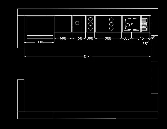
v) To draw the Fridge -
i) Enter length =1000 mm
ii) Enter width =800 mm
vi) For Micro oven -
i) Enter length =600 mm
ii) Enter width =600 mm
vii) For Section A1
i) Enter length =450 mm
ii) Enter width =600 mm
viii) For Section A2 A3 A4
i) Enter length =300 mm
ii) Enter width =600 mm
ix) For section A5 A6 A7
i) Enter length =900 mm
ii) Enter width =600 mm
iii) Remaining portion is for sink .
iv) Draw the sink as shown in fig .
Step 2)
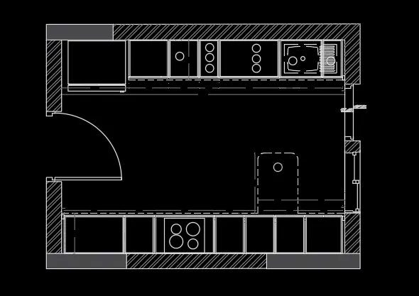
i) Give command Rec . at the bottom side
ii) Enter length = 4230 mm
iii) Enter width = 600 mm
iv) Take the offset of 35 mm in +ve X direction . and Repeat the command for for following offsets
v) Such as 900 mm , 450 mm , 900mm , 450 mm , 450 mm , 450mm , 560mm , 35 mm .
vi) Take the offset of 700 mm and draw the Snack Counter and change the layer to dotted line .
vii) Enter the length as = 600 mm
viii) Enter the width as = 900 mm
ix) Use Command Fillet and apply it the corner of top side
x) And Carry forward this horizontal to left side and join to the external wall .
xi) Command LA and Select dotted line and apply on snack counter .
xii) Draw the HOB as shown in fig .
xiii) Command Circle and give radius as 60mm and 80mm respectively.
xiv) Draw the Door D2 - Assume Dimension as (800mm x 2100mm)
xvi) Command Hatch - Select style - ANSl32 and apply it on external wall .
xvii) Repeat the command - Select stye - Soild fill - Select colour - Grey and apply it as shown in fig .
Step 3) Give the dimensions and Annotations -
i) Command D and modify the dimensions
ii) Select text height as 75 mm
iii) Arrow size = 50 mm.
iv) Command DIMCONTINUE to get the dimensions
v) Command Dtext and select Arial font and text height 60 mm
vi) Give Annotations .
B) Above Counter Plan -
Step 1)
i) Copy the Below counter plan
ii) Trim the unwanted lines .
iii) Follow the same procedure for Above counter plan also .
Results - The Kitchen Layout as shown in the figure is drawn .
4)
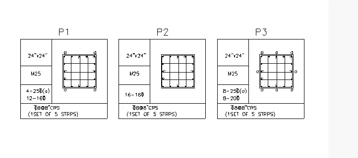
Aim - To sketch Column reinforcement details as shown in figure .
Introduction - i) Column details reinforcement are given in figure .
ii) 8mm ---- 0.31 Inches
ii) 25mm--- 1 inches
iii) 16mm—0.62 inches
Procedure -
i) Open a new drawing (Cntrl + N) with imperical units
ii) Select units to Decimal and Precision (0.0) with Milimeters .
iii) Lim-max and limits are also set .
Step by Step Procedure -
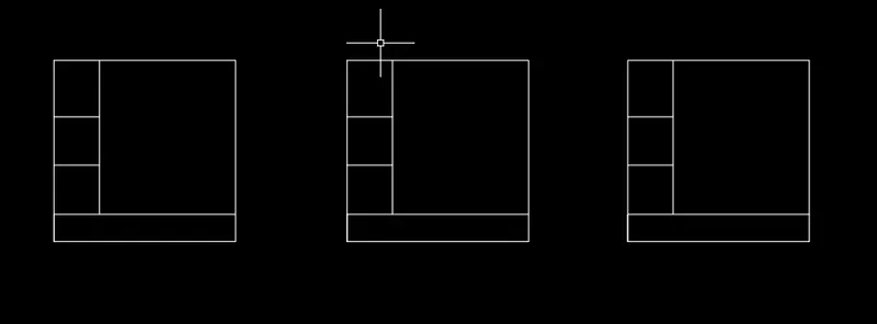
Step 1)
i) Give Command Rec
ii) Enter the length = 1000 mm
iii) Enter width = 1000 mm
iv) Take the offset of 250 mm horizontal
v) Take the offset of 150 mm vertical .
vi) Make the boxes as shown in fig .
vii) Command Copy and copy it horizontally at 3 times (P1 , P2 , P3)
Step 2) Draw the reinforcement
i) Command Line tool and draw the main and distribution steel as shown in fig .
ii) Give command Circle and shows the diameter of bars .
iii) Give the Annotations as shown in fig
iv) Selelct style - Arial - Text ht = 45 mm
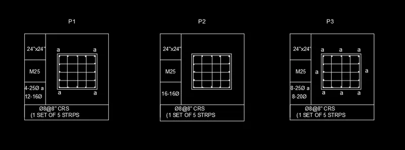
Results - Column reinforcement details is drawn .
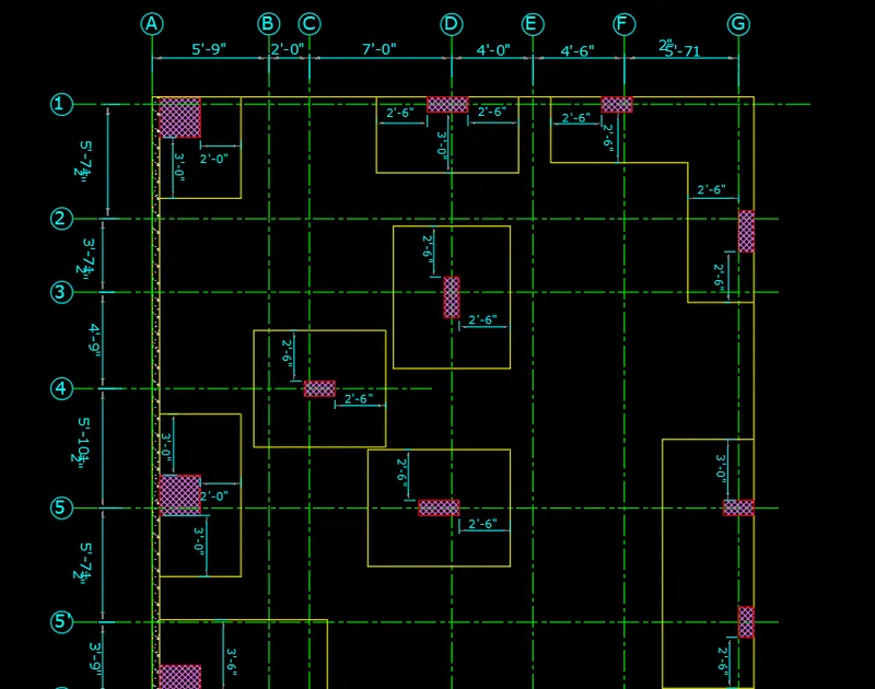
5)
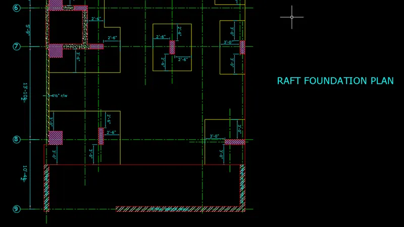
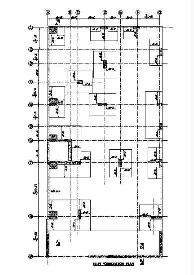
Aim - To draw a raft layout as shown in fig by assuming the column sizes .
Introduction - i) Details of raft foundation is given
ii) Assume the column sizes ( 24”x24”, 9” x 24”, 9” x 18”, and 9’ x 24”)
iii) Following commands are used -
a) Line
b) Rectangle
c) Offset
d) Trim
e) LA
f) Dimension and Dtext .
Procedure -
i) Open a new drawing (Cntrl + N) with imperical units
ii) Select units to Architectural and Precision (0'.01/2") with feet and inches
iii) Lim-max and limits are also set .
Step by Step procedure
Step 1)
i) Give command Rec .
ii) Enter length = 29'-7"
iii) Enter width = 60'
iv) Draw the rectangle .
v) Command offset and take the offset as shown in fig with given dimensions .
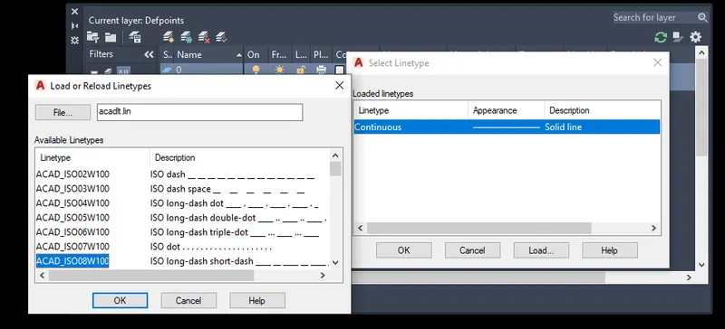
vi) The offset line is shown by dotted lines
(Command LA - Select line type - Load - ISO Long dash Short dash)
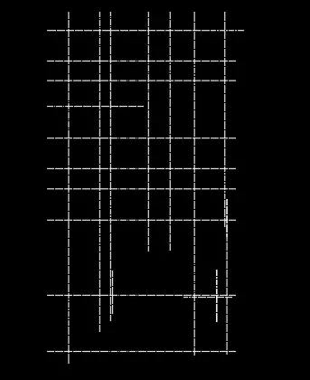
vii) Now draw the grid of raft foundation by taking offsets .
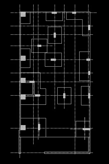
Step 2)
i) Give command Rec
ii) Enter length = 2'
iii) Enter width = 2'
iv) Draw the columns as shown in fig with given locations .
v) Along with that draw the footing around th column by giving command Rec .
vi) Command Hatch - Select type - ANS lS137 and hatch the column
vi) Command Hatch - Select type - ANSl133 to hatch the walls .
Step 3)
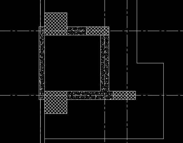
i) At grid 6 - 7 there is PCC .
ii) To show that take a offset of 4" to the outer sides .
iii) Command Hatch - Select type - AR Concrete .
iv) And apply it
Step 4)
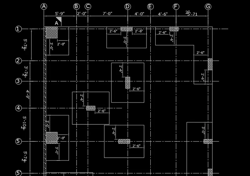
i) Give the naming to grid pattern as 1 - 2 - 3 -----9 in Y axis
ii) Give the naming to grid pattern as A - B- C -----G in X axis
iii) Give the Annotations and Dimensions as shown in fig
iv) Give command Dimcontinue to get the dimensions
v) Select the Dimension height as 2.5 '
vi) For Annotations
a) Select style - Arial - text height - 5'
b) Give the annotations as shwon in fig .
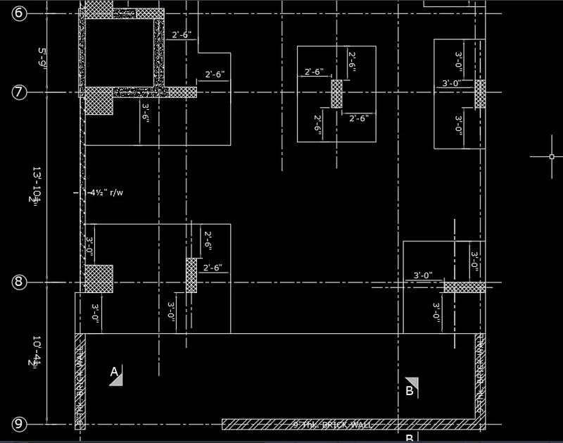
Apply the layer colour to the different different layers which are created .
Results - The Given Raft Layout is drawn as per given figure .