Creating a Wardrobe detailed drawing, Floor Plan, Kitchen Layout and Column Detail using AutoCad
1. AIM
To draw the elevation and details of wardrobe using AutoCAD 2022
INTRODUCTION
- A wardrobe is a standing closet used for storing clothes.
- The earliest wardrobe was a chest, and it was not until some degree of luxury was attained in regal palaces and the castles of powerful nobles that separate accommodation was provided for the apparel of the great.
- The name of wardrobe was then given to a room in which the wall-space was filled with closets and lockers, the drawer being a comparatively modem invention
PROCEDURE
STEP-1
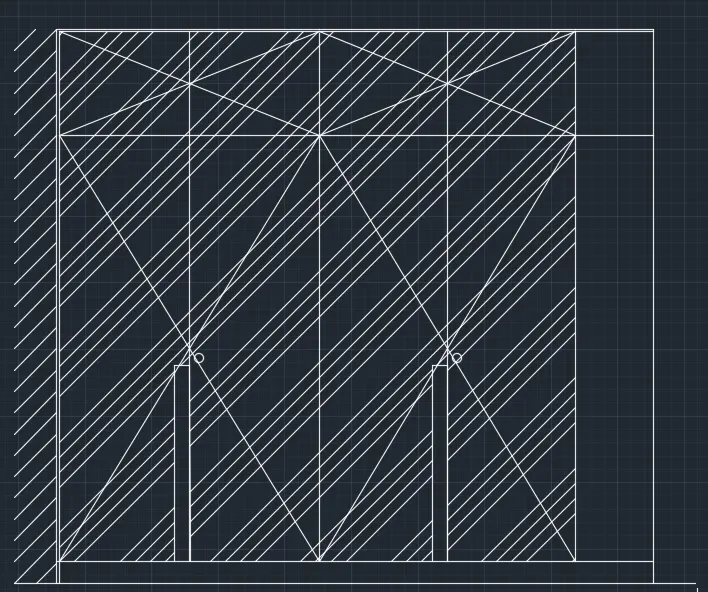
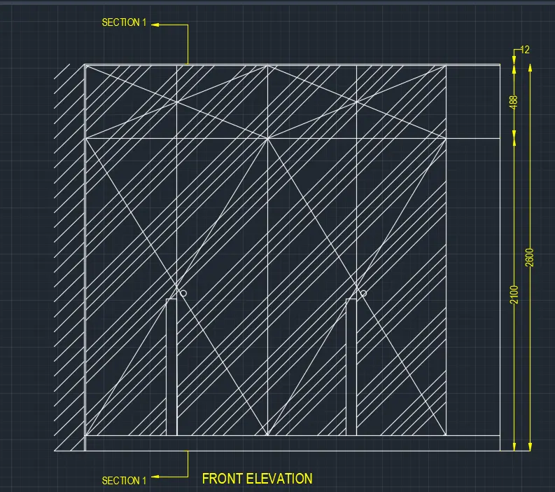
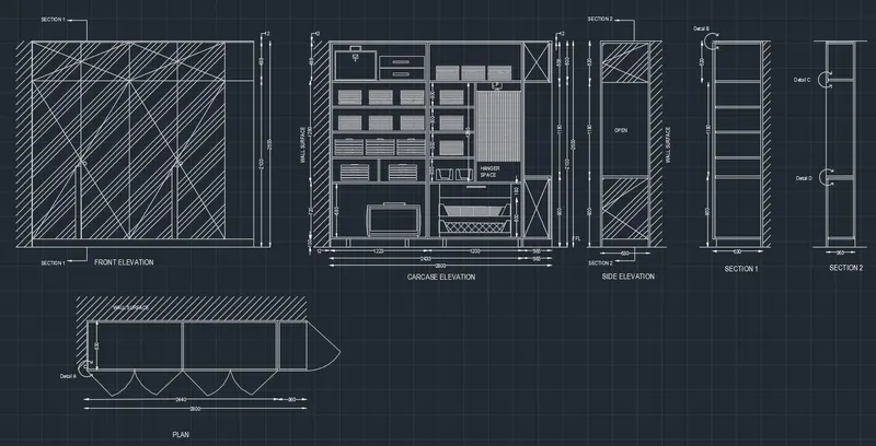
FRONT ELEVATION
- First, draw the line with line command of length 2800mm and draw a line.
- Next divide the vertically 5 times.
- take the offset command and offset the horizontal line from the top with the length of 500mm
- Again, offset line to 12mm, and again offset the line from bottom of length 20mm.
- draw the line crossly from 1 vertical line top to the third line bottom.
- Do this step continuously when the figure completes the drawing Next, we have to hatch and put the dimensions for every part in the figure. And we have to enter the text for required part in the figure.
STEP-2
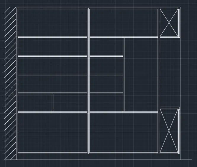
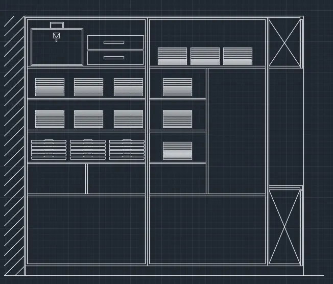
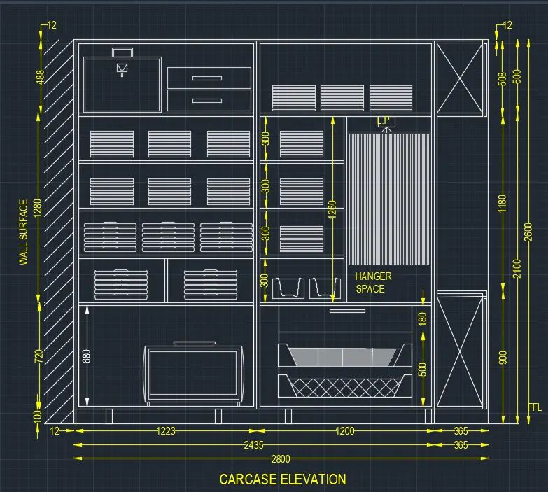
CARCASE ELEVATION
- First, draw the line with line command of length 2800mm and draw a line again upwards with the length of 2600mm. And next we have to draw the line backwards from the right corner of top with the length of 2800mm.
- Then next join first line and the last line
- Next, divide the selves in the wardrobe into 6 parts vertically, and divide three parts horizontally.
- Hatch the all parts in the carcase elevation
- use the trim command to trim the unwanted lines and objects
- the different selves are created as shown in the figure below.
- Using the line command and offset command we draw the different parts in the wardrobe as shown in the figure below.
- Finally, we put the dimensions for every part in the diagram as we drawn below.
STEP-3
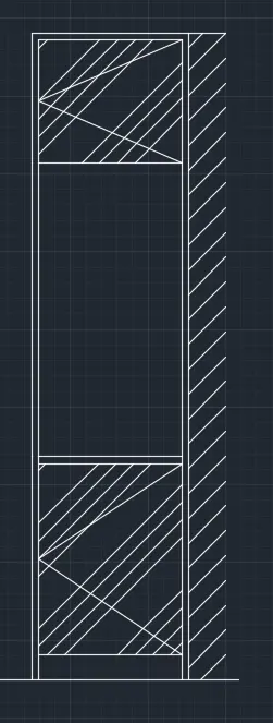
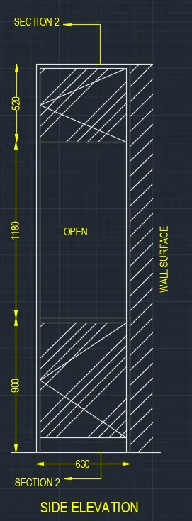
SIDE ELEVATION
- The side elevation in detail.
- Draw the line using line command with the length of 630mm horizontally forwards. And again, draw the line vertically upwards with the length of 2600mm from the previous line drawn,
- Draw the horizontal line backwards from the top with the length of 630mm
- And join the first line and the last line which have drawn previously.
- After the offset the bottom line with the length of 20mm. Similarly make the offset to all the side in the figure.
- Next use the hatch command to hatch, and put the dimensions where requires. And we have to put the dimensions for every part in the figure
STEP-4
SECTION-1
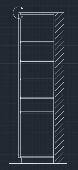
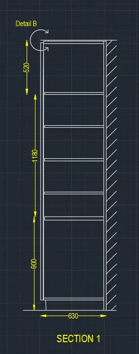
- Next, draw the section-1 in detail
- First, draw the line using line command with the length of 630mm horizontally forwards
- And again, draw the line vertically upwards with the length of 2600mm from the previous line drawn
- Next again draw the horizontal line backwards from the top with the length of 630mm
- And join the first line and the last line which have drawn previously. Next divide the six parts from bottom to top with different dimensions drawn.
- After the offset the bottom line with the length of 20mm, similarly make the offset to all the sides in the figure.
- Next use the hatch command to hatch, and put the dimensions where requires
- put the dimensions for every part in the figure.
- And we draw the detail B at the top of the left comer shown in figure
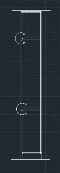
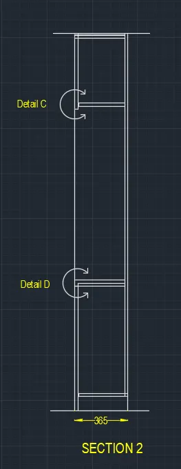
- Next divide the three parts from bottom to top with different dimensions. After the offset the bottom line with the length of 20mm
- Similarly make the offset to all the sides in the figure. And we have to put the dimensions for every part in the figure
- And draw the detail-Carid detail-D at middle part of the both left comers shown in figure.Now we draw the cross lines in the first part and third part of the figure.
STEP-5
PLAN
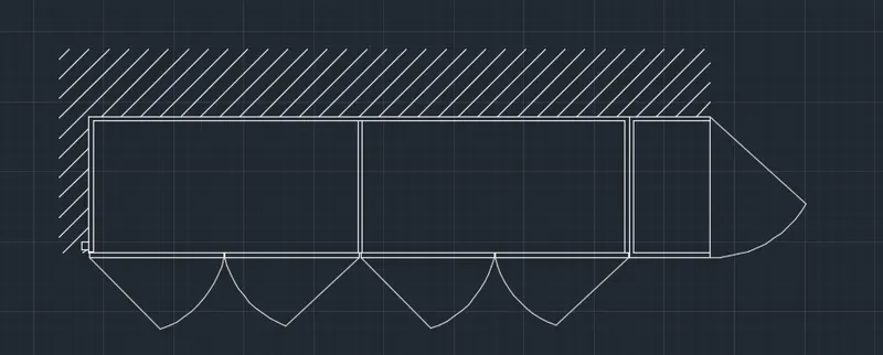
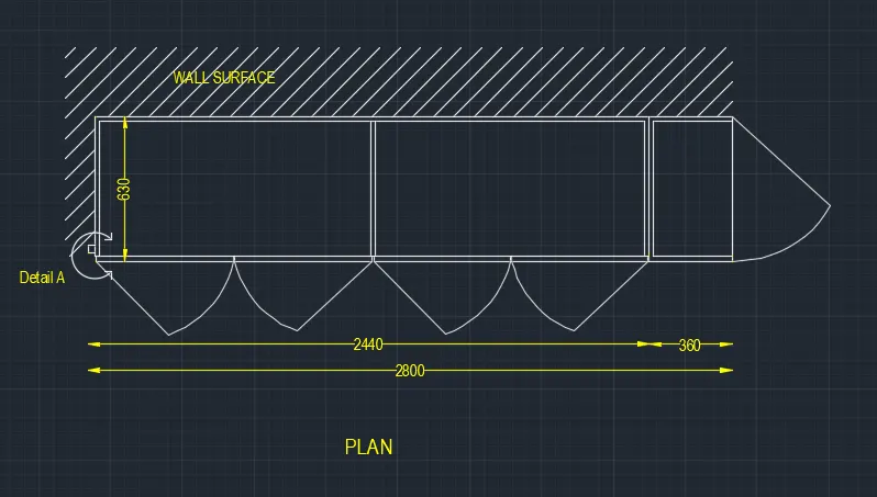
- First, draw the length of 2800mm. And next we have to draw the length of 630mm upwards vertically.
- Then again draw the length of 2800mm backward horizontally. Next join the first line and the last line which we drawn previously.
- Next use the offset command to offset the all sides of the figure to inside, and the offset of length 20mm
- Next use the hatch command to hatch the outer side of a figure, that outer side is a wall surface,
- And we draw the Detail-A at the left side comer of the figure at the bottom as shown in figure.
- Finally, we have to put the dimensions for every part in the figure.
RESULT
The elevation, plan and details are created successfully using AutoCAD
2. AIM
To draw the given floor plan in the AutoCAD 2022 in detail
INTRODUCTION
- A floor plan is an architectural drawing showing the spatial layout of a building
- It is generated by having an imaginary horizontal line/plan that is cutting the building at 3-4 from the base
- The result is a diagrammatic drawing showing a wide range of information from rooms structure layouts, materials, dimensions
- A Presentation floor plan is a floor plan but without the technical information such as dimensions, annotations, and technical details
PROCEDURE
STEP-1
- First, draw the line downwards vertically with the length of 17348.00
- Next, draw the line horizontally with given length,
- Next again draw the line downwards vertically with the length of 17348.00
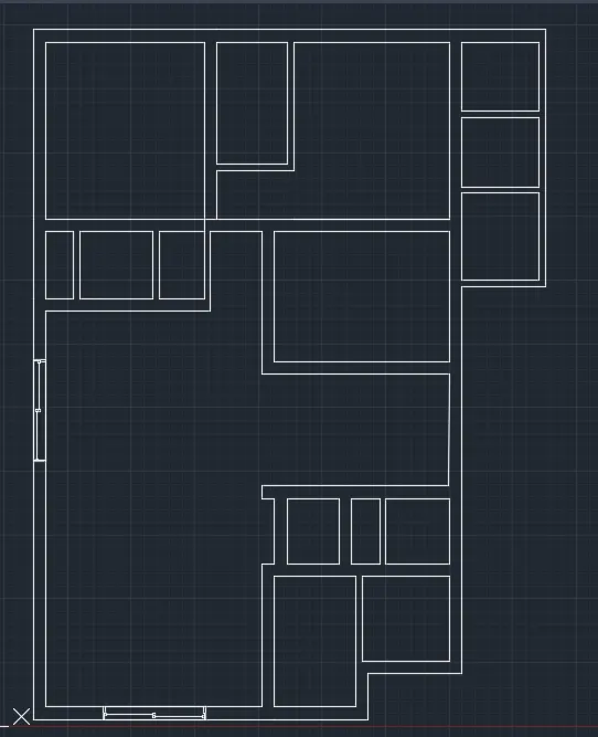
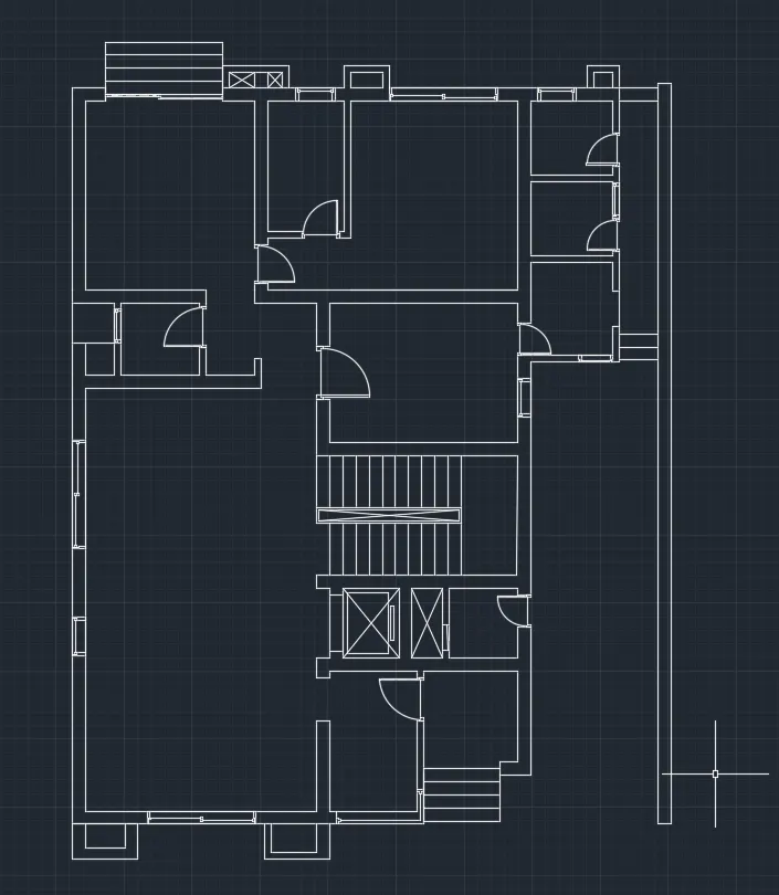
- First, we have to draw a family room
- Next draw the family room of length 3880 and width of 4350mm
- And also draw the toilet room of length 1750mm and width of 3000mm
- Again, draw the line using the line command with the length of 1800mm and width of 1650mm.
STEP-2
- Next, draw the D.H. Toilet rooms with the length of 1900mm and width of 1700mm.
- And next draw the utility room with the length of 1900mm and width of 2100mm.And again draw another utility room with the length of 1900mm and width of 2150mm.
STEP-3
- Next draw the family room of length 3880 and width of 4350mm
- And also draw the toilet room of length 1750mm and width of 3000mm
- Again, draw the line using the line command with the length of 1800mm and width of 1650mm
STEP-4
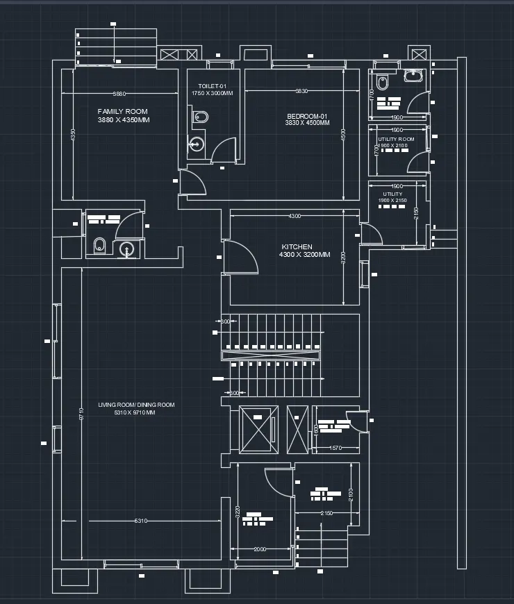
- Now we draw the kitchen room with the length of 4300mm and width of 3200mm.
- draw the foyer with the length of 2000mm and width of 3220mm,
- draw the Patio with the length of 2150mm and width of 2100mm.
STEP-5
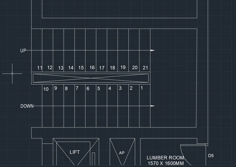
- And next draw the lumber room with the length of 1570mm and width of 1600mm. And next we draw the Lift with the length of 1570mm and width of 1600mm
- Next, draw the stairs of thread 300mm and riser 150mm.
- And the number of steps from top to bottom is 12 numbers of both sides’ upside and downside.
STEP-6
- Now draw the kitchen room with the length of 4300mm and width of 3200mm.
- Next draw the foyer with the length of 2000mm and width of 3220mm.
- Next draw the Patio with the length of 2150mm and width of 2100mm.
STEP-7
- Now draw the compound wall with the wall thickness of 230mm and length of 17328mm.
- again draw the mini stairs attached to compound wall with 300mm treads and 150mm riser.
- Next trim the unwanted lines and objects in the floor plan using the trim command
STEP-8
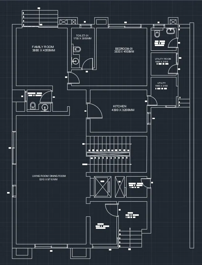
- Next put the dimensions wherever required in in the drawing and we need to indicate the rooms and objects with the single text command. And we create the doors, windows and ventilator with dimensions as written below
DOORS
D1 = 900 x 1900mm
D2 = 800 x 2000mm
D3 = 300 x 2000mm
D4 = 750 x 2100mm
D5 = 700 x 2100mm
SD = 2256 x 2100rm
WINDOWS
W1 = 2700 x 1500mm
W2 = 2500 x 1500mm
W3 = 900 x 1500mm
W4 = 1000 x 1500mm
W5 = 800 x 1500mm
VENTILATORS
V1 = 800 x 500mm
V2 = 750 x 500mm
RESULT
The given plan is created successfully using AutoCAD
3. AIM
To draw the kitchen layout with proper dimension techniques in the AutoCAD 2022 in detail,
INTRODUCTION
- kitchen layout is the most important part of designing your perfect kitchen
- It's the layout that will determine how you cook, how you eat and how you socialise
- So, whether you're totally remodelling the kitchen, buying new appliances or simply replacing the cabinets, we've included the top five most common kitchen layouts to help inspire you
PROCEDURE
STEP-1
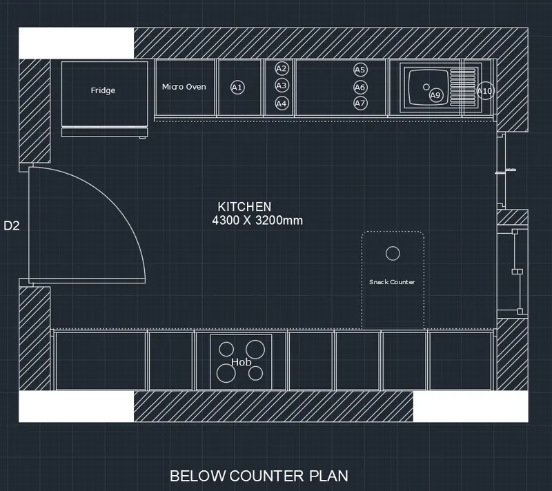
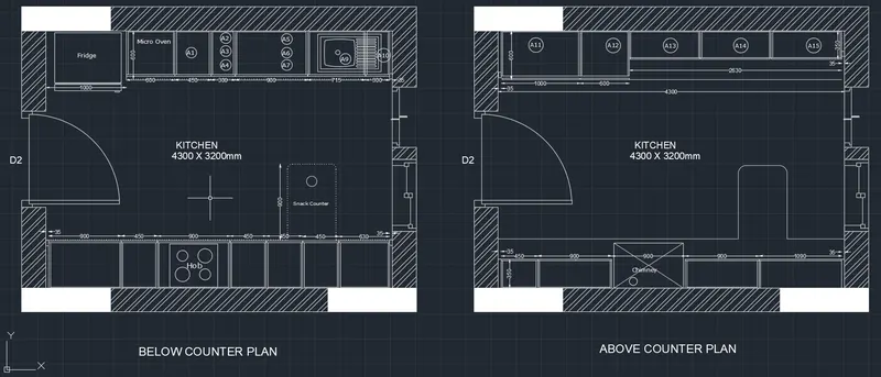
- Below counter plan, first we have to draw the line horizontally with the length of 4300mm
- Next draw another line from the previous line with the length of 3200mm vertically upwards
- Next again we draw the line from previous line with the length of 4300 mm horizontally backwards at the top.
- Next, join the first line and the last line which we have drawn previously
- Next, offset the line inside with the offset command with the length of 600mm including the fridge
- Next offset the four sides with the offset of 20mm outside,
- Afterwards we draw the fridge separately with other dimensions in the kitchen layout
- Next, draw the line opposite side to create the parts of kitchen
- Next divide the seven parts downsides with different dimensions compared to the upper side single text portion
- Next leave the space left and right comers with the length of 35mm at the top and bottom
- Next, we have used the single text command and indicate the parts where ever it requires with
- And put the dimensions for every part in the diagram. - Next draw the snack counter with the length of 600mm and width of 900mm, and draw the circles to create the hub in the middle at the bottom of the kitchen
- And create the windows using the line command and trim command, which is shown in the below figure
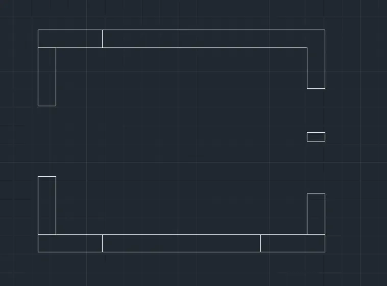
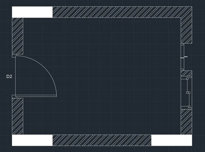
STEP-2
- Above counter plan, first draw the line horizontally with the length of 4300mm
- Draw another line from the previous line with the length of 3200mm vertically upwards Next again draw the line from previous line with the length of 4300 mm horizontally backwards at the India top
- Join the first line and the last line which we have drawn previously. Next offset the four sides with the offset of 20mm outside
- Offset the line inside with the offset command with the length of 350mm, and again we do offset of 600mm in the same side.
- And leave the space for both side comers with the length of 35mm, And do offset for the inside parts with the length of 10mm for all sides of the all parts in the kitchen layout, Next do the offset of 350mm at the bottom portion of the kitchen, And the bottom portion into five parts, and again offer them with the length of 10mm
- Use the different hatch styles to hatch the walls in the kitchen layout. Next draw the doors using the line command, circle command and trim command
- Draw the windows using the line command and trim command
- use the dim linear command to put the dimensions where ever they are required, use the single text command to indicate the kitchen parts in the kitchen layout which we have drawn in the below figure
- Finally, draw the snack counter with the length of 600mm and width of 900mm,
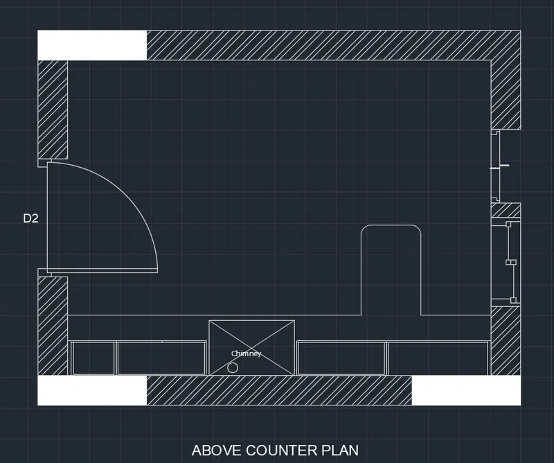
RESULT
The kitchen is drawn successfully in AutoCAD
4. AIM
To draw the column details with proper dimensions in the AutoCAD in detail
INTRODUCTION
- Columns are the vertical members of a building structure that use to support the slabs and beams.
- It serves as a backbone of the structures so we can achieve the height that we wanted in a given project.
- A column comes with different types that vary in shapes and sizes depending on the loads and conditions of a structure.
- Design of columns had a different approach according to each type, whether it is a plain concrete column, a reinforced concrete column a steel column and a composite one.
- Although the design differs accordingly, columns are classified and designed according to its length the short and the long column.
PROCEDURE
STEP-1
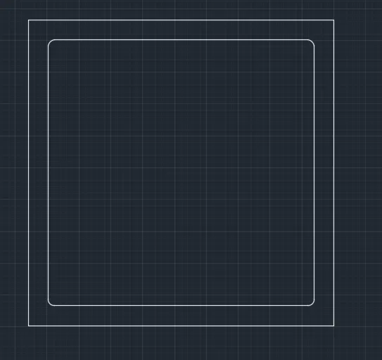
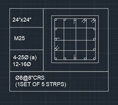
- First the column with given details as shown in below figure next draw the line with the length of 24” horizontally.
- Next, draw the 24" line vertically, then again draw the line with the length of 24”
- Finally join the first line and last line. Then after create offset of 0.6, and do the offset to inside of rectangle we drawn previously.
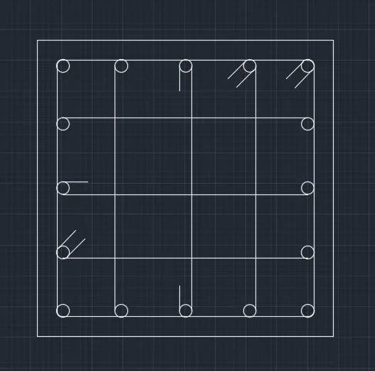
- Now take the circle diameter as 16mm and 20mm separately. Now use the divide command and give the 4 segments inside the rectangle
- Now place the circle in every segment.
- After putting the 20mm diameter circles at the 4 comers in the column.
- Mirror the one side fixed circles to other side. Next place the 16mm rods in the remaining places. And put the 5 stirrups in the column where they are required to put in certain position. And bend the corner of stirrups to the 45 degrees, as shown in below
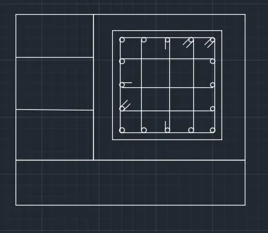
- Finally, draw the table using the line command as shown in below table
- Next, enter the details of columns with Single text. And next place the column diagram in the table we created, as shown below.
STEP-2
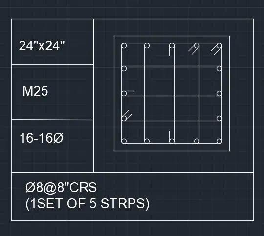
- draw the column with given details as shown in below figure.
- First draw the line with the length of 24 horizontally.
- draw the 24" line vertically, then again Finally we join the first line and last line draw the line with the length of 24"
- Then after do offset of 0.6", and do the offset to inside of rectangle we drawn previously.
- Next draw a circle beside of the previous figure, we take the circle diameter as 16mm
- Now use the divide command and give the 4 segments inside the column.
- Now place the circle in every segment.
- After putting the circles on one side, we use the Mirror the one side fixed circles to other side
- And put the 5 stirrups in the column where they are required to put in certain position. And Bend the comer of stirrups to the 45 degrees, as shown in below figure
- Finally, we have to draw the table using the line command as shown in below table.
- need to enter the details of columns with Single text.
- And next place the column diagram in the table we created, as shown below.
STEP-3
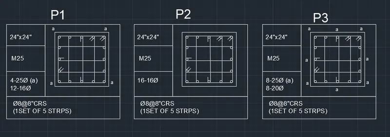
- draw the column with given details as shown in below figure.
- First draw the line with the length of 24” horizontally.
- Next draw the 24" line vertically, then again draw the line with the length of 24"
- Finally, join the first line and last line.
- Then after do offset of 0,6”, and do the offset to inside of rectangle we drawn previously.
- Now take the circle diameter as 25mm and 20mm separately. Now use the divide command and give the 4 segments inside the column.
- Now place the circle in every segment. After putting the 20mm dia circles at the 4 comers in the column. And we need to put the 25mm bars in the middle of the four sides in the column.
- Next place the 20mm rods in the remaining places.
- And put the 5 stirrups in the column where they are required to put in certain position And bend the comer of stirrups to the 45 degrees, as shown in below figure.
- Finally, have to draw the table using the line command as shown in below table
- Next need to enter the details of columns with Single text.
- And next place the column diagram in the table we created, as shown below.
RESULT
5.AIM
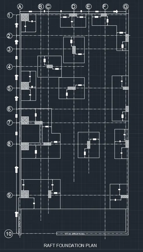
To draw the raft foundation layout in the AutoCAD 2022 with proper dimensions in detail
INTRODUCTION
- Raft foundation is actually a thick concrete slab resting on a large area of soil reinforced with steel supporting columns or walls and transfer loads from the structure to the soil.
- Usually, mat foundation is spread over the entire area of the structure it is supporting
- Raft foundation is generally used to support structures like residential or commercial buildings where soil condition is poor, storage tanks, silos, foundations for heavy industrial equipment.
PROCEDURE
STEP-1
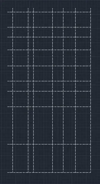
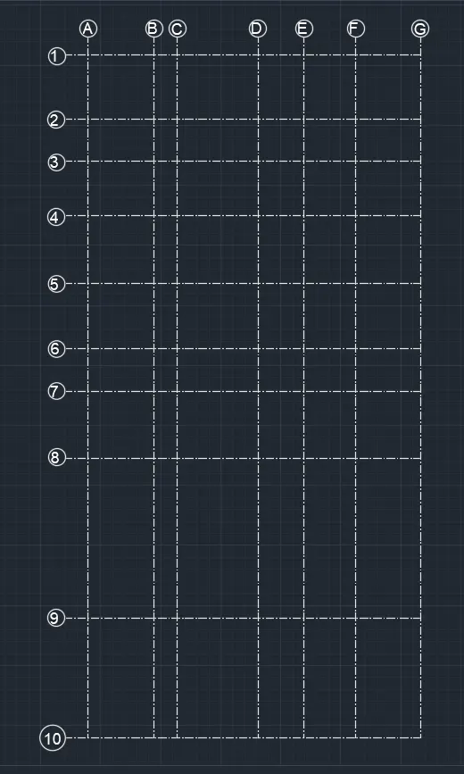
- First have to open the AutoCAD and set the limits using the limits command. Next select the Xline command and set to horizontal and vertical.
- And make that Xlines as the grid lines for the drawing of the raft layout.
- Offset the vertical lines up to seven lines.
- offset the horizontal lines up to nine lines
- name the horizontal lines with numbers. And name the vertical grid lines with the alphabets.
- And also draw the walls where they are required in the drawing, using the line command and offset command
STEP-2
- Next draw the column and footing with the required dimensions
- take the column length is 24" and the width is 24"
- And the footing length is 2’-24" and width is 3’-24"
STEP-3
- Next draw the column and footing with the required dimensions.
- take the column length is 9" and the width is 24" And the footing length is 5’-24" and width is 3’-24”
STEP-4
- Next draw the column and footing with the required dimensions.
- take the column length is 9" and the width is 24”
- take the column length is 9" and the width is 18"
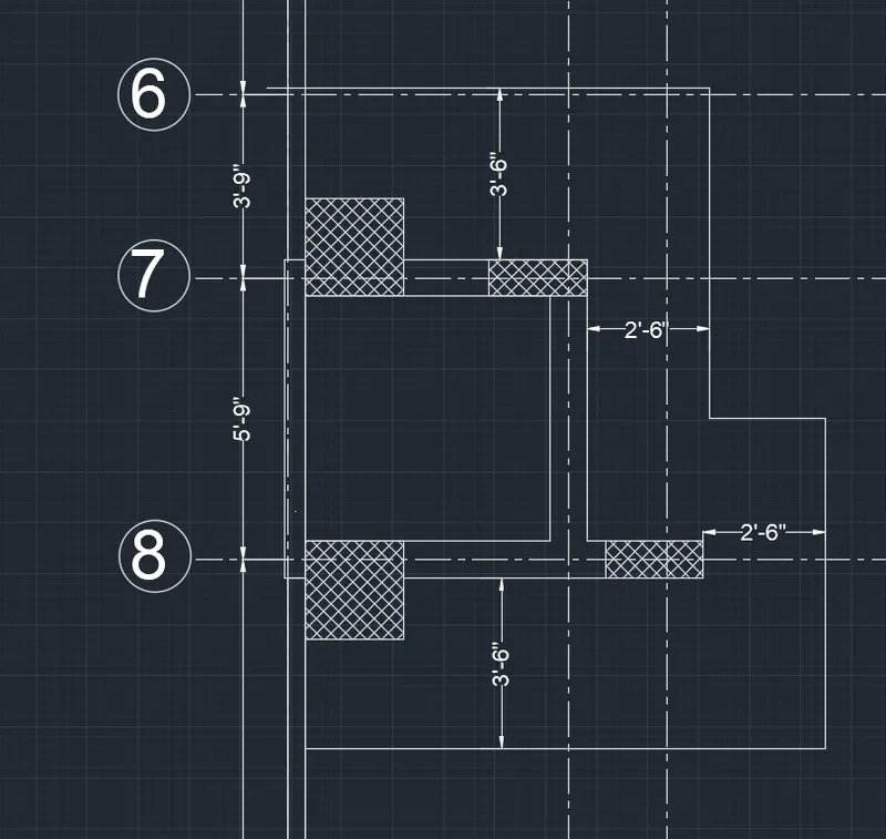
- Next do the offset of 2’-6” horizontally and vertically from the columns.
- Next join the comers with the fillet command taking the radius as zero. Now use the hatch command to fill the columns.
STEP-5
- Next draw the column and footing with the required dimensions.
- take the two columns length is 9" and the width is 24". take the one column length is 9" and the width is 18"
- Next offset of 2’-6” horizontally and vertically from the columns
STEP-6
- Next draw the column and footing with the required dimensions
- take the column length is 24" and the width is 24” Next do the offset of 2'-6" horizontally and vertically from the columns.
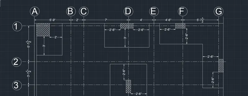
STEP-7
- Now take the two columns with the length of 24" and width of 24. And again, need to provide another two columns with the size of 9" x 24"
- And put the columns in the required position and draw the footing with reference to the column placement with the standard dimensions as shown in the figure,
STEP-8
- Next need to provide column size as 9" x 24"
- Here we take the two columns that the column size are mentioned above And again we draw the footing with reference to column.
- Here there is two columns, one column is placed horizontal and one column is placed vertically
- The sizes from first column we take the offset of 3’ and another column with the 2’-6" length we take the offset
- By using this dimension
STEP-9
- Here have the two columns with two footings
- draw them separately. The first footing is drawn with the reference of the column size. Next offset of 2'-6" horizontally and vertically from the first column.
- Next we do the offset of 3'-0" horizontally and vertically from the second column. draw the footing
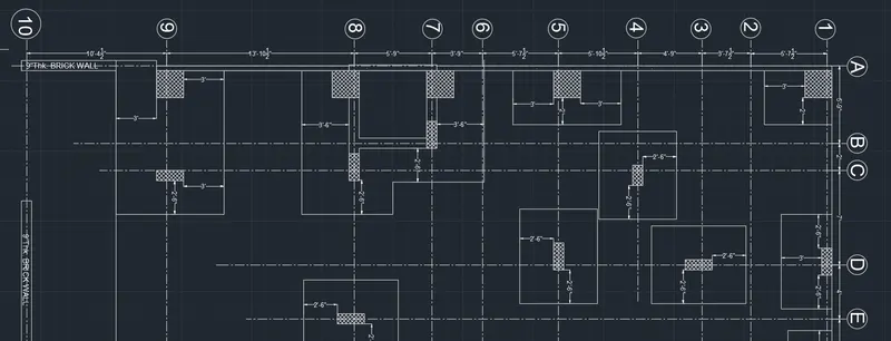
STEP-10
- Similarly, from the above footings and columns, draw the footings with the reference of the size of the columns.
- Here there is two columns in the first footing, the first column size is 24" x 24" And next column size is 9 x 24". By using this column sizes, draw the footings
- draw the another footing beside of it. In the other footing the column size is 9" x 24"
- Next do the offset of 3'-0" horizontally and vertically from the columns
- With reference to the column size, another footing is also drawn.
RESULT
The raft foundation was drawn with the proper dimension techniques in the AutoCAD in detail