Creating a Residence Layout, Seating plan, Toilet and Utility room plan using AutoCad
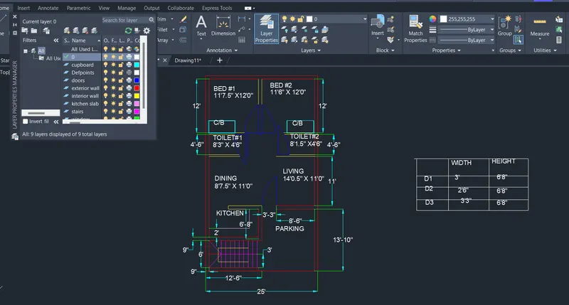
QUESTION 1: TO DRAFT THE RESIDENCE LAYOUT USING THE AUTOCAD:
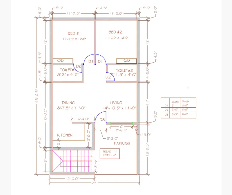
AIM : TO CREATE A RESIDENCE LAYOUT SEATING PLAN, TOILET AND UTILITY ROOM PLAN USING AUTOCAD.
INTRODUCTION:
Autocad offers various tools to perform different tasks. The various tools which are used for drafting in this project. These tools include construction line, trim, fillet, offset, layers, circle , rotate etc.
PROCEDURE:
STEP 1:
- Type LIMMAX and enter the value 100’,100 .
- Enter Z and Enter A.
- Enter units , select engineering and select precision 0;,0.0”.
- Enter limits and take lower limits 0’,0’ and upper limit is 70’,70’.
- Again enter Z and enter A.
- Click on layer properties in the layer panel.
- Click on a new layer to create the following layers like doors, exterior wall, interior wall, ventilator, cupboard, window, stairs, kitchen.
- Specify different colors on different layers.
STEP 2: EXTERIOR WALL:
- Using the construction line command in the XL horizontal and XL vertical was created.
- Press Esc to cancel the X line.
- As the thickness of the wall is 9’ and offset of 9 ‘ is created both vertically and horizontally.
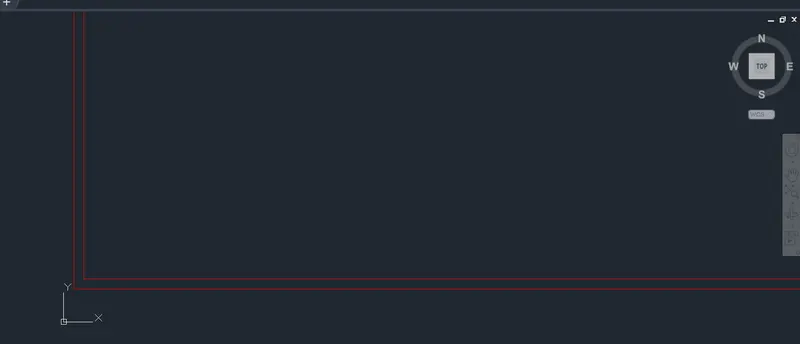
- The edges and corners are trimmed off and filleted to get the following images.
STEP 3:
- The horizontal outer line is offsetted to a distance of 43’65”.
- This line is again offsetted to a distance of 9’ that is the wall thickness.
- The vertical outer line is offsetted to a distance of 25’.
- This line is again offsetted to a distance of 9’ is the wall thickness.
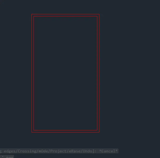
- The edges and corners are trimmed off or filleted.
STEP 4:
- The bottom inner horizontal line is offsetted to a distance of 6’ and the line formed is again offsetted to a distance of 9” as is the thickness of the external wall.
- The bottom outer horizontal line is offsetted to a distance of 139.5”’ and the line formed is again offsetted to a distance of 9” as is the thickness of the external wall.
- The left outer vertical line is offsetted to a distance of 12’6” and the line formed is again offsetted to a distance of 9” as is the thickness of the external wall.
- The vertical and horizontal construction lines are again offsetted, trimmed or filetted .
- Now all the external walls are completed.
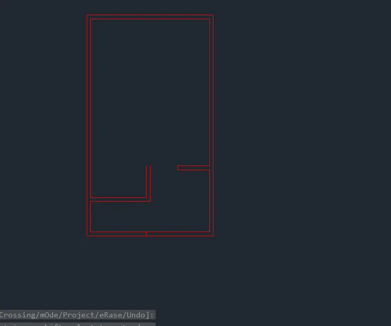
STEP 5: INTERIOR WALLS
- Select the internal wall layer as the default layer in the layer panel.
- The internal walls are created and the thickness of the internal wall is 4.5”.
- The edges of the corner after trimming and filleting.
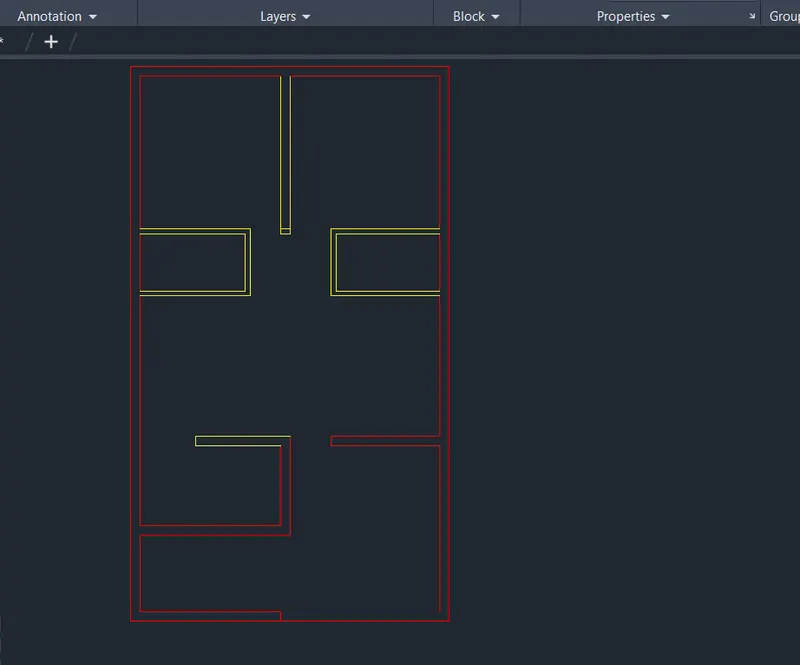
STEP 6: STAIR CASE
- Select the stairs layer as the default layer in the layer panel.
- Now using the line tool and offset tool staircase was drafted and the following image is obtained.
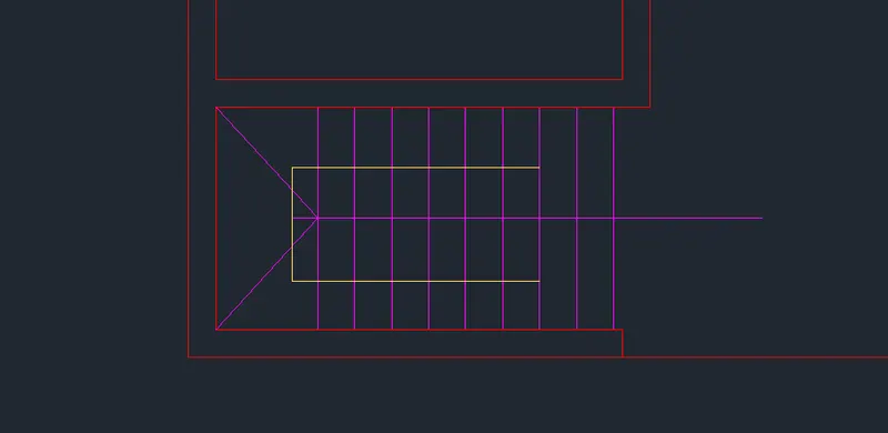
STEP 7: DOORS
- Select the doors layer created as the default layer in the layer panel.
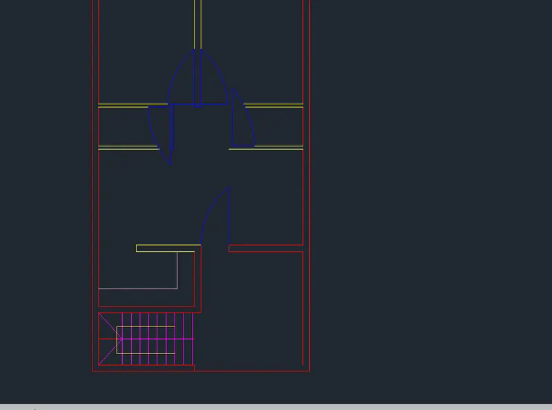
- Now using the line, arc, trim and offset tool doors of different sizes were drawn and the following image is obtained.
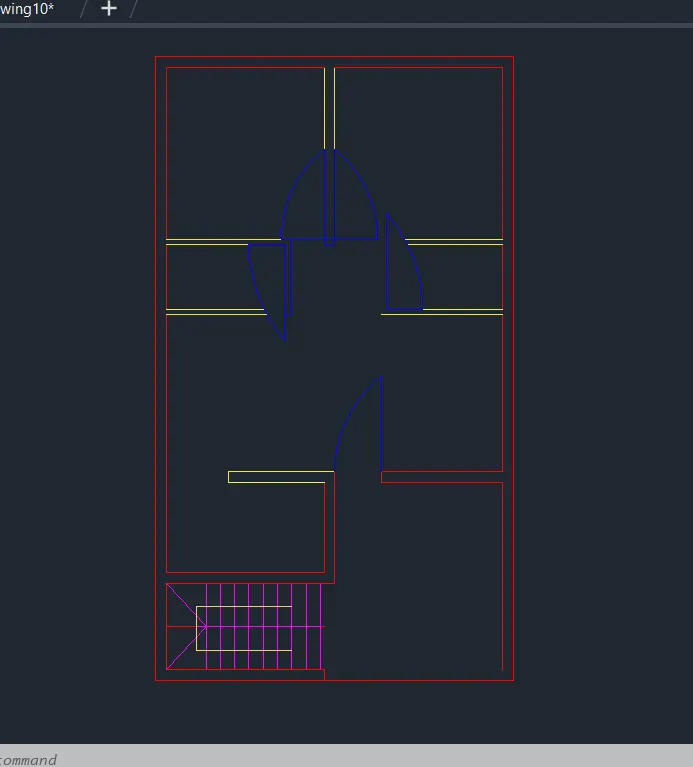
STEP 8: KITCHEN SLAB
- Select the kitchen slab as the default layer in the layer panel.
- Now using the offset tool kitchen slab was drawn and the following image is obtained.
STEP 9: CUPBOARD
- Select the cupboard layer as the default layer in the layer panel.
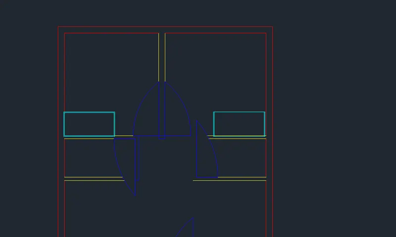
- Now using the rectangle and offset tool the cupboard was drawn and the following image is obtained.
RESULT:
---------------------------------------------------------------------------------------------------------------------------
QUESTION 2: TO DRAFT THE SEATING PLAN GIVEN BELOW USING AUTOCAD:
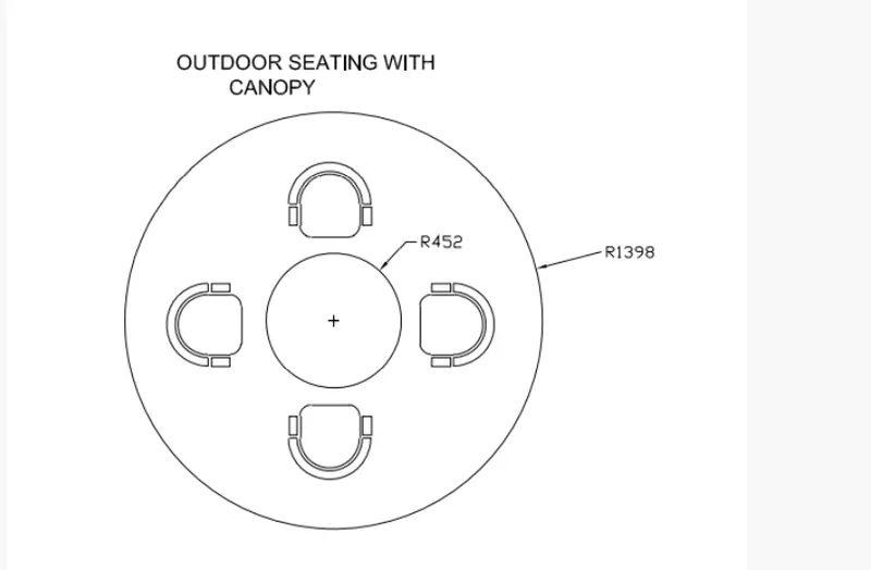
AIM : TO SKETCH THE SEATING PLAN FOR AN OUTDOOR CANOPY.
INTRODUCTION:
Autocad offers various tools to perform different tasks. The various tools which are used for drafting in this project . These tools include line, circle, arc , rectangle.
PROCEDURE:
STEP 1:
- Type units and enter.
- Select decimal and select precision 0 and enter.
- Now the lower limit is 0,0 and upper limit is 2500,2500.
- Type Z enters to zoom and A enters to all.
STEP 2:
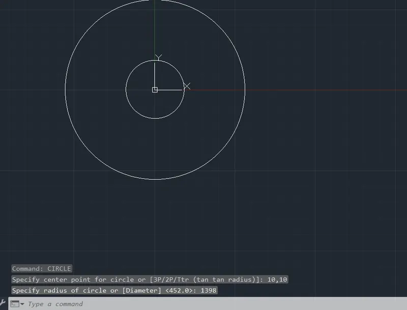
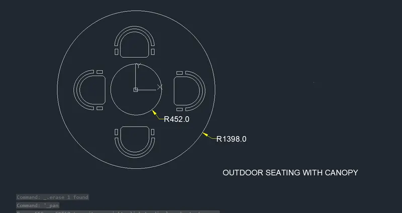
- Draw 2 circles of radius 1398mm and 452 mm with common radius.
- Type C and press enter.
- Specify center point of circle 10,10.
- Specify radius of circle 1398.
- Type c and press enter.
- Specify center point of circle 10,10.
- Specify radius of circle 452.
STEP 3:
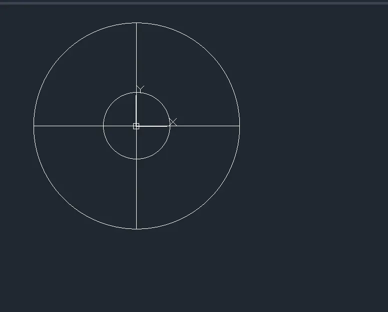
- From the center divide the circle into 4 quadrants by keeping the ortho mode on using the line command.
STEP 4:
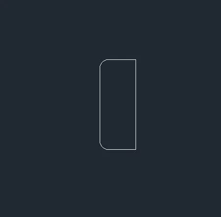
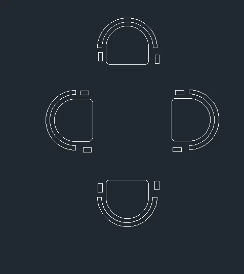
- To create the chair, first draw a rectangle of size 500 * 200 mm.
- Type RECTANG in the command line and press ENTER.
- Specify the first corner of the rectangle.
- Enter D for dimension.
- Enter the length = 200mm
- Enter the width = 500mm
- Specify the other corner.
STEP 5:
- Now select the fillet command in the command tab.
- select the first line to fillet with radius of 50mm.
- select the second line to fillet with radius of 50mm.
- press to cancel the filelt.
STEP 6:
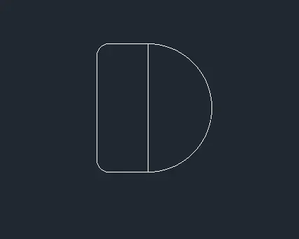
- Now draw an arc using the start, end radius command.
- Select the start, end radius option from the arc menu.
- Specify start point and end point of radius of arc is 250.
STEP 7:
- Trim of the unwanted lines and offset at a distance of 50mm is made of the chair handle.
- Type offset command in the command tab.
- Specify the value of an offset distance 50.
- Select the arc to offset and click outside the arc two times.
- And end of arc using the line tool.

STEP 8:
- Now type RECTANG in the command tab to draw the handle of the chair.
- Select the dimension of the rectangle.
- Specify the length of rectangle = 100mm
- Specify the width of the rectangle = 50 mm
- Trim the unwanted lines of the drawing.

STEP 9:
- Now using the copy command in the command tab.
- The chair was copied and placed once.
- Using the rotate command one chair is rotated 90 degrees.
- Using the mirror command both the chairs were mirrored and by keeping the source object.
STEP 10:
- Now using the move command in the command tab.
- The chairs were placed on quadrant lines which were made earlier centrally.
- Trim off the quadrant lines after placing the chairs.
- Now dimension is provided.
---------------------------------------------------------------------------------------------------------------------------
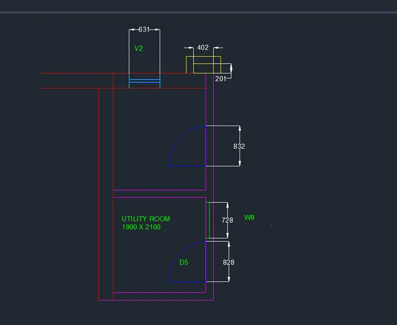
QUESTION 3: TO DRAFT THE TOILET AND UTILITY ROOM GIVEN USING AUTOCAD:
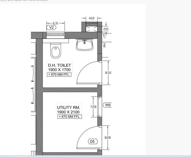
AIM: TO DRAFT THE TOILET AND UTILITY ROOM GIVEN USING AUTOCAD.
INTRODUCTION:
Autocad offers various tools to perform different tasks. The various tools which are used for drafting in this project . These tools include line, arc , rectangle.
PROCEDURE:
STEP 1:
- Type units and press enter.
- Under drawing units select decimal.
- Now the lower limit is 0,0 and upper limit is 2500,2500.
- Type Z enters to zoom and A enters to all.
STEP 2: EXTERIOR WALLS
- Select the exterior wall layer as the default layer in the layer panel.
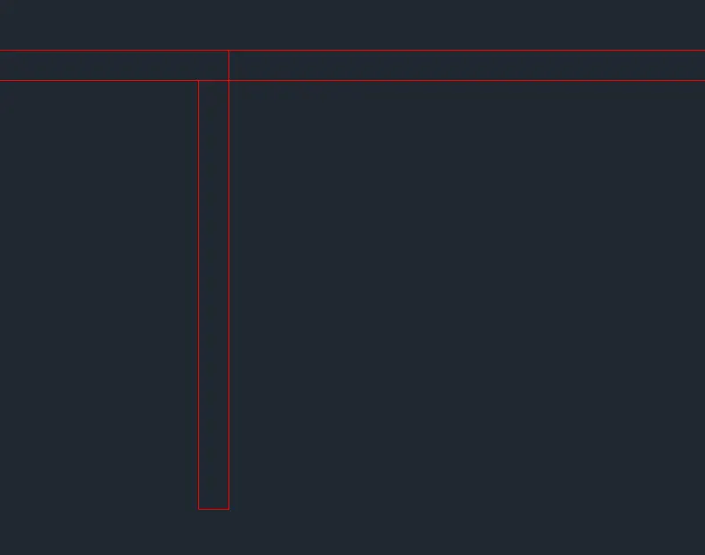
- Select the construction line tool by entering XL line command in the command tab.
- Draw two lines, one is horizontal and the second one is vertical.
- Select the offset tool by entering OFFSET command in the command tab.
- The thickness of the external wall is 300mm at offset distance 300 in the command line.
- Select both the vertical and horizontal lines.
- Next offset the inner horizontal line to a distance of 4250.
- This line is again offset by an offset distance of 300mm.
- Select the trim tool by trimming the extra line of the drawing.
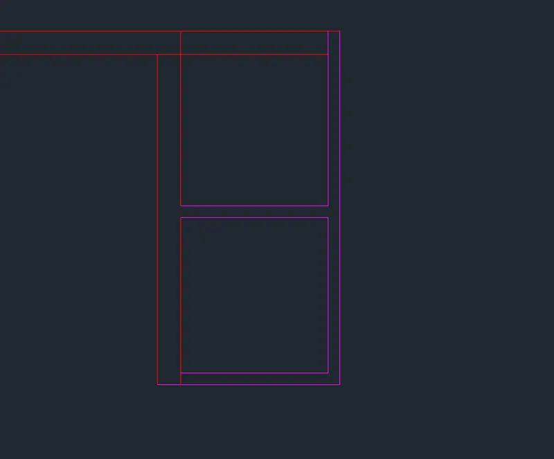
STEP 3: INTERIOR WALL
- Select the interior wall as the default layer in the layer panel.
- Select the construction line XL line command in the command tab.
- Draw two lines, one is horizontal and the second one is vertical.
- Select the offset tool by entering the OFFSET command in the command tab.
- Thickness of the internal wall is 150mm and the offset distance is 150mm.
- Specify the next point of offset of the inner horizontal and take the offset distance is 2100.
- Again this line offsetted by 150mm offset distance.
- Specify the next point of offset of vertical horizontal and take offset distance is 1900.
- Again this line is offsetted by 150mm offset distance.
- Select the trim tool by trimming the extra lines of the drawing.
STEP 4: DOORS
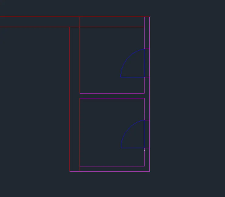
- Select the doors by default layer of the layer panel.
- Select the line tool by entering LINE COMMAND in the command tab.
- Draw a line and take a width of 828 and draw an arc of the arc panel and select the start, end , direction and draw an arc.
- Again select the line tool by entering LINE command in the command tab.
- Draw a line and take a width of 832 and draw an arc of arc panel and select the start, end, direction and draw an arc.
STEP 5: WINDOWS AND VENTILATOR
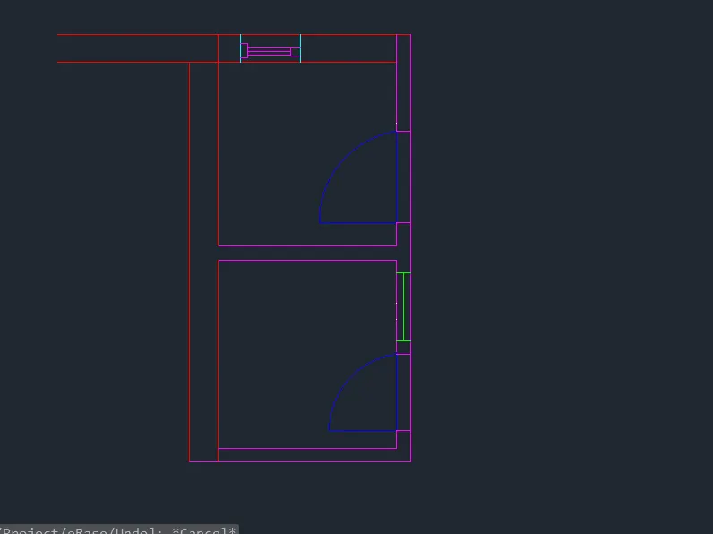
- Select the window layer as the default layer in the layer panel.
- Select the line tool by entering LINE command in the command tab.
- Draw a line and take an offset of that line at a distance of 728.
- Then take a line to join these lines.
- Select the ventilator layer as the default layer in the layer panel.
- Again take a line tool by entering LINE command in the command tab.
- And draw a line and take the offset of that line at a distance of 631.
- And joining these lines.
STEP 6: DUCT
- To draw a duct layer as the default layer in the layer panel.
- Select the rectangle tool by entering RECTANGLE command in the command tab.
- Specify the dimension of the rectangle.
- Specify the length of the rectangle = 402.
- Specify the width of the rectangle = 201.
- Select the offset tool by taking an offset distance 150mm in the rectangle drawing.

RESULT :