Creating a Layout, Section and Elevation with dimensions using AutoCad
Aim:
Creating a Layout, Section and Elevation with dimensions using AutoCAD.
Introduction:
Create the Plan and Sections as shown in the Figures. Use proper dimension techniques and dimension styles to document the project. Assume the sizes of the doors and windows as per construction standards. Refer to sections for stair details if required.
Command Used:
- Xline
- Line
- Rectangle
- Circle
- Fillet
- Offset
- Mirror
- Trim
- Extend
- Mtext
- DIM
- Erase
Steps:
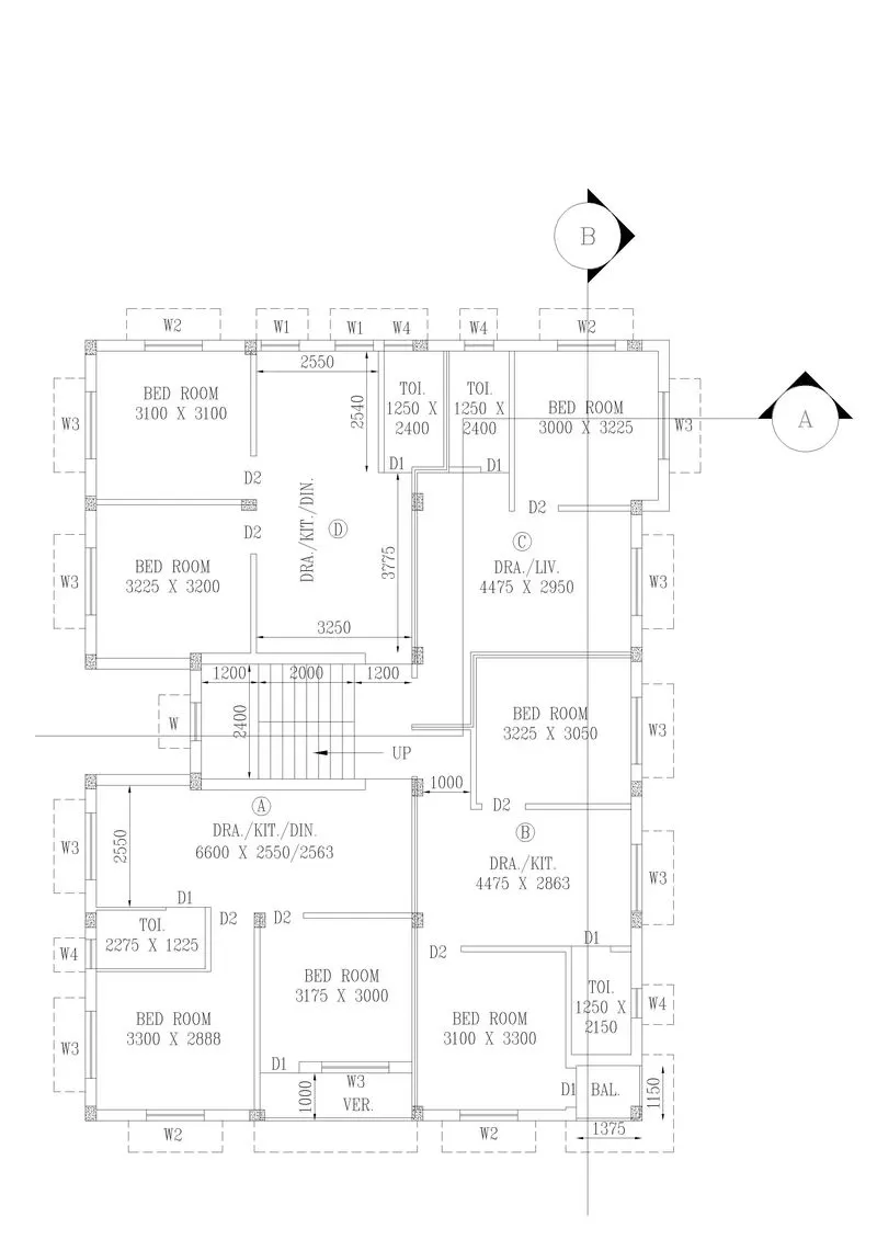
- Draw the X lines and Fillet and draw all the walls given in the figure.
- Draw all the column and hatch the columns , placement of columns as per the given figure.
- Now annotate all the doors and windows as given.
- Now annotate all the rooms sizes and the dimension given in the figure.
- Now draw the section lines as given in the figure.
- Final Figure First
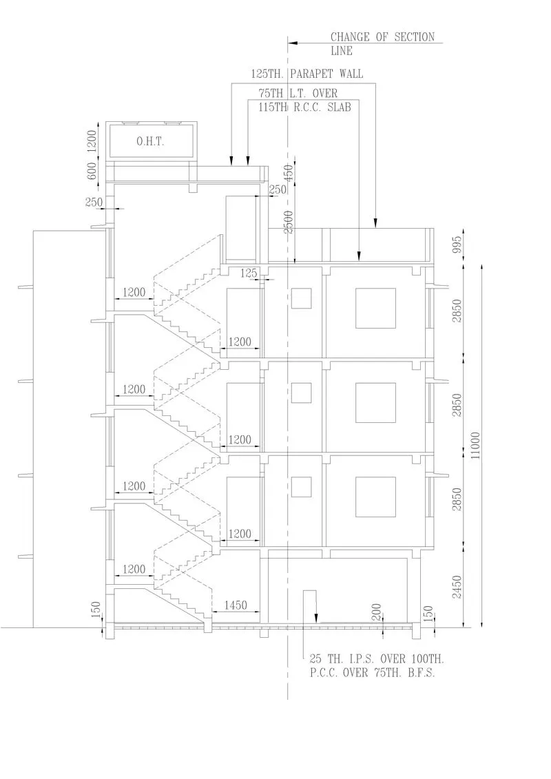
- Now, Draw Section AA as given and provided details.
- Now Annotate the provided dimensions as per the given figure.
- Now draw the Change of section line as given.
- Now annotate the Leader text as given.
- Final Figure Second
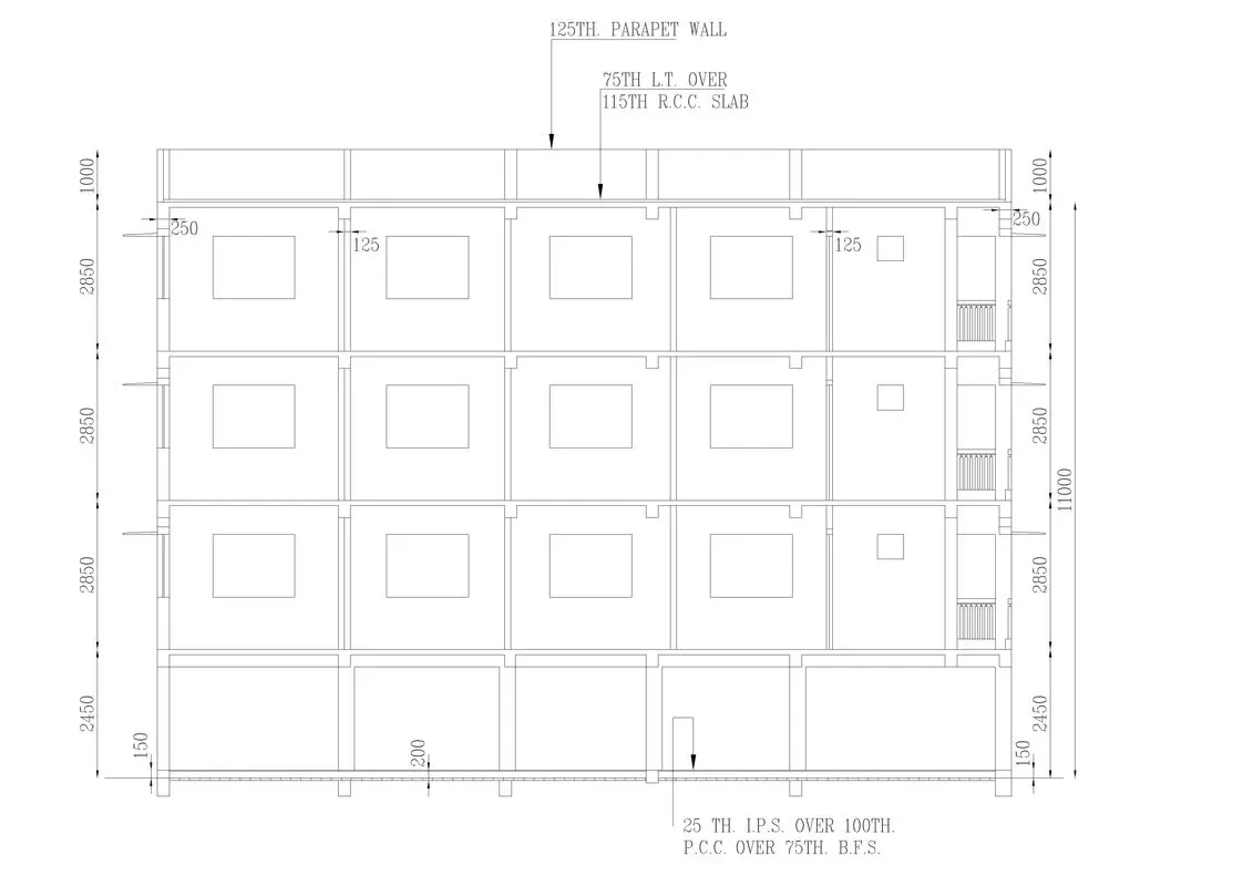
- Now, draw the section BB layout.
- Now Annotate all the dimension as per the given figure.
- Now Annotate the details mentioned in the given figure.
- Final Figure Third
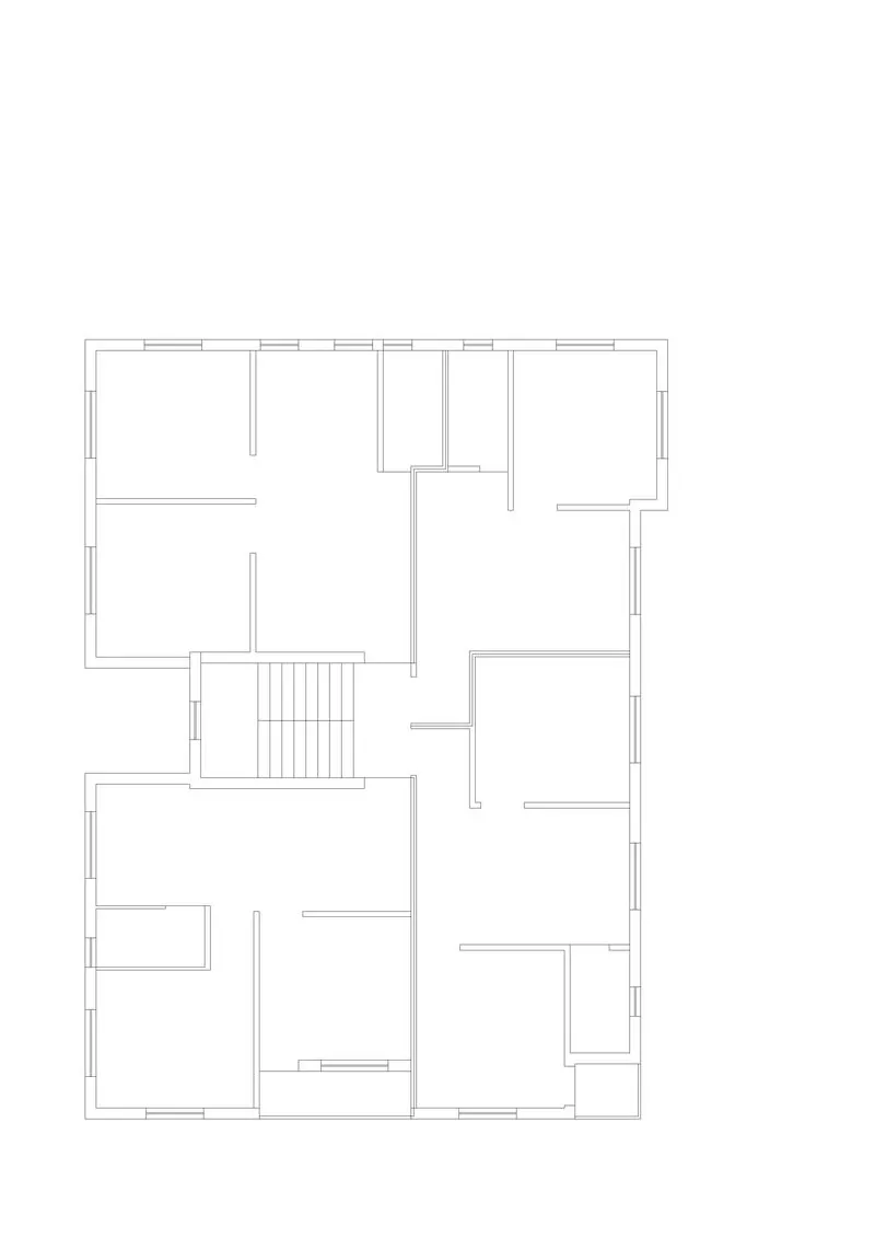
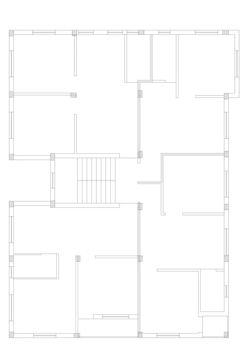
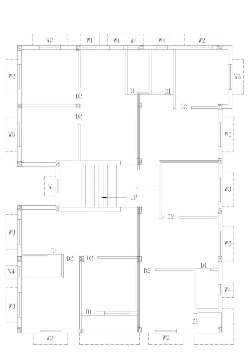
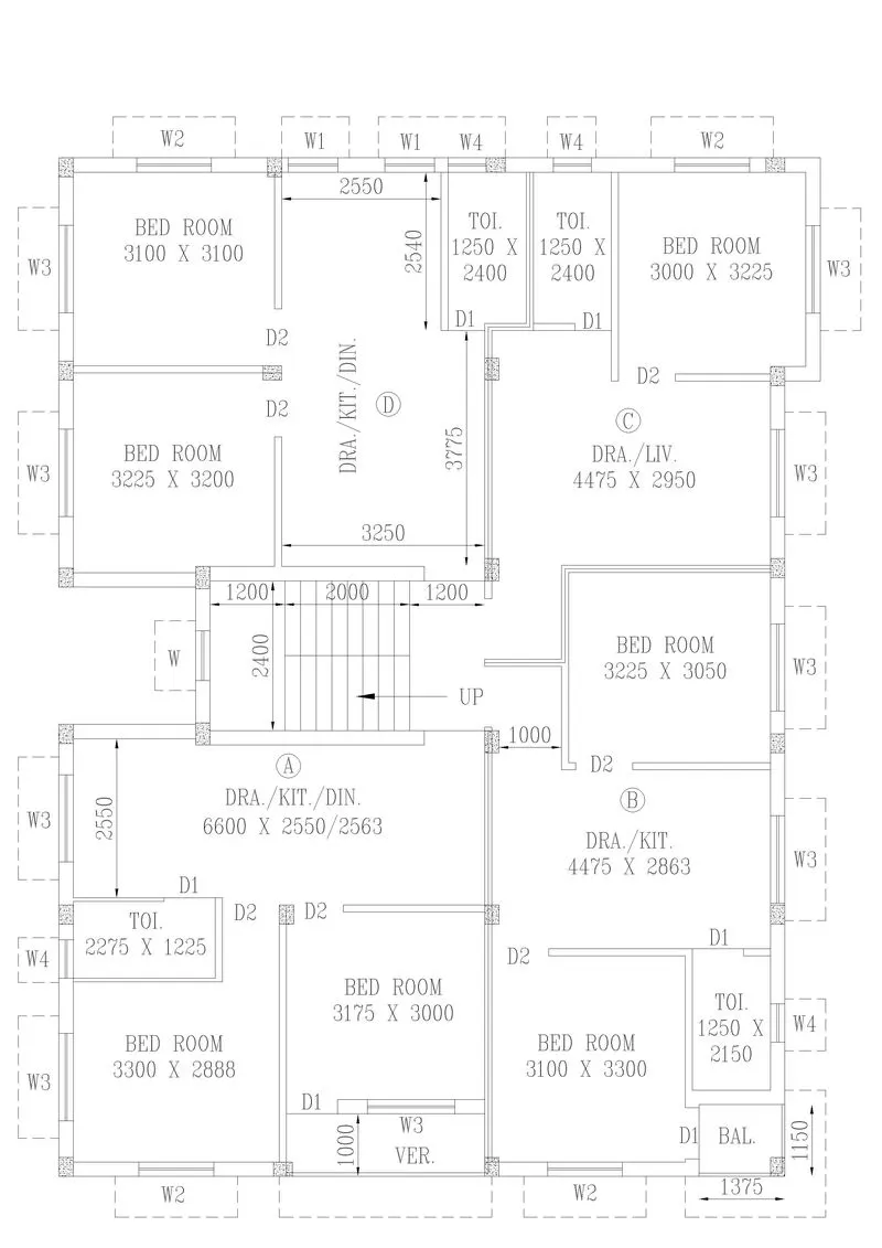
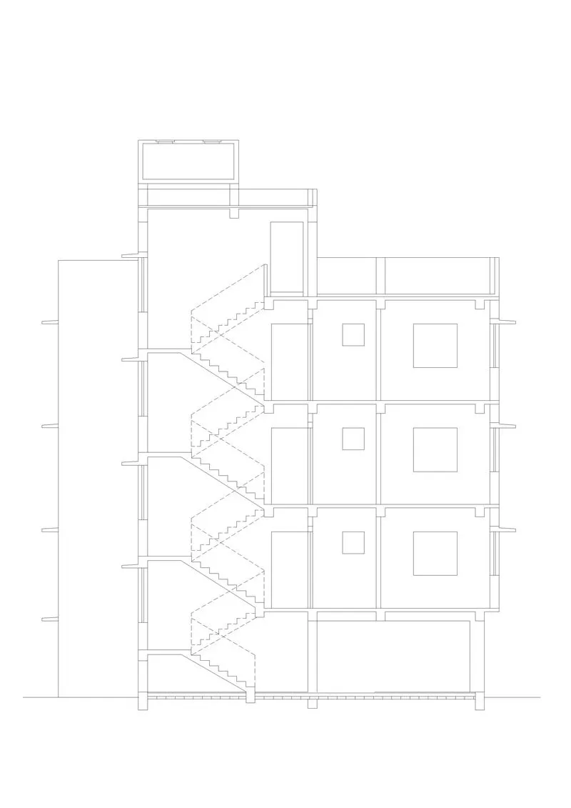
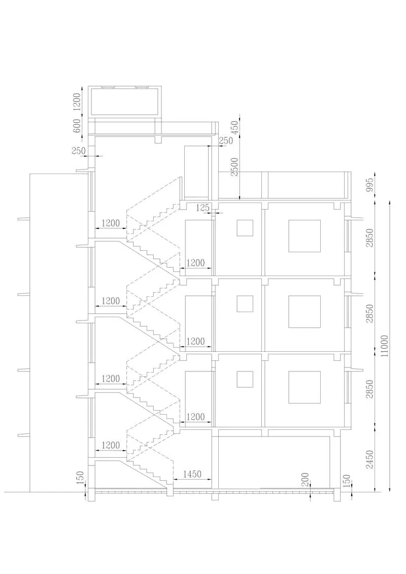
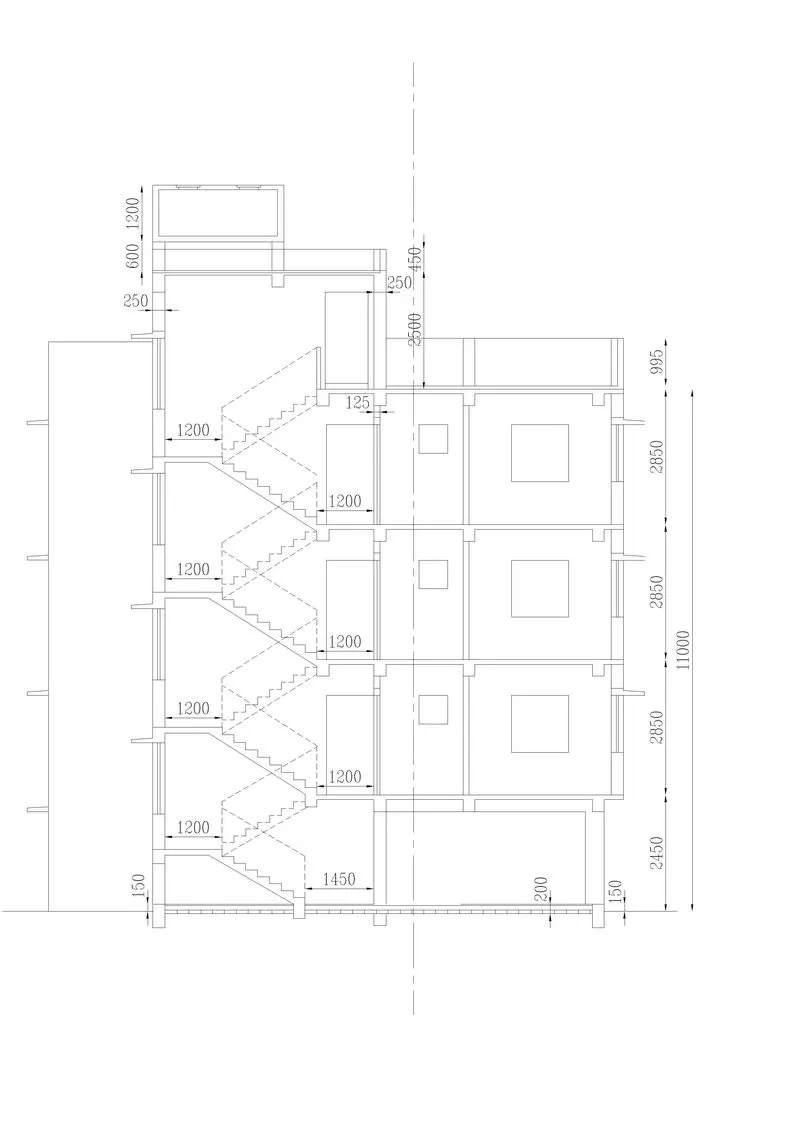
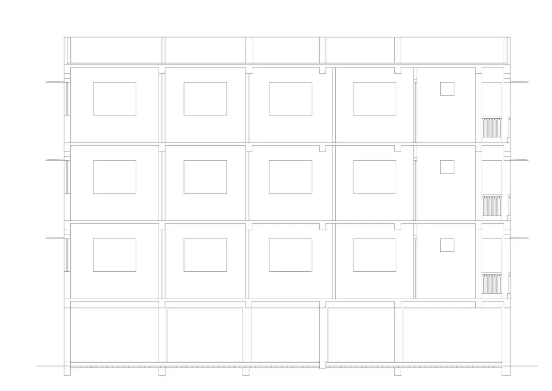
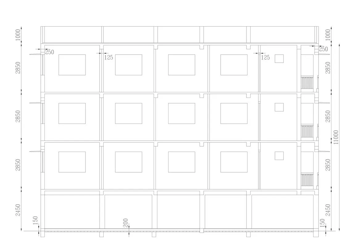
Final Figures :
Result:
All the Layout, Section and Elevation with dimensions using AutoCAD is successfully drawn.