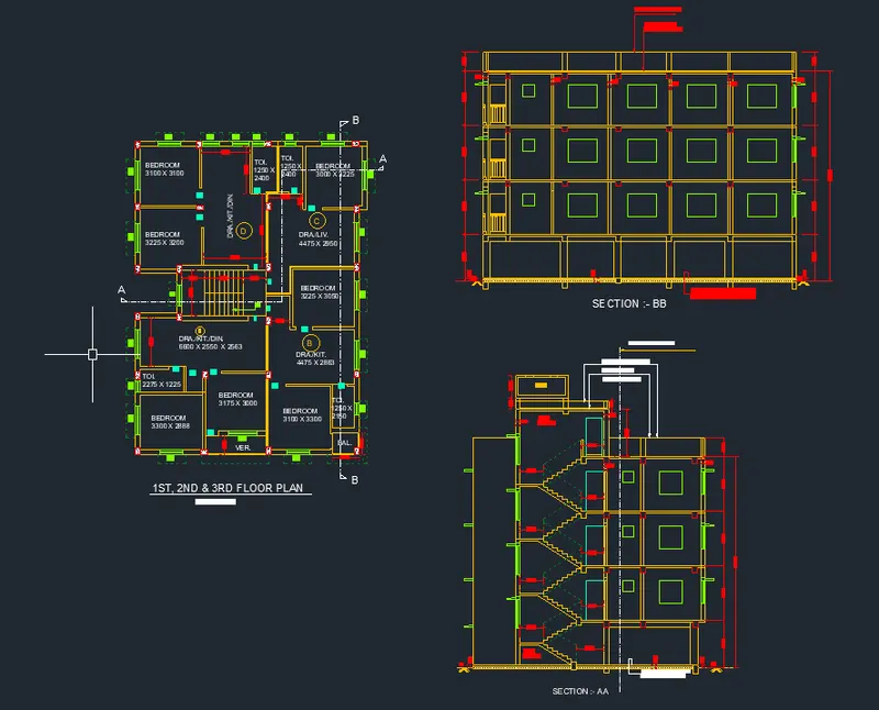
Creating a Layout, Section and Elevation with dimensions using AutoCad
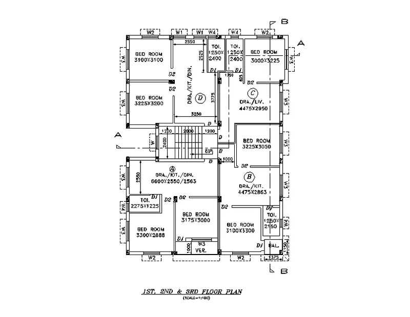
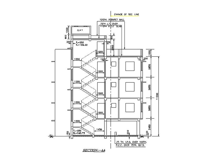
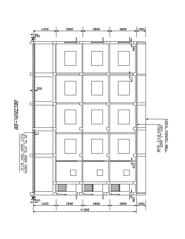
AIM : Create the Plan and Sections as shown in the Figures.
INTRODUCTION :
floor plans are made irrespective of the fact that they are to be utilised during the construction project. it include an understending nof the dimensions and different kind of installement. sections allow the architect to look at the different component of a building verrtically.
in this drawing we have Used proper dimension techniques and dimension styles to document the project. we have Assumed the sizes of the doors and windows as per construction standards. Refer to sections for stair details if required.
PROCEDURE :
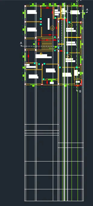
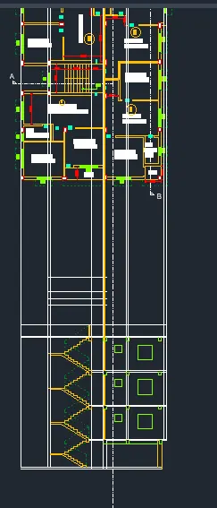
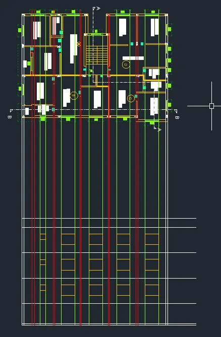
1. FLOOR PLAN
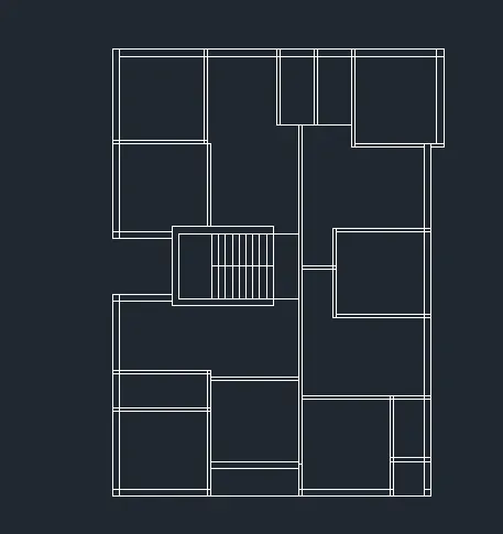
step-1 :
- set unit to decimal milimeter.
- type xline and make xline in x-direction and y-direction
- set layers for walls, window, door, dimensions etc.
- take exterior walls thicknes as 250mm aand interior walls as 125mm
- take offset of 250mm to xlines
- using given dimensions make offset properly to set rooms.
- use fillet, trim, offset, etc command
step-2 :
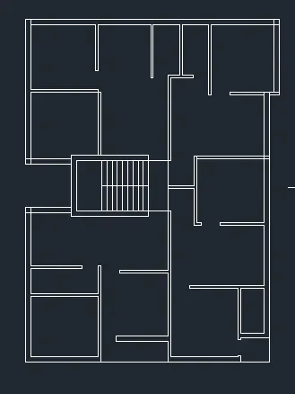
- give openong of doors
- assume door sizes
D= 1200 X 2100
D1= 750 X 2100
D2= 900 X 2100
- using trim , ofset and line command give openings to rooms
- for some places adjust wall thickness for door opening because we dont know proper dimensions of given drawing.
step-3 :
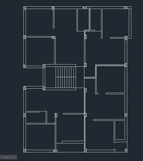
- as we dont know the column position measurement so we have to take reference
- import pdf of given drawing
- scale pdf using reference option
- paste this pdf on actual drawing
- mark all the column position properly adjust the distance properly
- using hatch ansi concrete hatch the columns
- scale hatch
step-4 :
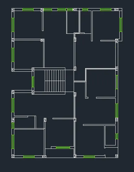
- set windows
- first we need to assume width of different window
W= 1100
W1= 900
W2= 1200
W3=1500
W4= 600
- take reference of pdf and set windows position
- use copy command
step-5 :
- i have given layers to different sections
- give chajja projections
- make layer of linetype dash space , scale it
- use this layer mark chajja projection
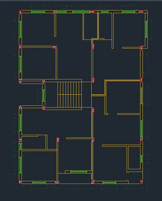
step-6 :
- make layer for section line
- use linetype centerline and give white colour
- using pdf reference mark section line on drawings
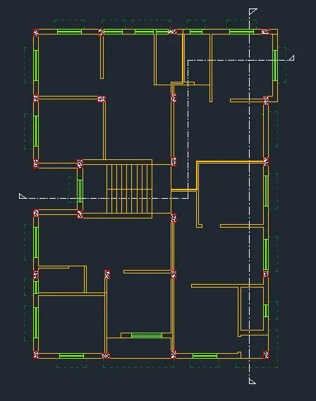
step-7
- use mtext command for naming the drawings
- use dimlin command for dimensions
- use dimstyle for editing dimensions
- use multileader command to draw arrows and naming
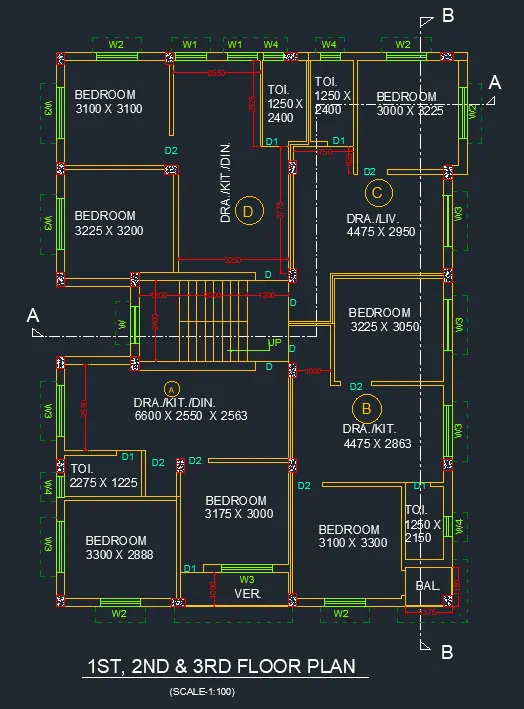
- lastly check up the drawing for mistakes or anything left
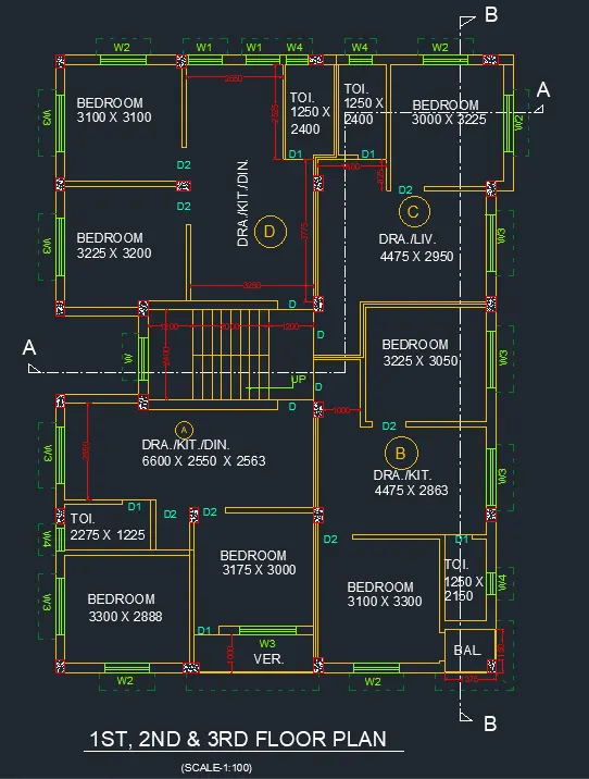
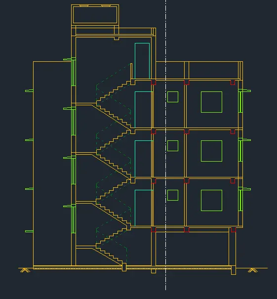
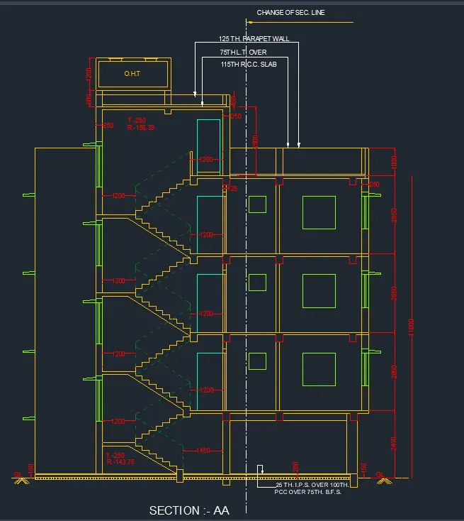
2. SECTION- AA
step-1 :
- keep unit same as above drawing
- using xline command make vertical projection line for drawing sections
- take any horizontal base line using xline command and start the drawing from bottom
- from this base line make offset of 2450, 2850, 2850, 2850, 1000, as given in figure
- trim unwanted xlines projection
step-2 :
- import the pdf scale it and paste it on actual drawing
- convert this pdf into single layer ao that we can turn off anytime
- mark the window position and column positions
- draw the section line
- draw the staircase section
- here for gf staircase take tread-250mm and riser-143.75
- above gf use treaf - 250mm and riser - 158.33
- use path array for drawing riser and tread maintain in betwwen distance
- maintain side distance from wall and door
- use linetype dashspace for projections of staircase
step-3 :
- draw the doors as we assume the sizes of door
- draw section line
- at bootom line give offset of 200 below the line
- now on the offset line give offset 75, then 100 and then 25
- between 75 thickness offset draw the hatch ANSI31
- i have scale the hatch set angle and scale for it
- usig pdf reference i have drawn other part of drawing which is not possible by other way.
step-4 :
- use mtext command , qleader or multileader command give the name for differenr component
- change text height wherever required
- use dimlin for dimensions and dimstyle command for dimension editing
- give the name and dimension to drawings
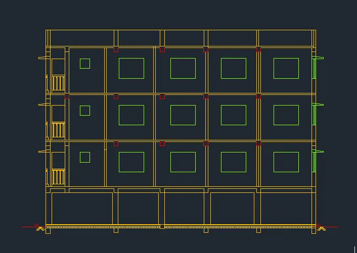
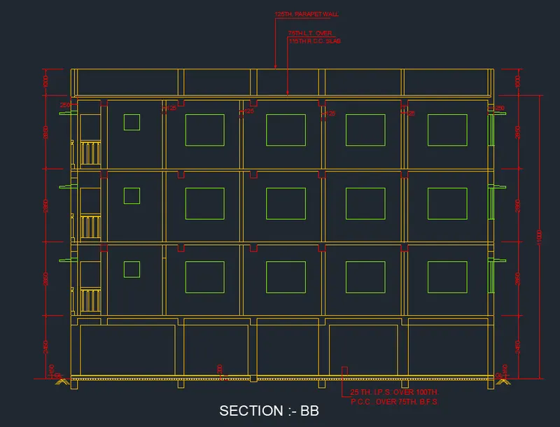
3.SECTION- BB.
step-1:
- in this drawing the given sketch doesnt show properly so for reference we need to position it properly
- keep the unit same as in both the above drawings
- using xline mark the vertical projections of each component cutting in section-BB
- take any baseline as in xdirection at bottom so that we can take offset from it
- mark first offset of 150 below the line
- from this 150 offset line start then giving offset in continuous as length 2450, 2850, 2850, 2850, 1000
- draw windows using this projection line
step-2 :
- trim the unwanted xline
- wall thickness 250 and 125 mm
- draw the walls positon and using trim erase unwanted lines
- give slab thickess as 100mm and using offset command
- draw the other component of drawing using line command
- draw chajja and window position
- draw the beam marking shown in red colour
- at bottom 2nd last line from bottom give a 200 offset below the line
- from this line give 75 offset above then 100 and then 25
- between 75mm distance hatch it using ANSI31
- edit the hatching
step-3 :
- use mtext command , qleader or multileader command give the name for different component
- change text height wherever required
- use dimlin for dimensions and dimstyle command for dimension editing
- give the name and dimension to drawings
RESULT :
we have Created a Layout, Section and Elevation with dimensions using AutoCad.