Creating a Layout, Section and Elevation with dimensions using AutoCad
1.Aim: To create the plan of a building in the Auto cad using decimal system.
- In a particular building plan is very important module and it is the top view of the building or any other unit.
- The plan gives the two dimensions of the building unit and the orientation of the building with the geographic conditions.
- The plan gives the details of a single floor at a time.For different levels of the building the plan may be changed according to the various levels.
Procedure :
- Click on new File and create the new template for potting the drawing.
- Now enter units (un) command and select the decimal system in the units and also set the precision of the units and insertion scale to mm and click on ok.
- To create theplan of the building first we neeed to fix the geoghraphic directions to gett the orientation of the building and later fix the one of the extreme corner of the building by using the construction lines in horizontal and vertical directions the intersection between the two lines will give the extreme edge of the building.
- Then using the off set command fix the wall thickness with an offset distance 230mm create the wall.
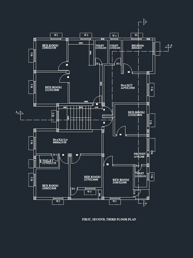
- Now enter the ploy line command and trck the distance at the inner edge of the wall and plot the room of size 3100x3100.
- Now using the offset command create the wall with an off set distance of 150mm.Now again enter the poly line command and track the point at a distance of 2550 plot the room of size of 2550x2550 and also create the wall using the offset command to an offset distance of 150mm.
- Enter the poly line command track the distance of 3225 inthe vertically downward direction and plot the room of size 3225x3000 and create the wall with the offset command and create the wall at the offset thickness of 230mm on horizontal direction and 150mm onthe vertical direction.
- Now using the poly line comannd we can track the distance of 1250 and plot the wall at a distance of 2400 in the vertical direction and also create the wall at a thickness of 150mm.Now using the copy command copythe wall to a distance of 1250mm in the horizontal direction and it will create the two toilet rooms of equal size.
- Now again enter the poly line command and track the diatance of 3000mm and plot the room of size 3000x3225 and using the offset command create the wall at a distance of 230mm.This will fix the another extreme edge of the plan.
- Now using the trim command trim the intersection lines in the wall and using the poly line command plot the columns at a size of 230x300 at all the corners and also at the required places.
- We can observethat the column is slightly away from the wall corner in the extreme right of the plan and using the poly line commnad track the distance from the right end and fix the column in the horizontal direction.
- Now again using the polyline command we can plot the right side wall at a time by adding all the room dimensions this will help to reduce the time instead of plotting the each room.
- Now add th all the room widths and along with the wall thickness plot the line in the vertical direction.
- Now usingthe offset command we can plot the wall thickness at a distance 230mm or 150mm as we required.
- Now from the top edge using the offset command we can create the each room changing the off set distance the offset can be done either from the extreme top wall or from the wall lines of the individual rooms.
- Enter trim command and trim the wall intersection lines and create the edges of the walls and plot the columns at a size of 230x300 at the required orientation and position of the columns.
- Now again using the polyline command we can plot the bottom side wall at a time by adding all the room dimensions this will help to reduce the time instead of plotting the each room.
- Now add the all the room linear dimensions and along with the wall thickness plot the line in the horizontal direction.
- Now usingthe offset command we can plot the wall thickness at a distance 230mm or 150mm
- Now from the extreme right edge of the building edge using the offset command we can create the each room changing the off set distance the offset can be done either from the extreme left wall or from the wall lines of the individual rooms.
- Enter trim command and trim the wall intersection lines and also the wall at the balcony will be trimmed and create the edges of the walls and plot the columns at a size of 230x300 at the required orientation and position of the columns.
- Now again using the polyline command we can plot the left side wall at a time by adding all the room dimensions this will help to reduce the time instead of plotting the each room.
- Now add the all the room widths and along with the wall thickness plot the line in the vertical direction.
- Now usingthe offset command we can plot the wall thickness at a distance 230mm or 150mm
- Now from the extreme left edge of the building edge using the offset command we can create the each room changing the off set distance the offset can be done either from the extreme left wall or from the wall lines of the individual rooms.
- Enter trim command and trim the wall intersection lines and also the wall at the balcony will be trimmed and create the edges of the walls and plot the columns at a size of 230x300 at the required orientation and position of the columns.
- The Stair can be created at a equal size of treads using the off set or copy or line command
- Now cretae the doors D1(750x2100)and D2 (1000x2100) as blocks and insert the doors at all the rooms and toilets.
- Now again create the windows and ventilators W1(1000X1500),W2(1000X1500),W3(1200X1500),W4(700X500) create the blocks and insert the blocks at all the rooms and toilets and also at the stair case.
- Now using the hatching command 'H' enter in the command bar the walls,doors,windows, beam and column projections are hatched.
- Hatching specifies the mode of material to be used for making the architectural view of the building or car case.
- Now dimlinear command the dimensions of the plan are plotted,it will be useful if we create the new dimension style.
- Create a new text style by entering 'ST'command in the comand bar.
- Now using text or mtext command the elevation details are written to specify the different items of the model.
- Now using the layers command assign layers to the various units of the elevation model as we required.
- The final result of the plan of the bulding is obtained as shown inthe below.
Aim: To create the section of a building in the Auto cad using decimal system.
- In a particular building plan is very important module and it is the cutting view of the building or any other unit.
- The section gives the two dimensions of the building unit and out of them height will be common and the other dimension is either length or width of the building unit.
- The section gives the profile of the building of materilal or internal view details of a various floors at a time.Sectional views may change according to the cutting sections of the building.
Procedure :
- Click on new File and create the new template for potting the drawing.
- Now enter units (un) command and select the decimal system in the units and also set the precision of the units and insertion scale to mm and click on ok.
- To create the section we need to cut plan at at a particular direction either X or Y axis of the plan.
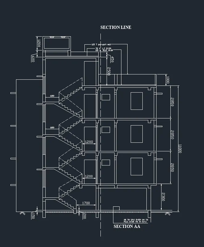
- The section AA is cut in the x axis direction and in this plan there is no change in the first second and third floors so the sectional view will be same for the first,second,third floors and the sectionview of the ground floor willbe different.
- For the sectional view we need to fix the outer edges of the building with the length or width can be plotted with reference to the plan and the height of the building can be plotted by adding the floor heights,foundation thickess and any other units on the terrace of the building.
- For the section AA the length with reference from the plan can be plotted and the height is plotted using the offset command.
- Enter the off set command and at offset distance of 2450 the slab line of the ground floor is plotted.
- Again enter the off set command and at a off set of distance of 2850 the slab line of the first floor is plotted and the second and third floor is plotted by copying the first floor after all the interiors are plotted.
- Again enter the off set command and at an offset distance of 150mm slab thickness the slab is plotted for the first and ground floors.
- Now using the off set comand plot the column lines in the first and ground floors at the required distance obtained from the plan from the right edges of the building.
- Inthe same way using the poly line command we can plot the beam in the first and ground floors over the columns to a size of 230x230mm and 250x230mm and also at the places where the beams are being cut by the section line.
- Now using the trim command trim the unwanted lines at the junction of columns beams and slab.
- Now the stair case is plotted by the appropraite angle, the cutting line is passed along the middle of the one of the flights so the sectional view shows the profile of the stair of the one flight and the other flight shows the mirrior lines of the flight.
- After completion of the ground and first floor using the copy command the first floor is copied to height of 2850 from the top slab line of the first floor as the second and third floor will resemble the same size as that of the first floor.The minor may changes may be changed in the second and third floor if required any.
- Now the internal view of the room either windows or the ventilators is plotted with refence to the slab level.
- The lintel and chujja projections will be plotted according to the slab level of the floors.
- Now after completion of the ground and first floor the second and third floors will be copied with reference to the first floor.
- The overe head tank on the top of the slab is plotted by the polyline command or the rectangle command.
- The parapet wall is plotted by using the poly line command to a height of 1000mm.
- Now using the hatching command 'H' enter in the command bar the walls,doors,windows, beam and column projections are hatched.
- Hatching specifies the mode of material to be used for making the architectural view of the building or car case.
- Now dimlinear command the dimensions of the plan are plotted,it will be useful if we create the new dimension style.
- Create a new text style by entering 'ST'command in the comand bar.
- Now using text or mtext command the elevation details are written to specify the different items of the model.
- Now using the layers command assign layers to the various units of the elevation model as we required.
- The final result of the section AA view of the bulding is obtained as shown inthe below.
Aim: To create the section of a building in the Auto cad using decimal system.
- In a particular building plan is very important module and it is the cutting view of the building or any other unit.
- The section gives the two dimensions of the building unit and out of them height will be common and the other dimension is either length or width of the building unit.
- The section gives the profile of the building of materilal or internal view details of a various floors at a time.Sectional views may change according to the cutting sections of the building.
Procedure :
- Click on new File and create the new template for potting the drawing.
- Now enter units (un) command and select the decimal system in the units and also set the precision of the units and insertion scale to mm and click on ok.
- To create the section we need to cut plan at at a particular direction either X or Y axis of the plan.
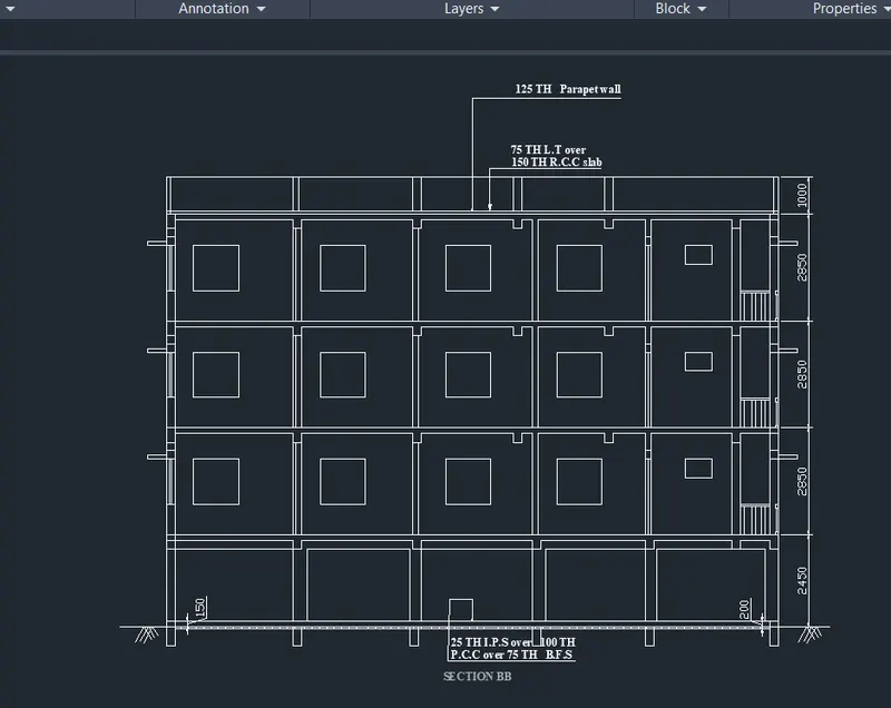
- The section BB is cut in the Y axis direction and in this plan there is no change in the first second and third floors so the sectional view will be same for the first,second,third floors and the sectionview of the ground floor willbe different.
- For the sectional view we need to fix the outer edges of the building with the length or width can be plotted with reference to the plan and the height of the building can be plotted by adding the floor heights,foundation thickess and any other units on the terrace of the building.
- For the section BB the length with reference from the plan can be plotted and the height is plotted using the offset command.
- Enter the off set command and at offset distance of 2450 the slab line of the ground floor is plotted.
- Again enter the off set command and at a off set of distance of 2850 the slab line of the first floor is plotted and the second and third floor is plotted by copying the first floor after all the interiors are plotted.
- Again enter the off set command and at an offset distance of 150mm slab thickness the slab is plotted for the first and ground floors.
- Now using the off set comand plot the column lines in the first and ground floors at the required distance obtained from the plan from the edges of the building.
- Inthe same way using the poly line command we can plot the beam in the first and ground floors over the columns to a size of 230x230mm or 250x230mm and also at the places where the beams are being cut by the section line.
- Now using the trim command trim the unwanted lines at the junction of columns beams and slab.
- Now the internal view of the room either windows or the ventilators is plotted with refence to the slab level.
- The lintel and chujja projections will be plotted according to the slab level of the floors.
- Now after completion of the ground and first floor the second and third floors will be copied with reference to the first floor.
- Th parapet wall is plotted with the poly line command to height of 1000mm and the length is along the sectional length of the building unit.
- The railing of the balcony is plotted with the poly line command to a height of 700mm along the length of the balcony in the sectional view of the building unit.
- After completion of the ground and first floor using the copy command the first floor is copied to height of 2850 from the top slab line of the first floor as the second and third floor will resemble the same size as that of the first floor.The minor may changes may be changed in the second and third floor if required any.
- Now using the hatching command 'H' enter in the command bar the walls,doors,windows, beam and column projections are hatched.
- Hatching specifies the mode of material to be used for making the architectural view of the building or car case.
- Now dimlinear command the dimensions of the plan are plotted,it will be useful if we create the new dimension style.
- Create a new text style by entering 'ST'command in the comand bar.
- Now using text or mtext command the elevation details are written to specify the different items of the model.
- Now using the layers command assign layers to the various units of the elevation model as we required.
- The final result of the section BB view of the bulding is obtained as shown inthe below.