Creating a Floor plan, Footing detail and Isometric view using AutoCad
1.AIM
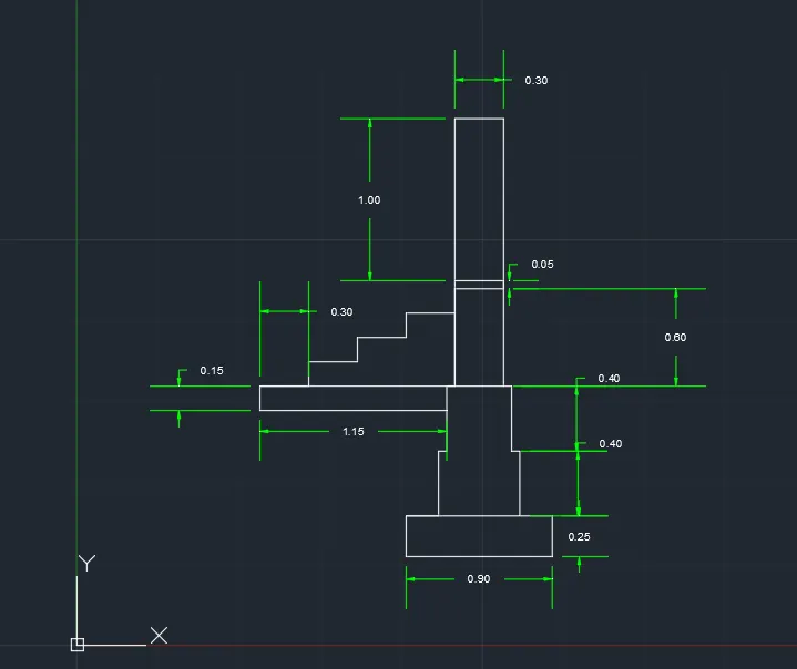
To draw the cross-section of Load bearing wall over spread footing to use the software of Auto CAD.
PROCEDURE
- To open the new sheet and type,, U’’ in command bar to change the units into meters.
- Type,,L’’ to give the line command and to give the dimensions to the command, the line was drawn. Indicate the direction of the line by line keeping ortho in ON.
- To check the all given dimension, then we decide the need command to draw the perfect diagram.
- Type,,C’’ for close the every particular dimensional objects in a perfect.
- Type ,, DT’’ command to write the text at any part of the footing.
- Type ,, DLI’’ command for to give the dimensions of each particular part, after finishing the drawing work .
- To save the file, go to the auto cad application to choose the save option.
RESULTS
The diagram of the given cross section of load bearing wall over spread footing is drawn as per dimension using Auto CAD Software.
DIAGRAM
2.AIM
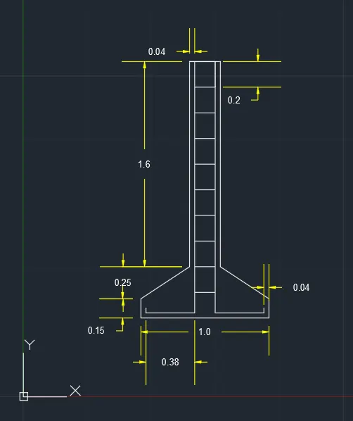
To draw the cross-section of ISOLATED FOOTING to use the software of Auto CAD.
PROCEDURE
- To open the new sheet and type,, U’’ in command bar to change the units into meters.
- Type,,L’’ to give the line command and to give the dimensions to the command, the line was drawn. Indicate the direction of the line by line keeping ortho in ON.
- Type ,,O” for the offset command and type the dimensions as 0.20m, then check. Inside, where parallel line is required.
- Type ,,Tr ’’ for trim command, to trim the extra lines after the dimensions.
- Type,,C’’ for close the every particular dimensional objects in a perfect.
- Type ,, DT’’ command to write the text at any part of the footing.
- Type ,, DLI’’ command for to give the dimensions of each particular part, after finishing the drawing work .
- Finally, adopting the above all commands are drawn with dimension with a text.
- The size of dimensions and the size of the arrows can be changed by typing the DDIM in command bar.
RESULTS
The diagram of the given cross section of ISOLATED FOOTING is drawn as per dimension using Auto CAD Software.
DIAGRAM
3.AIM
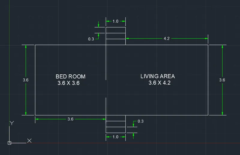
To draw the Line diagram of the two bedroom building to use the software of Auto CAD.
PROCEDURE
- To open the new sheet and type,, U’’ in command bar to change the units into meters.
- To check and proceed all dimension of the given plan.
- Type,,L’’ to give the line command and to give the dimensions to the command, the line was drawn. Indicate the direction of the line by line keeping ortho in ON.
- Type ,,O” for the offset command and type the dimensions as 0.30m, then check. Inside, where parallel line is required. For this diagram we have to use this commands in STEPS.
- Type ,, DT ‘’ for the command to mention the name of the given area of the plan.
- Type ,, DLI’’ command for to give the dimensions of each particular part, after finishing the drawing work .
- To check the proper dimension of the each and every point.
- To save the file, go to the auto cad application to choose the save option.
RESULTS
The diagram of the given LINE diagram of a two bedroom building is drawn as per dimension using Auto CAD Software.
DIAGRAM
4.AIM
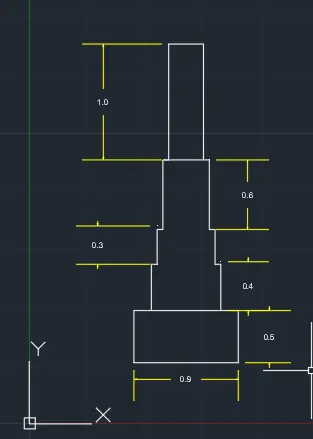
To draw the Cross- Load Bearing Wall showing Foundation details to use the software of Auto CAD.
PROCEDURE
- To open the new sheet and type,, U’’ in command bar to change the units into meters.
- Type,,L’’ to give the line command and to give the dimensions to the command, the line was drawn. Indicate the direction of the line by line keeping ortho in ON.
- Type ,, DT ‘’ for the command to mention the name of the given area of the plan.
- Type ,, DLI’’ command for to give the dimensions of each particular part, after finishing the drawing work .
- To check the decimals for the given measurement properly.
- To save the file, go to the auto cad application to choose the save option.
RESULTS
The diagram of the given Cross- Load Bearing Wall showing Foundation details is drawn as per dimension using Auto CAD Software.
DIAGRAM
5.AIM
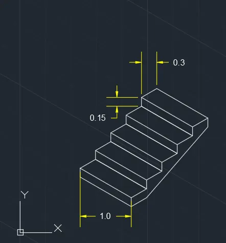
To draw the ISOMETRIC view oF Steps to use the software of Auto CAD.
PROCEDURE
- To open the new sheet and type,, U’’ in command bar to change the units into meters.
- To check the all dimension and direction about the isometric view stairs.
- Type ISOMETRIC options to change the cursher is isometric plane.
- To change the isometric plane to three options for our drawing convenient, like isoplane right, isoplane left and isoplane top.
- To check the dimension with a proper decimal, to draw it.
- Type ,, DT ‘’ for the command to mention the name of the given area of the plan.
- Type ,, DLI’’ command for to give the dimensions of each particular part, after finishing the drawing work . Here taking the angular dimensional method.
- To save the file, go to the auto cad application to choose the save option.
RESULTS
The diagram of the given ISOMETRIC view of steps is drawn as per dimension using Auto CAD Software.
DIAGRAM
6.AIM
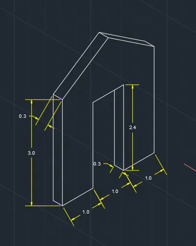
To draw the ISOMETRIC view Of GABLE WALL to use the software of Auto CAD.
PROCEDURE
- To open the new sheet and type,, U’’ in command bar to change the units into meters.
- To check the all dimension and direction about the isometric view GABLE WALL.
- Type ISOMETRIC options to change the cursher is isometric plane.
- To change the isometric plane to three options for our drawing convenient, like isoplane right, isoplane left and isoplane top.
- To check the opening area proceed the given view.
- Type ,, DT ‘’ for the command to mention the name of the given area of the isometric view.
- Type ,, DLI’’ command for to give the dimensions of each particular part, after finishing the drawing work . Here taking the angular dimensional method.
- To save the file, go to the auto cad application to choose the save option.
RESULTS
The diagram of the given ISOMETRIC view of GABLE WALL is drawn as per dimension using Auto CAD Software.
DIAGRAM
.