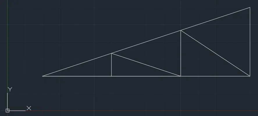
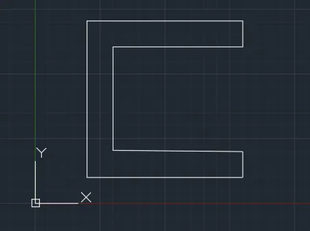
Creation of geometries by Coordinate system methods using AutoCad
1.AIM
To draw a given diagram by using the line and various commands in AutoCad.
PROCUDURE
- First to create a new sheet in auto cad and set the required format for units of measure.
- For this diagram mostly required to using a different measurement of lines can be used to draw objects.
- Select the line L tool from commands, tool bar or draw menu.
- The first point of diagram is (2,1), it is the reference point. The 2 in X direction and 1 in Y direction from origin(0,0).
- The next point is (8,1).
- The next point is (8,2).
- The next point is (3,2).
- The next point is (3,6).
- The next point is ( 8,7).
- The next point is (8,8).
- The next point is (2,8).
- Then finally, to use the close commands. TYPE – C to enter it.
- This method of dimension mentioning in cartesian coordinate method.
RESULTS
The diagram of given plan is drawn as per dimension using the software Auto CAD.
DIAGRAM
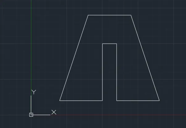
2.AIM
To draw a given diagram by using the line and various require commands in Auto CAD.
PROCEDURE
- The Line command is used to draw this diagram, before we set the all units as per required limits in new sheet.
- All measurements are mentioned in the commands bar to draw by automatically in a correct dimensions.
- To select the line commands ‘ L ‘.
- For this plan , the reference point of first point is ( 2,1). All the points are taken in a sheet from origin (0,0). If we select the next all points also taken from origin point in X and Y direction.
- The value 2 is X in direction and value 1 is Y in direction.
- This procedure is same for all next points to draw.
- And then the next point is (5,1).
- The next point is (5,5).
- The next point is (6,5).
- The next point is (6,1)).
- The next point is (9,1).
- The next point is (8,8).
- The next point is (4,8).
- Finally to choose the commands CLOSE ‘C’.
- This method of dimension mentioning in cartesian coordinate method.
RESULTS
The diagram of given plan by using various commands in Auto CAD.
DIAGRAM
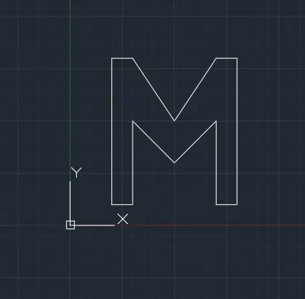
3.AIM
To draw a given diagram by using various commands in Auto CAD.
PRODCEDURE
- To select the command LINE – ‘L’.
- The first point of reference is (2,1). The value of 2 in X direction and the value of 1 in Y direction from origin point (0,0) of the sheet.
- The next point is (2,8).
- The next point is (3,8).
- The next point is (5,5).
- The next point is (7,8).
- The next point is (8,8).
- The next point is (8,1).
- The next point is (7,1).
- The next point is (5,7).
- The next point is (5,3).
- The next point is (3,5).
- The next point is (3,1).
- And then finally, to choose the command CLOSE – ‘C’.
RESULTS
The diagram of given plan by using the various commands in Auto CAD.
DIAGRAM
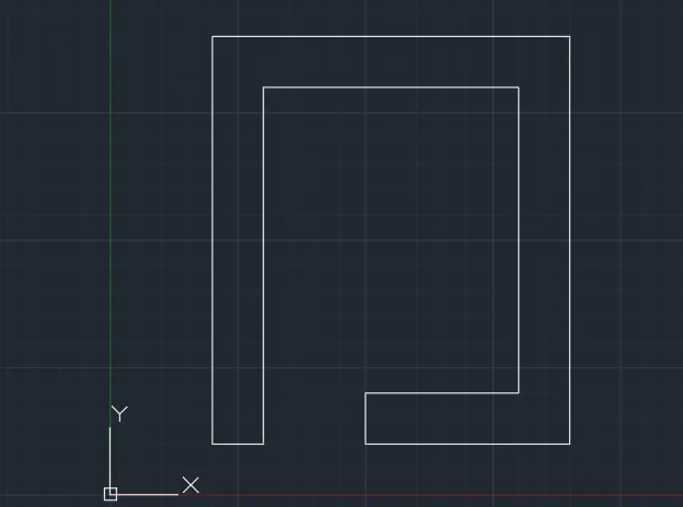
4.AIM
To draw a given diagram by using various commands in Auto CAD.
PROCUDURE
- To select the LINE – ‘L’ Tool.
- To select the first reference point is (2,1). The same procedure of the values of 2 in X direction and the value of 1 in Y direction, taken from origin point of (0,0).
- The next point is (2,9).
- The next point is (9,9).
- The next point is (9,1).
- The next point is (5,1).
- The next point is (5,2).
- The next point is (8,2).
- The next point is (8,8).
- The next point is (3,8).
- The next point is (3,1).
- Finally, to choose the command CLOSE – ‘C’ to complete the diagram.
RESULTS
The diagram of the given plan is drawn by using the various tool and commands in Auto CAD.
DIAGRAM
5.AIM
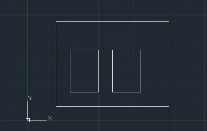
To draw the given diagram to use the various commands in Auto CAD.
PROCEDURE
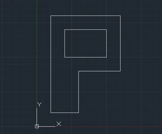
- To select the tool LINE – ‘L’.
- This diagram is under the category of relative coordinate system in rectangular plan.
- The first reference point is ( 2,1). The value of 2 in X direction and the value of 1 in Y direction, taken from the values at origin point (0,0).
- The next point is (2,7).
- The next point is (10,7).
- The next point is (10,1).
- Finally to choose the command CLOSE, to close the rectangular diagram.
- And then to draw a two interfere rectangular box in the already drawn rectangular box.
- The first interfere rectangular box, reference value is ( 3,2). The same procedure of the value of 3 is X direction and 2 in Y direction, also taken from the same origin point (0,0).
- The next point is (3,5), (5,5) and (5,2).
- Finally to select the command CLOSE, to complete the rectangular box.
- And then to start the second interfere rectangular box, the first point is ( 6,2)
- The next point is (6,5), ( 8,5) and 8,2).
- Finally to choose the command CLOSE , to finish the diagram.
RESULTS
The diagram of the given plan is drawn by using various commands in Auto CAD.
DIAGRAM
6.AIM
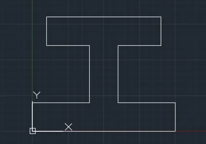
To draw the given I- section to use the various commands in Auto CAD.
PROCEDURE
- To select the Command LINE – L.
- The first reference point is (0,0). The value of 0 in X direction and the value of 0 in Y direction.
- The continuously do the next to next point with the analysis of all dimensions.
- The next point is (0,2).
- The next point is (4,2).
- The next point is (4,6).
- The next point is (1,6).
- The next point is (1,8).
- The next point is (9,8).
- The next point is (9,6).
- The next point is (6,6).
- The next point is (6,2).
- The next point is (10,2).
- The next point is (10,0).
- Finally, we have to choose the Command CLOSE-‘C’
RESULTS
The diagram of given plan of I-section is drawn by using the various commands in Auto CAD.
DIAGRAM
7.AIM
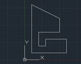
To draw the given section to use the various commands in Auto CAD.
PROCEDURE
- To Create a new sheet with particular units.
- To select the command LINE-‘L’.
- The first reference point is (1,1). The value of 1 in X direction and value of 1 in Y direction, taken from the origin point is (0,0).
- The same line command is used to draw the next to next point.
- The next point is (1,8).
- The next point is (5,6).
- The next point is (5,4).
- The next point is (2,4).
- The next point is (2,2).
- The next point is (3,2).
- The next point is (3,3).
- The next point is (6,3).
- The next point is (6,1).
- Finally to choose the command Close-‘C’ to finish the diagram.
RESULTS
The diagram of the given plan is drawn by using the various commands in Auto CAD.
DIAGRAM
8.AIM
To Draw the given plan to use the various commands in Auto CAD.
PROCEDURE
- To create a new sheet with required particular units.
- To select the command LINE-‘L’.
- To take the first reference point is (1,1). The value are taken from the origin point is (0,0).
- The next point is (1,8).
- The next point is (6,8).
- The next point is (6,4).
- The next point is (3,4).
- The next point is (3,1).
- To choose the command CLOSE – ‘C’ to finish the diagram
- And then, this section have one more rectangular box , the same procedure is taken to continuously.
- To identify the first point is (2,5), this values also taken from same origin point(0,0).
- The next point is (2,7), (5,7) and (5,5).
- Finally to select the command CLOSE-‘C’.
RESULTS
The diagram of the given plan section is drawn by using the various commands in Auto CAD.
DIAGRAM
9.AIM
To draw the given plan to use the various commands in Auto CAD.
PROCEDURE
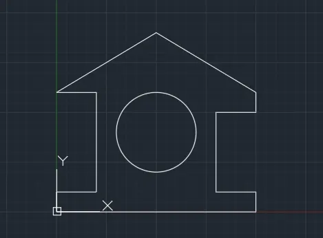
- This plan is consists of angel in a truss structure by using the polar coordinates system methods to draw the diagram.
- Before we denotes the degree value in the direction of positive X direction is 0, the positive Y direction is 90, the negative X direction is 180 and the negative Y direction is 270.
- The first reference point is (0,0), also taken from the origin values of the grid lines.
- The next point value is (@1<90).
- The next point value is (@2<0).
- The next point value is (@5<90).
- The next point value is (@2<180).
- The next point values is choose the distance of one side truss value with the given angle.
- To type the command bar id (@5.831<30.964).
- The next point value is (@5.831<329.036).
- The next point value is (@1<270).
- The next point value is (@2<180).
- The next point value is (@4<270).
- The next point value is (@2<0).
- The next point value is (@1<270).
- Finally to choose the command in CLOSE- ‘C’.
- And then to draw the circle in the truss by using the circle command.
- To choose the draw tool in circle command, CIRCLE AND RADIUS options.
- The values of the center of the circle is (5,4) and then to summit the value of radius is 2.
RESULTS
The diagram of the given plan is drawn by using the various commands like line, circle, etc.., in Auto CAD.
DIAGRAM
10.AIM
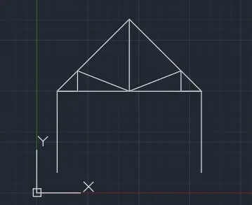
To draw the given plan of Queen post truss to use the required commands in Auto CAD.
PROCEDURE
- To select the command in LINE, to draw the line in given dimensions.
- The first reference point is (1,1), also taken the values from the origin point (0,0) in both the direction.
- The next point value is (@4<90).
- The next point value is (@5<45).
- The next point value is (@5<315).
- The next point value is (@4<270), close the sketch
- And then to start the next reference point is ( 2,5).
- The next point value is (@1<90).
- To draw the intermediate line between top to middle portion of the truss and to join the truss intermediate point.
RESULTS
The diagram of the given queen post truss by using the various commands in Auto CAD.
DIAGRAM
11.AIM
To draw the plan of steel truss to use the various commands in Auto CAD.
PROCEDURE
- To select the line command , to draw the line.
- To draw the first reference point p1 is (1,1) and the next point p2 is (@6<0)
- The next point p3 is (@2<90).
- Then, to joint the point value is p1 and p3 to form the triangle shape of truss.
- The next reference point is ( @2<0) from the values taken from point p1.
- Then to given the dimension of intermediate dimensions is ( @0.667<90).
- The same procedure to connect the next intermediate support, to given the dimension is (@4<90), then to next point is (@1.333<90), finally to connect the point P2.
RESULTS
The diagram of the given truss is drawn by using the software in Auto CAD.
DIAGRAM