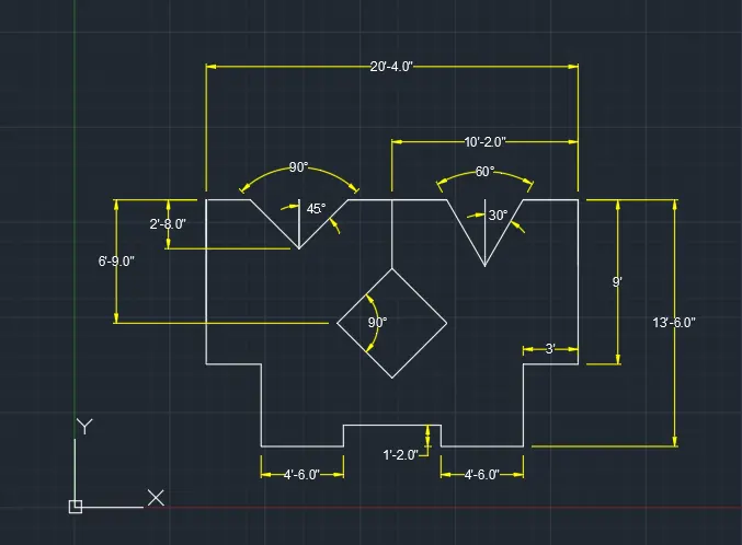
Drafting of various geometries using Chamfer, Fillet tool in AutoCad
1.AIM
To draw the given plan using the various commands in Auto CAD.
PROCEDURE
- To open the new sheet from application manager.
- TYPE ..U ‘ in command bar(enter) and to set up the units in meters with the proper decimal.
- To observation the diagram, to select required commands.
- TYPE ,, L’ in command bar to start the line to draw for the given dimension and indicate the direction of lines, if Ortho is ON.
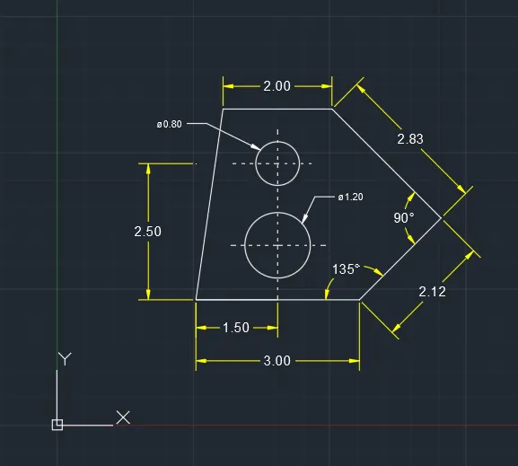
- To draw the line , if we need to inclined dimension with a degree to study the accurate measurement of angle by the analysis of direction of sides. For ex ( @2.83<315).
- By Typing ,,C’ to draw the circle with a proper center point and to select the center point then to enter the dimension of diameter.
- TYPE ,,DLI’ in command bar to give the dimension of the plan.
- TYPE ,,D’ in command bar to give the size of the dimension and size of the arrows, changing tool command is DDIM.
- After completing the diagram to save it.
RESULTS
The diagram of the given plan is drawn by using the software of Auto CAD.
DIAGRAM
2.AIM
To draw the given plan using the various commands in Auto CAD.
PROCEDURE
- To open the new sheet from application manager
- TYPE ..U ‘ in command bar(enter) and to set up the units in FEET and INCHES with the proper decimal.
- To observation the diagram, to select required commands.
- TYPE ,, L’ in command bar to start the line to draw for the given dimension and indicate the direction of lines, if Ortho is
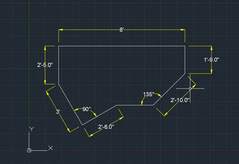
- To draw the line , if we need to inclined dimension with a degree to study the accurate measurement of angle by the analysis of direction of sides. For ex ( @2’10”<225).
- HERE, we need to find the third side angle and dimension by the mathematical way and to draw the line by using the finding angle.
- For example … (@3’0” <300).
- TYPE ,,D’ in command bar to give the size of the dimension and size of the arrows, changing tool command is DDIM.
- After completing the diagram to save it.
RESULTS
The diagram of the given plan is drawn by using the software of Auto CAD.
DIAGRAM
3.AIM
To draw the given plan using the various commands in Auto CAD.
PROCEDURE
- To open the new sheet from application manager
- TYPE ..U ‘ in command bar(enter) and to set up the units in FEET and INCHES with the proper decimal.
- To observation the diagram, to select required commands.
- TYPE ,, L’ in command bar to start the line to draw for the given dimension and indicate the direction of lines, if Ortho is
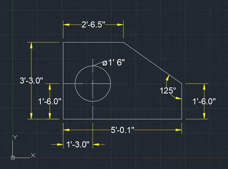
- To draw the line , if we need to inclined dimension with a degree to study the accurate measurement of angle by the analysis of direction of sides. For ex ( @1’6.0” <135).
- TYPE,, CLOSE’ to finish and close the particular part.
- Next , to draw the circle.
- Before we select the center point of the circle, to fix the base point then to take the 1’3.0” from X axis and 1’6.0” in Y axis.
- TYPE ,,C’ To draw the circle at a given diameter.
- TYPE ,,DLI’ in command bar to give the dimension of the plan.
- TYPE ,,D’ in command bar to give the size of the dimension and size of the arrows, changing tool command is DDIM.
- After completing the diagram to save it.
RESULTS
The diagram of the given plan is drawn as per dimension using the software of Auto CAD.
DIAGRAM
4.AIM
To draw the given plan using the various commands in Auto CAD.
PROCEDURE
- To open the new sheet from application manager
- TYPE ..U ‘ in command bar(enter) and to set up the units in METERS with the proper decimal.
- TYPE ,, L’ in command bar to start the line to draw for the given dimension and indicate the direction of lines, if Ortho is
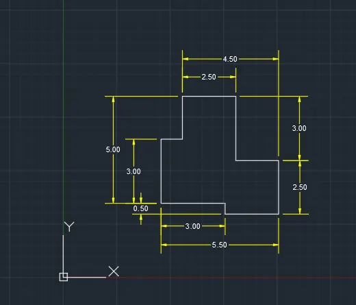
- For this diagram , we have to find the every side dimensions accurately and ploy properly, then only to complete the diagram perfectly.
- To check side by side measurement.
- TYPE ,,DLI’ in command bar to give the dimension of the plan.
- TYPE ,,D’ in command bar to give the size of the dimension and size of the arrows, changing tool command is DDIM.
- After completing the diagram to save it.
RESULTS
The diagram of the given plan is drawn as per dimension using the software of Auto CAD.
DIAGRAM
5.AIM
To draw the given plan using the various commands in Auto CAD.
PROCEDURE
- To open the new sheet from application manager
- TYPE ..U ‘ in command bar(enter) and to set up the units in METERS with the proper decimal.
- TYPE ,, L’ in command bar to start the line to draw for the given dimension and indicate the direction of lines, if Ortho is
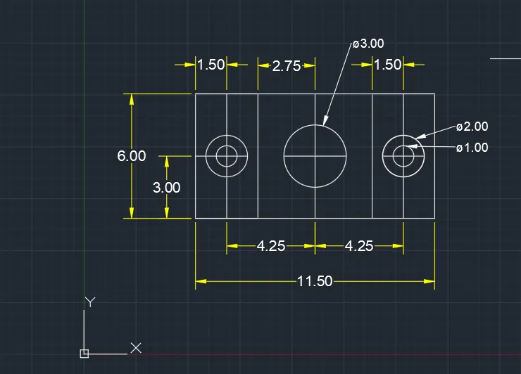
- For this diagram, used to mirror options for the given measurement.
- We have selected the one half of side , to draw the accurate measurement.
- Next , to draw the circle.
- Before we select the center point of the circle, to fix the base point then to take the 1.50m from X axis and 3.0m in Y axis.
- TYPE ,,C’ To draw the circle at a given diameter.
- The given diameter of the circle is ( 2m and 1m) in same center point and the next circle dia is 3m.
- And to Type,, MIRROR’ to select the half side of the object (enter), to mirror the other side of full diagram.
- TYPE ,,DLI’ in command bar to give the dimension of the plan.
- TYPE ,,D’ in command bar to give the size of the dimension and size of the arrows, changing tool command is DDIM.
- After completing the diagram to save it.
RESULTS
The diagram of the given plan is drawn as per dimension using the software of Auto CAD.
DIAGRAM
6.AIM
To draw the given plan Of front , side and top view of the section using the various commands in Auto CAD.
PROCEDURE
- To open the new sheet from application manager
- TYPE ..U ‘ in command bar(enter) and to set up the units in METERS with the proper decimal.
- TYPE ,, L’ in command bar to start the line to draw for the given dimension and indicate the direction of lines, if Ortho is
- Type,,O’ in command bar, to select the offset option and type offset distance ten click inside where the parallel lines is required.
- TYPE ,,DLI’ in command bar to give the dimension of the plan.
- TYPE ,,D’ in command bar to give the size of the dimension and size of the arrows, changing tool command is DDIM.
- After completing the diagram to save it.
RESULTS
The diagram of the given plan of front , side and top view of the section is drawn as per dimension using the various commands in Auto CAD.
DIAGRAM

7.AIM
To draw the given plan using the various commands in Auto CAD.
PROCEDURE
- To open the new sheet from application manager
- TYPE ..U ‘ in command bar(enter) and to set up the units in CENTIMETERS with the proper decimal.
- TYPE ,, L’ in command bar to start the line to draw for the given dimension and indicate the direction of lines, if Ortho is
- Type,,O’ in command bar, to select the offset option and type offset distance ten click inside where the parallel lines is required.
- Type,, Tr’ for trim command , to trim the extra lines after the dimensions.
- TYPE ,,C’ To draw the circle at a given diameter.
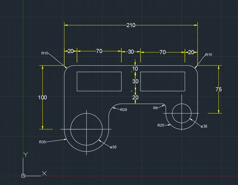
- The given diameter of the circle is ( 50 and 30m) before we fix the center point of the given dimensions.
- Type ,,A’ in command bar, to draw the Arc for given dimension of radius.
- Type ,,REC’ to draw the rectangle using the rectangle command with length and width dimensions.
- TYPE ,,DLI’ in command bar to give the dimension of the plan.
- TYPE ,,D’ in command bar to give the size of the dimension and size of the arrows, changing tool command is DDIM.
- After completing the diagram to save it.
RESULTS
The diagram of the given plan is drawn as per dimension using the software of Auto CAD.
DIAGRAM
8.AIM
To draw the given plan using the various commands in Auto CAD.
PROCEDURE
- To open the new sheet from application manager
- TYPE ..U ‘ in command bar(enter) and to set up the units in CENTIMETERS with the proper decimal.
- TYPE ,, L’ in command bar to start the line to draw for the given dimension and indicate the direction of lines, if Ortho is
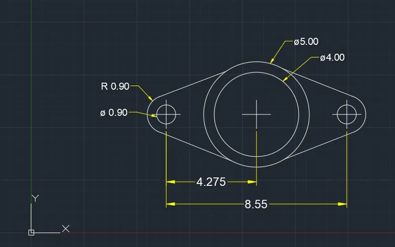
- HERE, we fixed the centroid of the three circle and then to draw the circle.
- TYPE ,,C’ To draw the circle at a given diameter.
- Type ,,A’ in command bar, to draw the Arc for given dimension of radius.
- Type ,,DDPTYPE’ to draw and fix the icon of the centroid.
- The given diameter of the holes of 5cm, 4cm and 0.90cm
- Type,, Tr’ for trim command , to trim the extra lines after the dimensions.
- TYPE ,,DLI’ in command bar to give the dimension of the plan.
- TYPE ,,D’ in command bar to give the size of the dimension and size of the arrows, changing tool command is DDIM.
- After completing the diagram to save it.
RESULTS
The diagram of the given plan is drawn as per dimension using the software of Auto CAD.
DIAGRAM
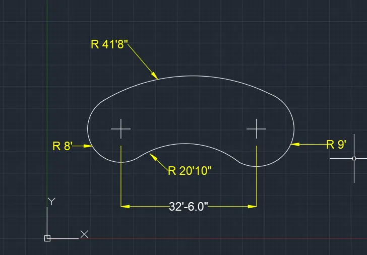
9.AIM
To draw the given plan using the various commands in Auto CAD.
PROCEDURE
- To open the new sheet from application manager
- TYPE ..U ‘ in command bar(enter) and to set up the units in FEET AND INCHES with the proper decimal.
- Both the two sides are draw the circle with a proper centroid of the given measurement.
- Then to connect the Arc for given radius of the dimension, its connected.
- TYPE ,,C’ To draw the circle at a given diameter.
- The given radius of the circle is ( 8 feet and 9 feet).
- The given Arc radius dimension is ( 41’8” and 20’10”).
- The center to center distance between the two centroidal point is (32’ 6”).
- Type,, Tr’ for trim command , to trim the extra lines after the dimensions.
- Trimmed the extra dimensions of the circle , surrounding the ARC.
- TYPE ,,DLI’ in command bar to give the dimension of the plan.
- TYPE ,,D’ in command bar to give the size of the dimension and size of the arrows, changing tool command is DDIM.
- Here we choose the more options of angular dimension and leader dimemsions
- After completing the diagram to save it.
RESULTS
The diagram of the given plan is drawn as per dimension using the software of Auto CAD.
DIAGRAM
10.AIM
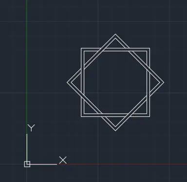
To draw the given SECTION using the various commands in Auto CAD.
PROCEDURE
- To open the new sheet from application manager
- TYPE ..U ‘ in command bar(enter) and to set up the units in METERS with the proper decimal.
- To draw Square with the dimensions of 1m at both sides,
- Then, Type,,O’ in command bar, to select the offset option and type offset distance ten click inside where the parallel lines is required.
- Take the offset distance of 0.1m.
- To take command ,, COPY’ For moves the objects from a drawn square, to paste the requires place for the same objects of one more.
- Type command ,, ROTATE’ to select the object and to given the rotating angle at 45 degree.
- Then , to choose ,, MOVE ‘ option to move the object to the before drawn square center.
- Type,, Tr’ for trim command , to trim the extra lines after the dimensions.
- After completing the diagram to save it.
RESULTS
The diagram of the given plan is drawn as per dimension using the software of Auto CAD.
DIAGRAM
11.AIM
To draw the given plan using the various commands in Auto CAD.
PROCEDURE
- To open the new sheet from application manager
- TYPE ..U ‘ in command bar(enter) and to set up the units in FEET and INCHES with the proper decimal.
- TYPE ,, L’ in command bar to start the line to draw for the given dimension and indicate the direction of lines, if Ortho is To draw the line , if we need to inclined dimension with a degree to study the accurate measurement of angle by the analysis of direction of sides. For ex .(@2’8”<135).
- HERE, we need to find the third side angle and dimension by the mathematical way and to draw the line by using the finding angle.
- Type,, MIRROR’ to select the half side of the object (enter), to mirror the other side of full diagram.
- Type,, Tr’ for trim command , to trim the extra lines after the dimensions.
- Trimmed the extra dimensions of the circle , surrounding the ARC.
- TYPE ,,DLI’ in command bar to give the dimension of the plan.
- TYPE ,,D’ in command bar to give the size of the dimension and size of the arrows, changing tool command is DDIM.
- Here we choose the more options of angular dimension
- After completing the diagram to save it.
RESULTS
The diagram of the given plan is drawn as per dimension using the software of Auto CAD.
DIAGRAM