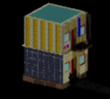
Creating a 3D rendered model for a Residential Building in AutoCad
AIM TO CREATE A 3 D MODEL OF THE RSIDENTAL BUILDING WITH A RENDED VIEW
procedure
1 open autocad
2 open a new sheet in metric system
3 set the units
4 set the limts frim 0,0
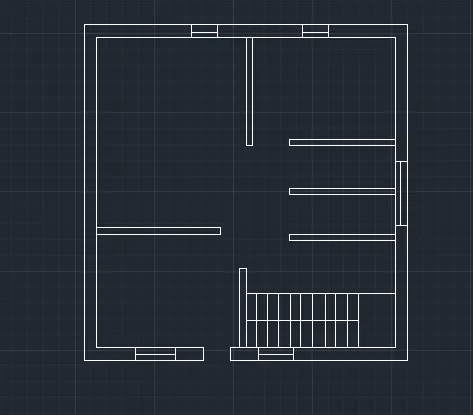
5 now take the rec option and draw a rec of 10,10
6 now giveit a offset of 0.5to make exxternall wall thickness
7 now use the offset command to draw a intrnel wall of 6 from the top externel wall nd now give it a offset of 0.2 to make the internel wall thickness
8 now grom the ytop wall give a offset at 3.5 ,4.5 ,6.5 to make kitchen and bathroom
9 now give this walls a offset of 0.2 to make internwel wll thickness
10 use the offset command and give a offset of 4 from the right wall at b = 4 to make the steps partichion give it a offt of 0.2 tio make internel wall thicknes
11 now use the trim command to remmove the unwanted line
12 now use the trim command and snap option to make doors were it i reqiuired
13 use the trim command and the line commaand and turn on the mid point in the snap settings to draw the windows
14 use the copy command to copy the window and place it were it is required
15 now draw the steps with the help of line command draw a straight line and give a offset of 0.4 to create the number of steps
16 dimentions bedroom = 5,6
bedroom 2 = 4.5,3.5
kitchen = 3.,1.5
bathroom = 3.1,1.5
parking = 4,3.5
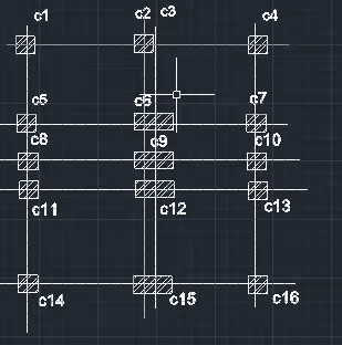
17 now draw the draw lines over the plan to draw the beam and coulumbs plan
18 move the grid lines to a new location
19 take a small square of 0.2,0.2 to mark the intersection of the grid lines to install the pilllers
20 use the hatch command to hatch the small square and hatch it by selecting the pattern of the hatch
21 now use the m text command nd set the height of the text to0.4 and rotation angle is 0 andwrite the coloubs names
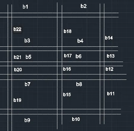
22to make a beam plan copy the coloumb plan and give a offset of 0.4 to the grid lines which are connecting the coloumbs
23 now use the m text command to write the name if the beams
24 set the heightof the text to 0.4 and rotation angle to 0
25 mark the beams
26 now to draw the section view dtaw the x and y line over any section of the lan
27 now draw the parts which are visible from the intersection part of the lines
28 the visible points are the thr door windows and the wlls
29 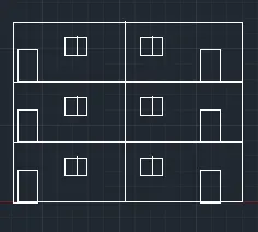
30 now to make the elevation draw a rec of 10,10
31 now to draw a door at the center of the rec
32 give a offset of 0.2 to make the door frame
33 now use the rec and the line command to make the window
34 draw a rec of 2.2,2.2 and give a offset of 0.2 to make the window holder
35 now draw a line in the center to make the windows
36 now copy the door and windows to tje upper floor of the diagram with the help of copy and move command
37 now use the offset and line coomand to make the balconey grill design
38 use the rec command to make two rec of diffrent sizes to make the detaling on the elevation
39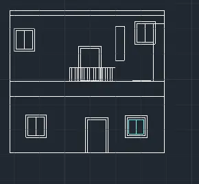
40 now to convert the plan into d go to the setiing and go to the d modeling design center
41 now select the wallls and give a boundry command and select the couour of the layer and make the layer current of the plan and click on the exrude option
42 give the h = 10
43 now draw a rec by placing the ucs at the wall you are working on and draw a rec and do the exxtrude commaand
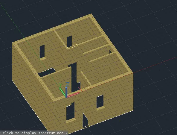
44 do the extution till 5 to the level of the door
45 go this procedure to make the correct spaing to fit the doors and windows
46 now take the elevation plan and make it 3d rotate to make it stand in 90 digrees
47 now move the elevation in frount of the plan
48 now make a copy of the elevation and move it to nother location
49 now ungroup the elevaation and take the doors and windows
50 now go to the layer option and create the different ayers such as 3d wall externall 3 d wall internall , flooring , slab , door hoder , window glass ,window holder
51 now place the doors and windos at the the places and exrude it fit perfectly
52 now copy the below portion on top of it with doors and windows
51 now select the window and do the boundry command select the coundry and select the layer you are working on and press the excrude option
52 now select the window holder option layer and give it acolour and then excure it
53 give ita value
54 sub the window frm the window holder
55 window holder frame will be eready
56 to sub select the bigger part cick enter then click on the smaler object and fclick enter
57 now make a door by giving the boundury command on the rec and select excrude
58 now select the outer layer of thedooor and givea region command to make the door holder
59 fit the door and window at the locaton and excrude it a litle bit to make it fit perfectly
60 now copy the lower portion on the top with doors and windows
61 now go to the layer option and make the 3d layer off
62 now make a new layer called flooring and then make the rec inner part of the plan and excrude it
63 give it a value of -0.5
64 now turn the 3 d wall layer on
65 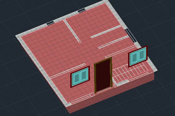
66 now with the help of ucs set it on the wall u are woorking on and then juse the rec command and the excrude command to hide the flooring
67 now draw a rec on the top portion of the plan with inner points and give it a layer called slab and give ita colour then excure it to make the terrace sab of the plan
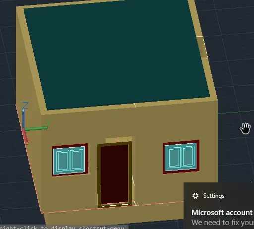
68 now turn thelyer of 3 d wall off and make a rec to make the extra extention same as the plan measurment
69 after making a rec and excrudeit to some height place it on the top of the building
70 now make steps the height of the door is 0.15 from the ground level now make 3 rec and select the steps layer and make 3 rec and excrude it t a height of 5 ,10,15 respectivly
71 now join the steps to the building
70 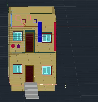
71 now with the help of the cyliner make the railing of the balocony and the steps
72 now go to the visualize option and set a camera at a distance so that the building is visible in the camera view
73 set the distance
74 set the lence of the camera
75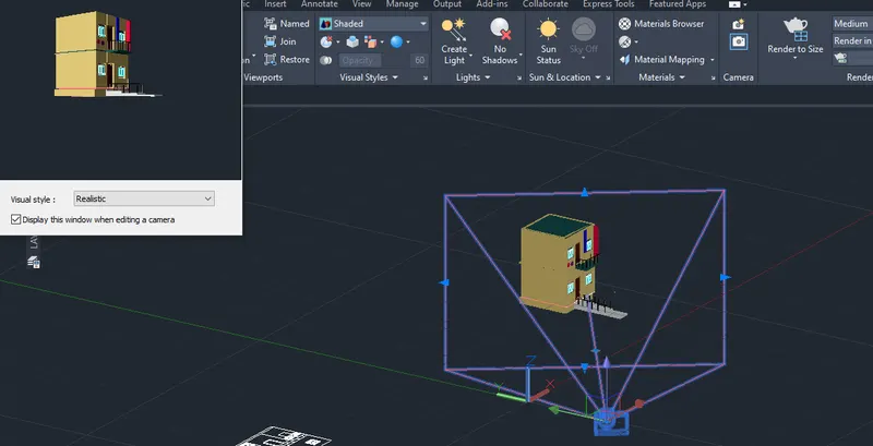
76 now go to the viualization tab and go to the material brouser
77 select the materials want to use and sent it to the upper tab
78 now give the materials to diffrent elemets
79 after giving the metreials go to visualize tab and select the render option
80 select the use without image library and select ok
81 the rendered view will pper on the screen
result the renderd view of a 3 d building