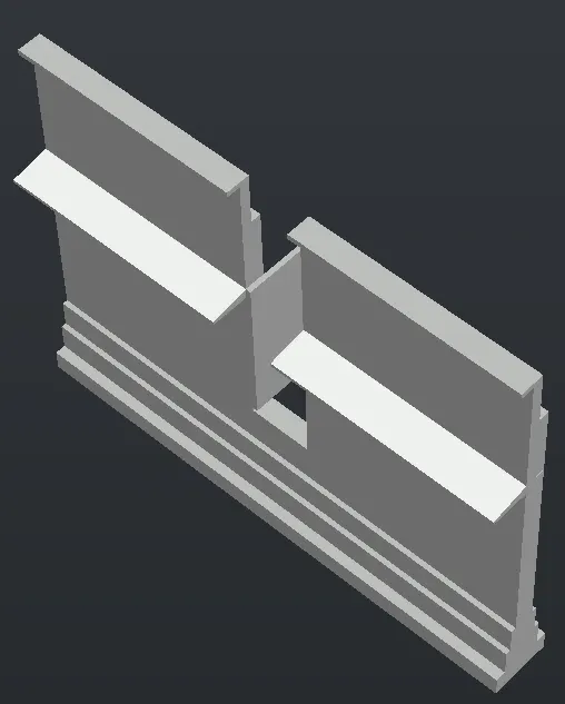
Creating 3D Isometric view of various structural elements in AutoCAD
1)
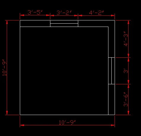
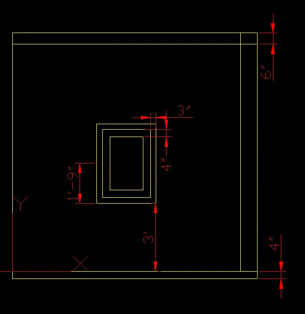
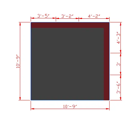
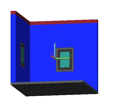
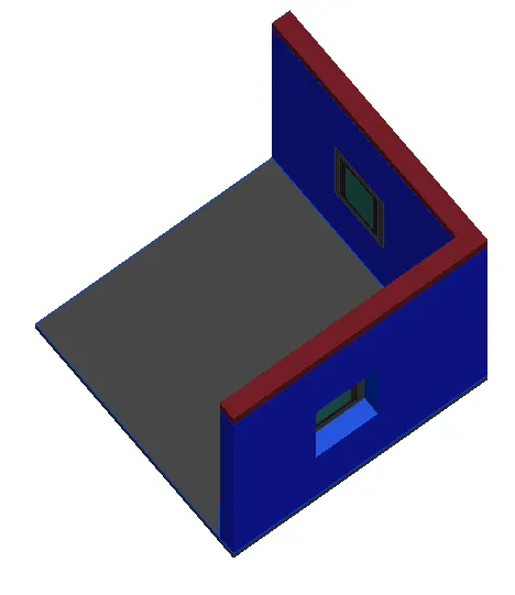
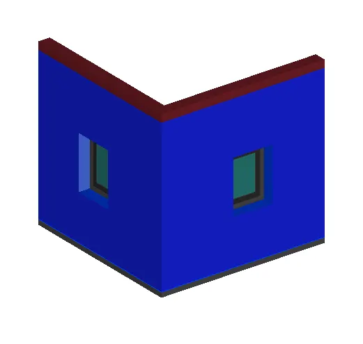
AIM-Create a 3D Isometric View of the building with plan and elevation given
PROCEDURE
- select 3d modeling from the settings
- create the 2d figure as per the given dimension
- use join command or union command to create 2d polygen
- create 3d solid fig of 2d polygen using region command
- use extrude and give the heght as per given dimension
- do the dimensioning and detailing
RESULT
2)
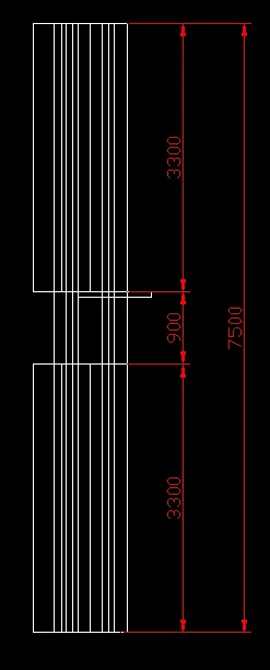
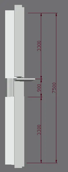
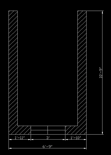
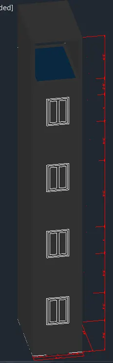
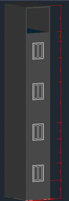
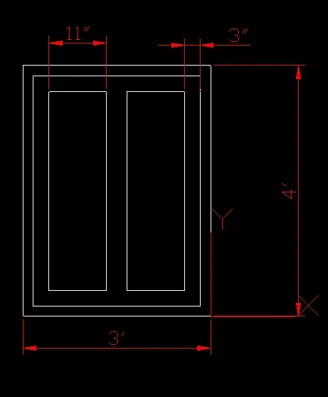
AIM-Create the 3D View of the Building Façade as given in the plan and elevation.
PROCEDURE
- select 3d modeling from the settings
- create the 2d figure as per the given dimension
- use join command or union command to create 2d polygen
- create 3d solid fig of 2d polygen using region command
- use extrude and give the heght as per given dimension
- do the dimensioning and detailing
RESULT
3)
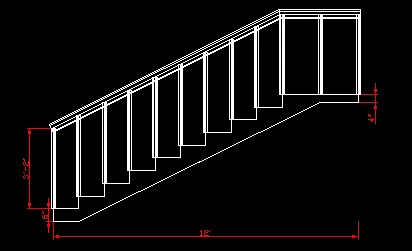
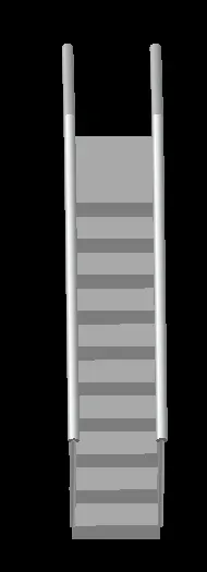
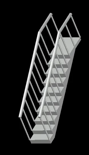
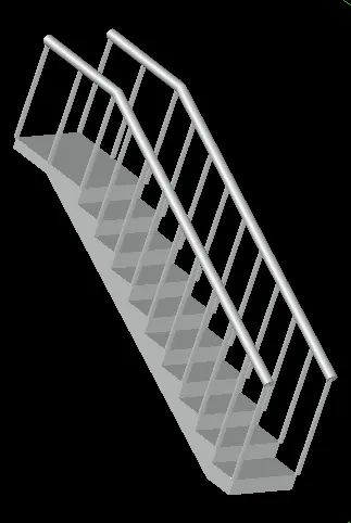
AIM-Create the ismoteric 3d view of a stair with railing as shown in the plan and elevation. Assume the size of the balustrades and the hand rails.
PROCEDURE
- select 3d modeling from the settings
- create the 2d figure as per the given dimension
- use join command or union command to create 2d polygen
- create 3d solid fig of 2d polygen using region command
- use extrude and give the heght as per given dimension
- do the dimensioning and detailing
RESULT
4)
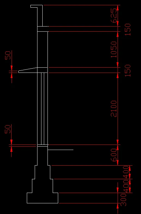
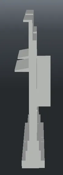
AIM-Create the 3D view of a Wall with spread footing . Create the Door opening only. Assume the size of the parpaet and the coping
PROCEDURE
- select 3d modeling from the settings
- create the 2d figure as per the given dimension
- use join command or union command to create 2d polygen
- create 3d solid fig of 2d polygen using region command
- use extrude and give the heght as per given dimension
- do the dimensioning and detailing
RESULT