Creating 3D Isometric view of various structural elements in AutoCAD
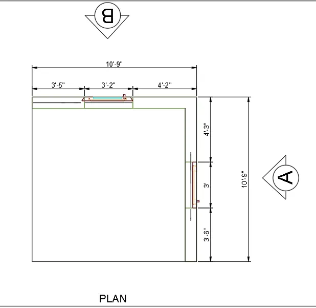
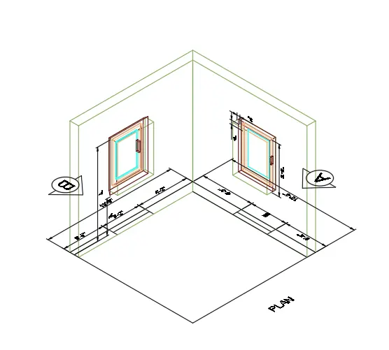
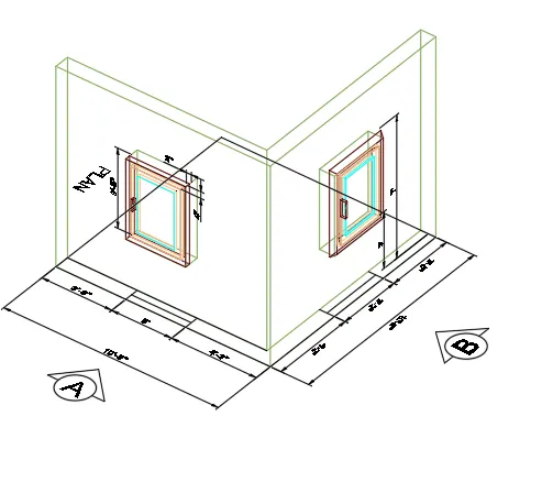
Q1. Create a 3D Isometric View of the building with plan and elevation given.
AIM:
To create a 3D isometric view of the building with plan and elevation given using Autocad 3D
PROCEDURE:
STEP 1:
- In command prompt type UNITS, set to ARCHITECTURAL, precision = 0'-0", insertion scale = INCHES
- In command prompt type LIMAX and LIMITS set to desired
- In command prompt type ZOOM, All and enter
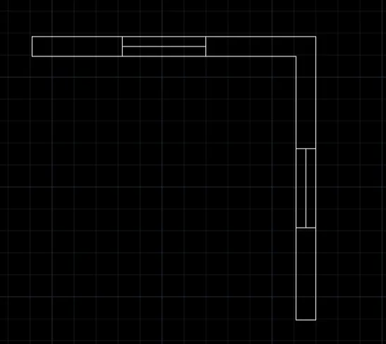
STEP 2: Drawing the plan in Top view
- In command prompt type LINE, draw the lines of distance 10'-9", 10'-9" to get L-shape
- In command prompt type OFFSET, offset the l-shape with a thickness of 9"
- In command prompt type TRIM, trim the extra lines
- In command prompt type OFFSET, offset the lines from the edges to get window and offset of 4.5" done for middle line in window
STEP 3: Plan to 3d model
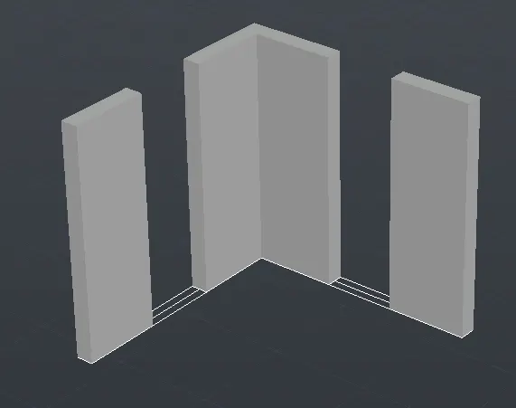
- Go to 3d view
- In command prompt type BO, create the region for the wall
- In command prompt type EXTRUDE, extrude the wall by 10'
STEP 4: Creating an opening for windows
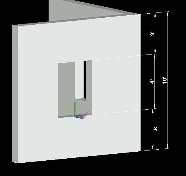
- By using UCS and REC command rectangle is created for window at bottom
- In command prompt type EXTRUDE, extrude the created rectangle by 3' on both walls to upward
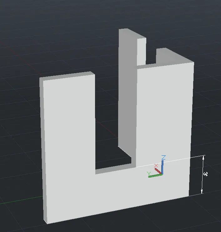
- By using UCS and REC command rectangle is created for the window at the top
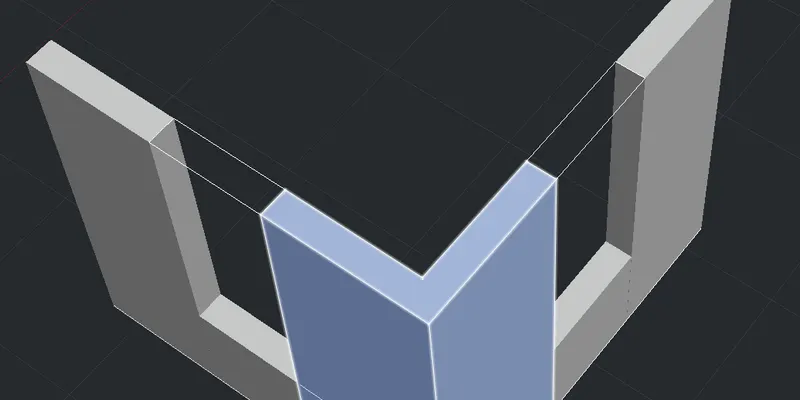
- In command prompt type EXTRUDE, extrude the created rectangle by 3' on both walls to downward
- In command prompt type UNION, select all the walls and union
STEP 5: Creation of layers and window frame
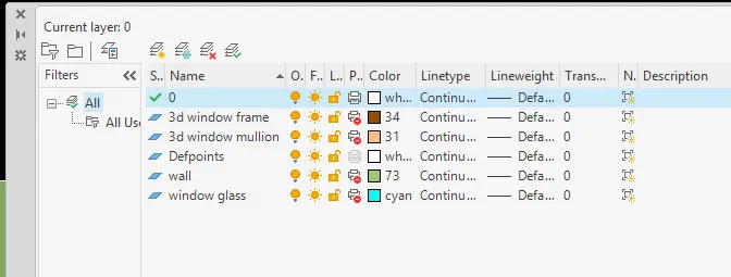
- In command prompt type LA, assign the layers with name, color, and other details if required to the created solid
- In command prompt type PLINE, in front view draw the boundary lines of the wall and window
- In command prompt type COPY, copy the created pline for the window creation
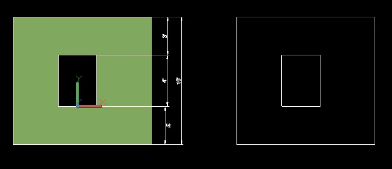
- By using EXTRUDE, SUBTRACT, BO commands window is created
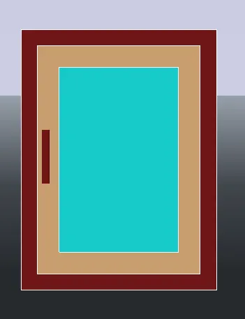
- In command prompt type MOVE, move the created window into the wall with the help of object snap do on both walls
- In command prompt type DIML, assign the dimensions
- In command prompt type DT, assign the text
ISOMETRIC VIEW
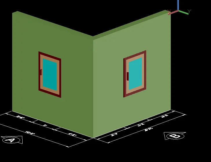
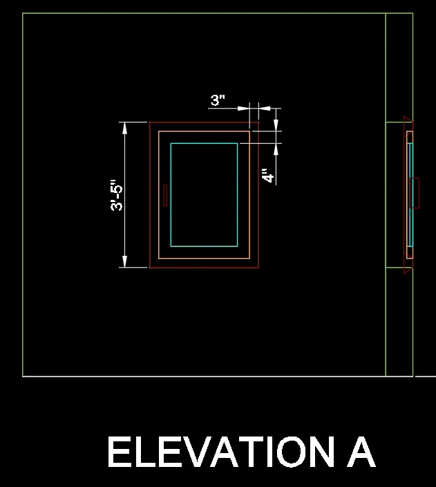
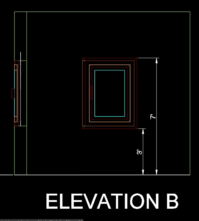
ELEVATION A ELEVATION B
RESULT:
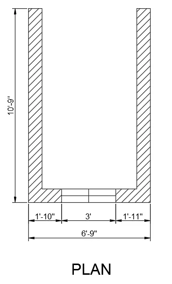
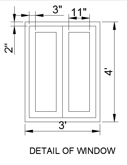
Q2. Create the 3D View of the Building Façade as given in the plan and elevation. Also, see the detail of the window.
AIM:
To create a 3D view of the building Facade as given in the plan and elevation with the help of detail of the window
PROCEDURE:
STEP 1:
- In command prompt type UNITS, set to ARCHITECTURAL, precision = 0'-0", insertion scale = INCHES
- In command prompt type LIMAX and LIMITS set to desired
- In command prompt type ZOOM, All and enter
STEP 2: Drawing of the plan in TOP view
- In command prompt type LINE, draw the lines of distance 10'-9", 6'-9", 1'-11", 3' and 1'-11" to get outer boundary
- In command prompt type OFFSET, offset the lines inward by 9" to get wall thickness
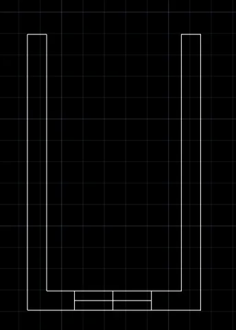
- In command prompt type HATCH, to hatch the inner region
- In command prompt type DIML, dimensions are assigned
- In command prompt type DT, assign the text
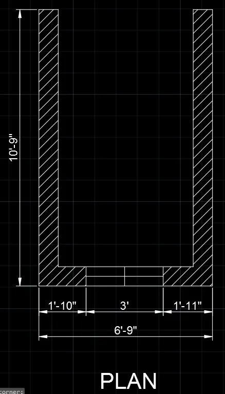
STEP 3: Creation of 3D model from plan
- change view from top to isometric view
- In command prompt type BO, select the region to form boundary
- In command prompt type EXTRUDE, extrude the selected boundary region by 10'-9" in upward direction
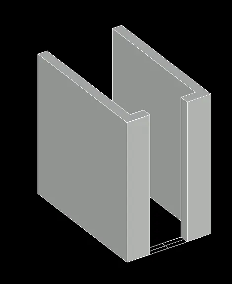
- In command prompt type LA, assign the layers with name, color, and other details if required to the extruded solid
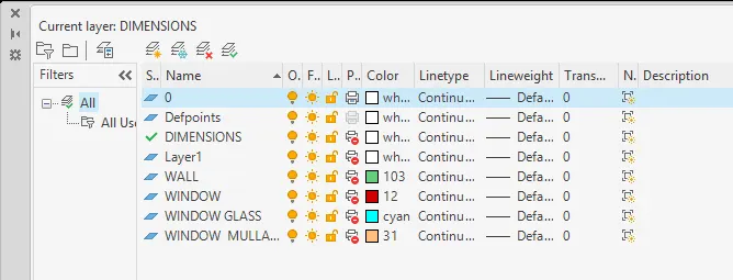
STEP 4: Creation of window
- In command prompt type UCS, select the required ucs for a better view
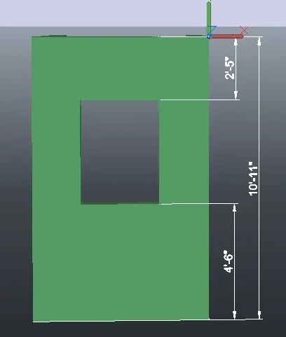
- In command prompt type REC, assign the polyline rectangle in void space left for window
- In command prompt type EXTRUDE, extrude the created rectangle in the upward direction by 4'-6"
- In command prompt type REC, assign rectangle polyline in the top void
- In command prompt type EXTRUDE, extrude the top created rectangle in the downward direction by 2'-5"
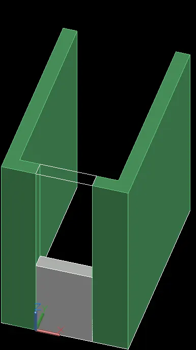
- In command prompt type UNION, select the created solids and union them
- In command prompt type DIML, assign the dimensions to the created solid wall
STEP 5: Creation of window
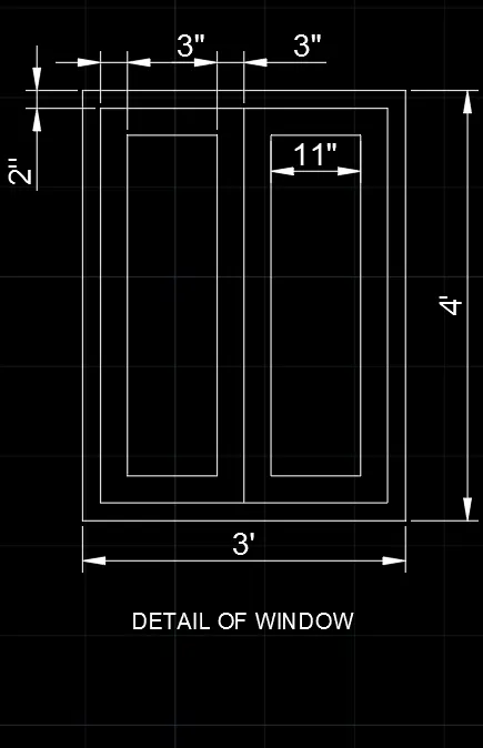
- In command prompt type REC, create the rectangle by assigning dimensions of length, width as 3',4'
- In command prompt type OFFSET, offset the created rectangle by 2" inwardly
- In command prompt type LINE, with the help of snap object from the left bottom corner of the new rectangle to 1'-4" and create the mid line
- In command prompt type OFFSET, offset the lines by 3" inwardly
- In command prompt type TRIM, trim the unwanted lines
- In command prompt type DIML, assign the dimensions
- In command prompt type DT, assign the text
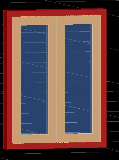
- In command prompt type BO, select the region of the created window plan
- By using SUBTRACT, EXTRUDE, RMAT commands window from plan to 3D is created
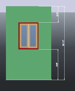
- In command prompt type MOVE, by selecting the corner of the window move to the void in wall by snap object
- In command prompt type GROUP, select all the elements and group them
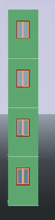
step 6: Creation multi-storey
- In command prompt type COPY, by selecting the bottom corner by snap object and placing over the top corner and done this for three times
- In command prompt type UCS, by placing ucs for the best view
- In command prompt type REC, create rec of dimension length, width as 4",9" at two corners at the top
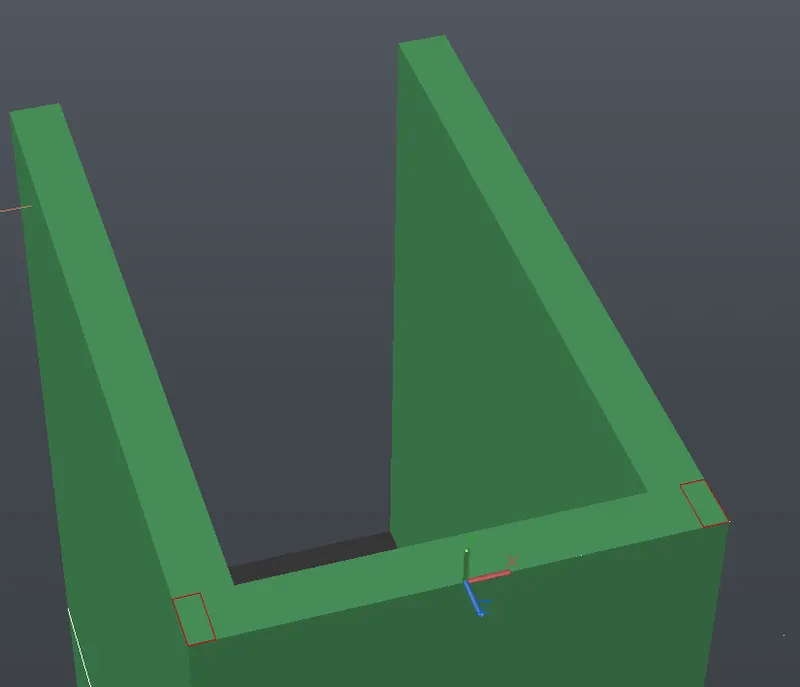
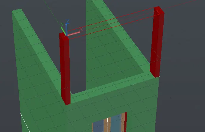
- In command prompt type EXTRUDE, extrude the created rectangles to 5'-5"
- In command prompt type UCS, for better view
- In command prompt type REC, create the rectangle by selecting the corners of newly created rectangles
- In command prompt type EXTRUDE, extrude the previous rectangle by 4" downword
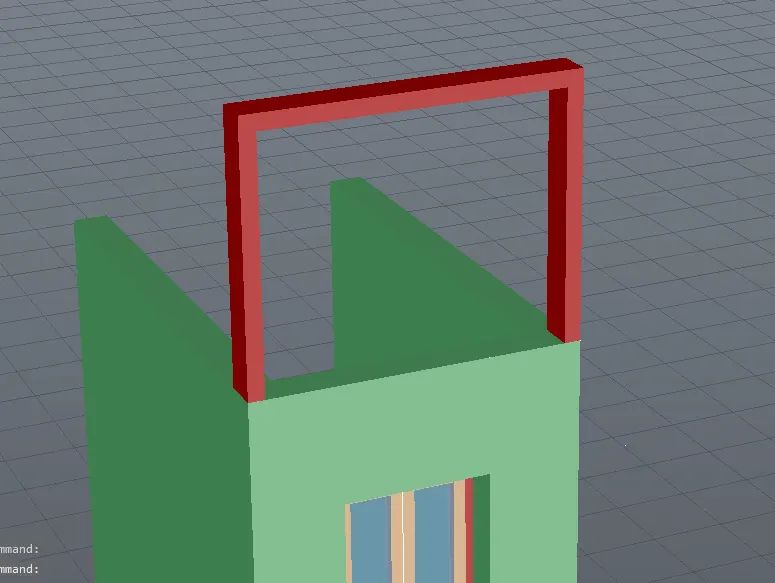
- In command prompt type DIML, assign the dimension to the created facade
- In command prompt type DT, assign the text
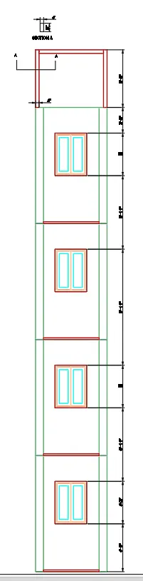
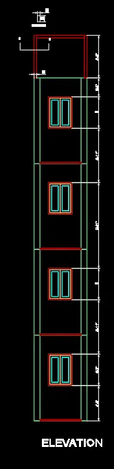
RESULT:
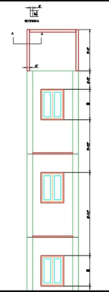
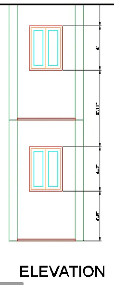
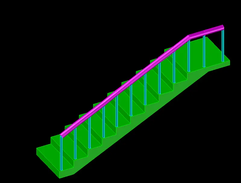
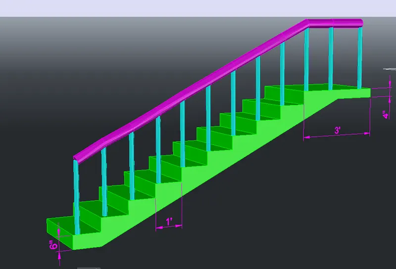
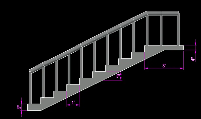
Q3. Create the ismoteric 3d view of a stair with railing as shown in the plan and elevation. Assume the size of the balustrades and the hand rails.
AIM:
To create the isometric 3D view of a stair with railing as shown in the plan and elevation using Autocad 3D
PROCEDURE:
STEP 1:
- In command prompt type UNITS, set to ARCHITECTURAL, precision = 0'-0", insertion scale = INCHES
- In command prompt type LIMAX and LIMITS set to desired
- In command prompt type ZOOM, All and enter
STEP 2: Drawing the plan in TOP view
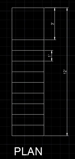
- In command prompt type REC, create a rectangle of dimensions of length, width as 3',12'
- In command prompt type EXPLODE, explode the created rectangle
- In command prompt type OFFSET, offset the explode line as 1' of nine times
- In command prompt type DIML, assign the dimension
- In command prompt type DT, assign the text to the plan
STEP 2: Side elevation and creation of 3D MODEL of it
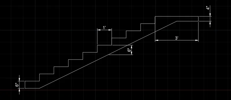
- In front view create the side elevation
- In command prompt type LINE, draw the lines as thread 1', raiser 6", waist slab 6" and landing of 3'
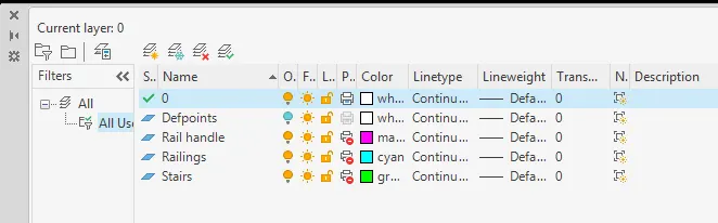
- In command prompt type LA, assign the layers with name, color, and other details if required to the extruded solid
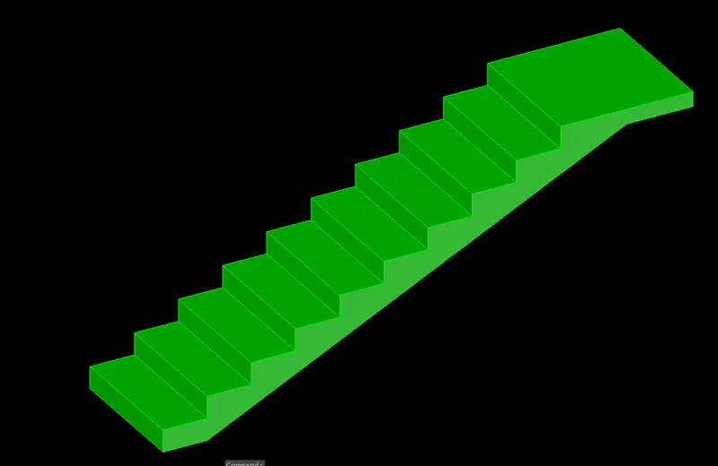
- In command prompt type BO, select the region
- In command prompt type EXTRUDE, extrude the selected region by 3'
STEP 3: Railing and railing rod creation
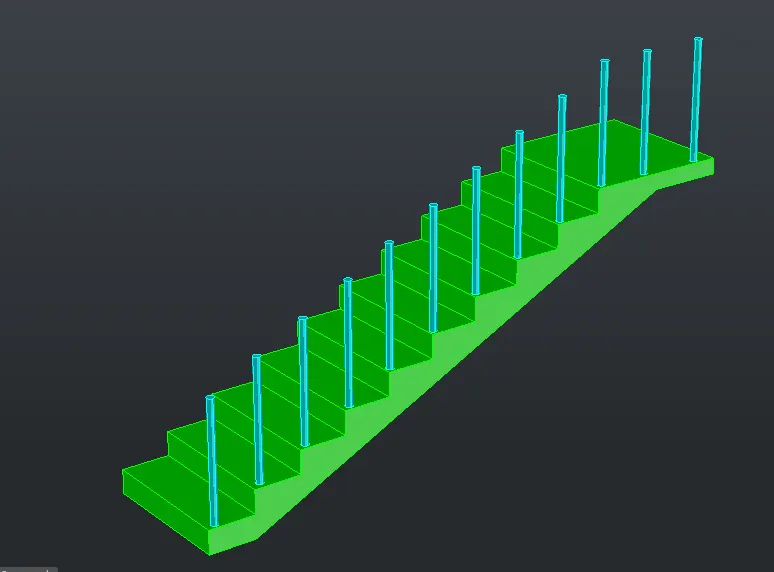
- In command prompt type CIRCLE, create the circle in one thread, and copy it to all the thraeds
- In command prompt type EXTRUDE, extrude the created railings in upward by 2'-6"
- In command prompt type PLINE, arrange the line with the help of ucs on top of the each railing
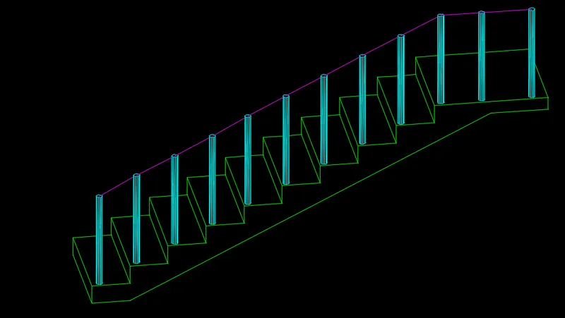
- In command prompt type CIRCLE, create 2" circle near the pline created
- In command prompt type SWEEP, sweep object is circle and path is pline and hand railing is created
- In command prompt type DIML, assign the dimensions
RESULT:
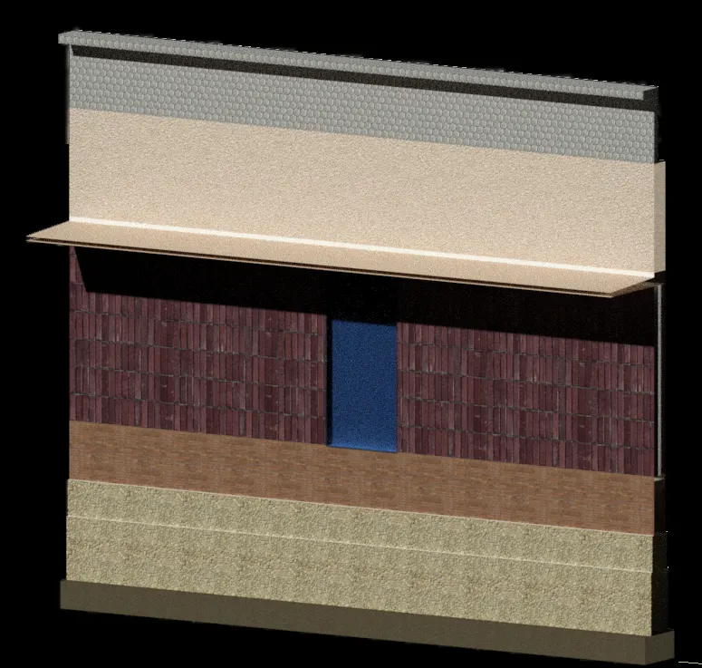
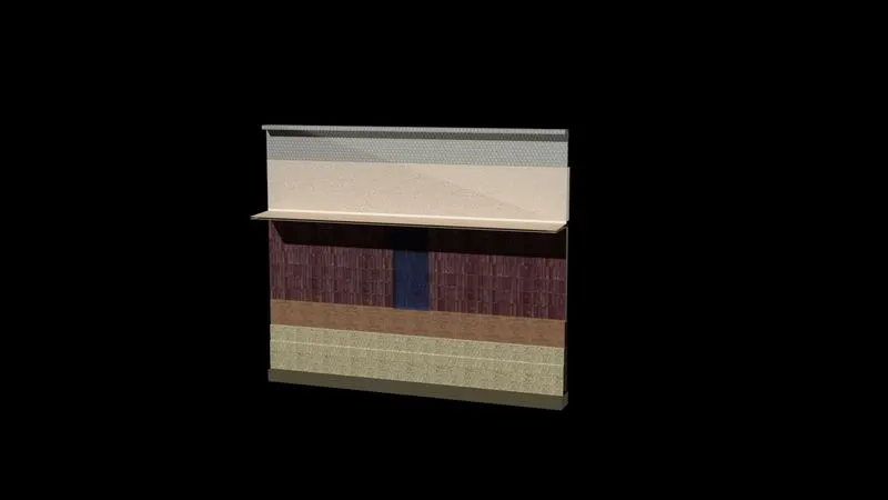
Q4. Create the 3D view of a Wall with spread footing . Create the Door opening only. Assume the size of the parpaet and the coping. See the plans and elevation for the details. Also, create a rendered view of the model with materials as of your choice.
AIM:
To create the 3D view of a wall with spread footing, door opening along with rendered view using Autocad 3D
PROCEDURE:
STEP 1:
- In command prompt type UNITS, set to DECIMAL, precision = 0, insertion scale = MILLIMETERS
- In command prompt type LIMAX and LIMITS set to desired
- In command prompt type ZOOM, All and enter
STEP 2: Drawing the plan in top view
- In command prompt type REC, create the rectangle of dimensions length, width as 300,7500
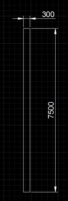
- In command prompt type OFFSET, offset the lines with the help of section details and 3300 from both ends for opening
- In command prompt type TRIM, trim the unwanted lines
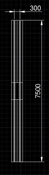
- In command prompt type HATCH, hatch the area by AR-CONC and ARNS131 where ever required
- By using REC, LINE and ARC commands create the door

- In command prompt type DIML, assign the dimensions
- In command prompt type DT, assign the dimensions
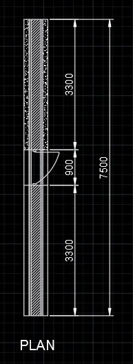
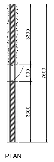
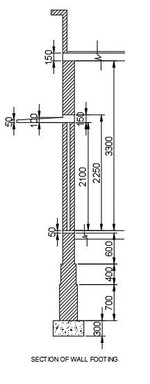
STEP 3: Creation of SECTION in Front view
- In command prompt type LINE, draw the lines as specified in the section view
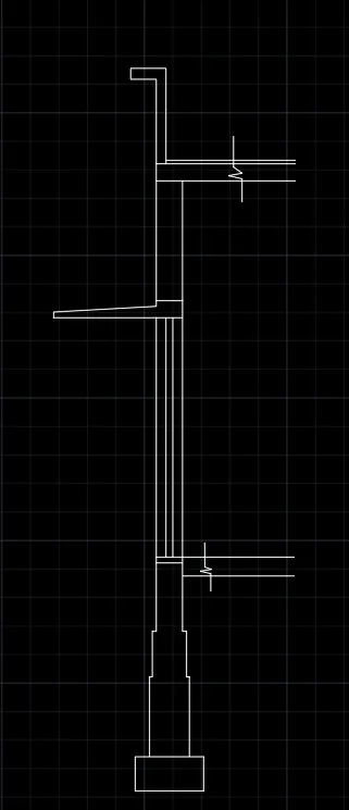
- In command prompt type HATCH, hatches AR-CONC and ANS131 is used
- In command prompt type DIML, dimensions are assigned
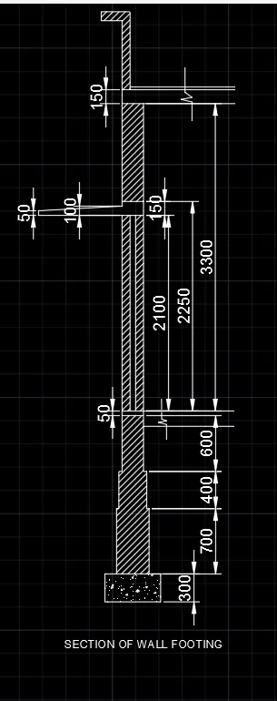
STEP 4: Creation of 3D model of 2d Section view
- In command prompt type REGION, select the section
- In command prompt type EXTRUDE, extrude the section to 7500
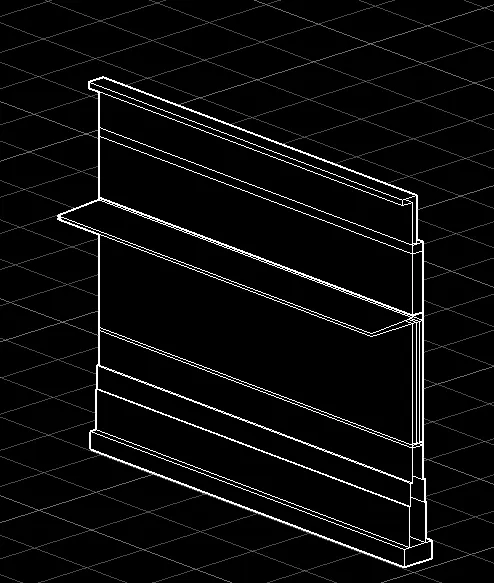
- In command prompt type RMAT, assign the material properties to the created solid section
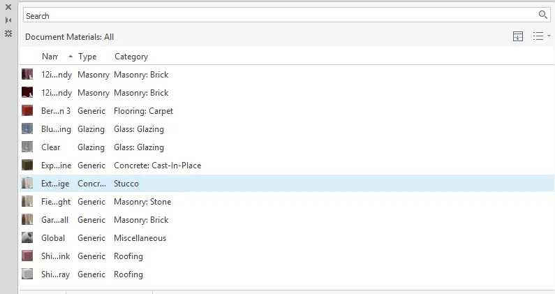
STEP 5: RENDERING of the created section
- In the ribbon, Visualize tab, elect render panel and assign the desired settings
- In command prompt type RR, assign render
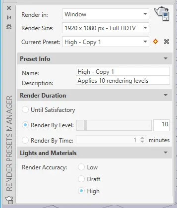
RESULT:
RENDERED IMAGE