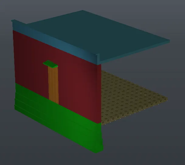
Creating 3D Isometric view of various structural elements in AutoCAD
QUE-. Create a 3D Isometric View of the building with plan and elevation given.
ANS-1
AIM:- TO CREATE A 3D ISOMETRIC VIEW OF THE BUILDING WITH PLAND AND ELEVATION AS PER GIVEN DATA
COMMAND :-
- unit
- line
- hide
- 3dorbit
- solidedit
- copy
- move
- join
- explode
- extrude
- union
- substrac
- material
- rotate
PROSEDURE FOR DRAWING:-
- first open autocad and set limits to the engineering and give pricision of the 0'0".
- now we have to draw plan and elevation as they give in drawing.
- using line command draw plan and elevation.
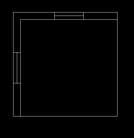
- now draw both side elevation using line command.
- join the elevation line.
- draw the window as per given size and put into the wall.
- now using material command give wooden and glass material to window.
- use solidedit command give colours where required.
RESULT:-GIVEN ISOMETRIC VIEW SUCCESFULLY DRAWEN IN AUTOCAD.
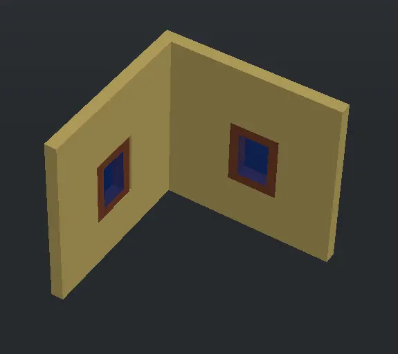
QUE-. Create the 3D View of the Building Façade as given in the plan and elevation. Also, see the detail of the window.
ANS-2
AIM:- TO CREATE A 3D ISOMETRIC VIEW OF THE BUILDING WITH PLAND AND ELEVATION AS PER GIVEN DATA.
COMMAND :-
- unit
- line
- hide
- 3dorbit
- solidedit
- copy
- move
- join
- explode
- extrude
- union
- substrac
- material
- rotate
PROSEDURE FOR DRAWING:-
- first open autocad and set limits to the engineering and give pricision of the 0'0".
- now with the given dimension draw the plan.
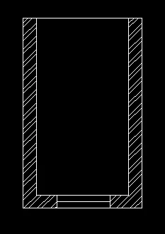
- now using extrude command extrude its to the given height.
- now use hide command for better view.
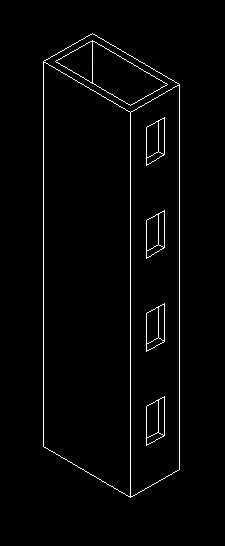
- now we have to draw window as per given dimension.
- after drawing window give material to the window.
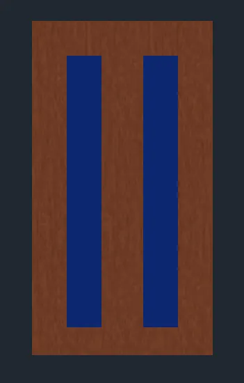
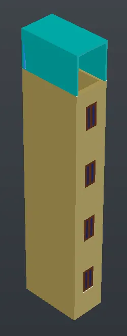
- now put this window to the building and using solidedit command give colour to the building.
RESULT:-GIVEN ISOMETRIC VIEW SUCCESFULLY DRAWEN IN AUTOCAD.
QUE-. Create the ismoteric 3d view of a stair with railing as shown in the plan and elevation. Assume the size of the balustrades and the hand rails.
ANS-3
AIM:- TO CREATE A 3D ISOMETRIC VIEW OF THE BUILDING STAIR WITH PLAND AND ELEVATION AS PER GIVEN DATA.
COMMAND :-
- unit
- line
- hide
- 3dorbit
- solidedit
- copy
- move
- join
- explode
- extrude
- union
- substrac
- material
- rotate
PROSEDURE FOR DRAWING:-
- first open autocad and set limits to the engineering and give pricision of the 0'0".
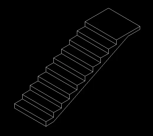
- now using line command draw riser of stairs .
- as per given dimension first draw side elevation.
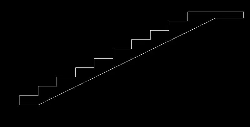
- using join command join all the lines and create one geomatery.
- now take extrude coomand and extrude the geomatery as shown below.
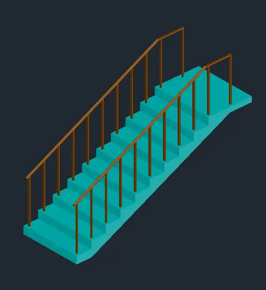
- now we have to draw balustrades and the hand rails by assuming dimension.
- now using material command and solidedit give colour to the staircase.
RESULT:-GIVEN STAIRCASE SUCCESFULLY DRAWEN IN AUTOCAD.
QUE-. Create the 3D view of a Wall with spread footing . Create the Door opening only. Assume the size of the parpaet and the coping. See the plans and elevation for the details. Also, create a rendered view of the model with materials as of your choice.
ANS-4
AIM:- TO CREATE A 3D ISOMETRIC VIEW OF THE WALL WITH SPREAD FOOTING WITH PLAND AND ELEVATION AS PER GIVEN DATA.
COMMAND :-
- unit
- line
- hide
- 3dorbit
- solidedit
- copy
- move
- join
- explode
- extrude
- union
- substrac
- material
- rotate
PROSEDURE FOR DRAWING:-
- first open autocad and set limits to the decimal and give pricision of the 0.0
- now as per all drawing first draw side elevation as they given in drawing.
- now take extrude command and extrude given geomatery.
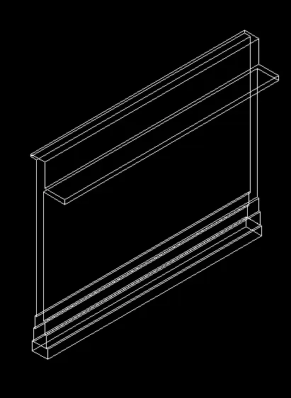
- now as per given dimension draw door and add to the wall.
- after that substrac the door from the wall and add material to the door.
- after that using solidedit command give colours where its neccesary.
- for better view add some llights to the drawing.
- with the realistic view we can see real time view.
RESULT:-GIVEN WALL DRAWING SUCCESFULLY DRAWEN IN AUTOCAD.