Creating 3D Isometric view of various structural elements in AutoCAD
Creating 3D Isometric view of various structural elements in AutoCAD
Introduction : AutoCad is a software, in that we can draw a 2D and 3D models with some tools. The 2D drawing is converted into 3D based on the views.
1.Aim : To Create a 3D Isometric View of the building with plan and elevation given.
Commands used :
- Units
- Limits
- Layers
- 3d orbit
- 3d face
- Dimlinear
- Line
- Rectangle
- Trim
- Extrude
- Region
- Boundary
Step 1 :
- Create a new AutoCAD file with imperial settings.
- Command D - units type as "Engg" and set the precision also
- Set the limits with command "LIMITS" and enter zoom all.
- Command - UNITS to change the unit option as "Engg" and set the precision.
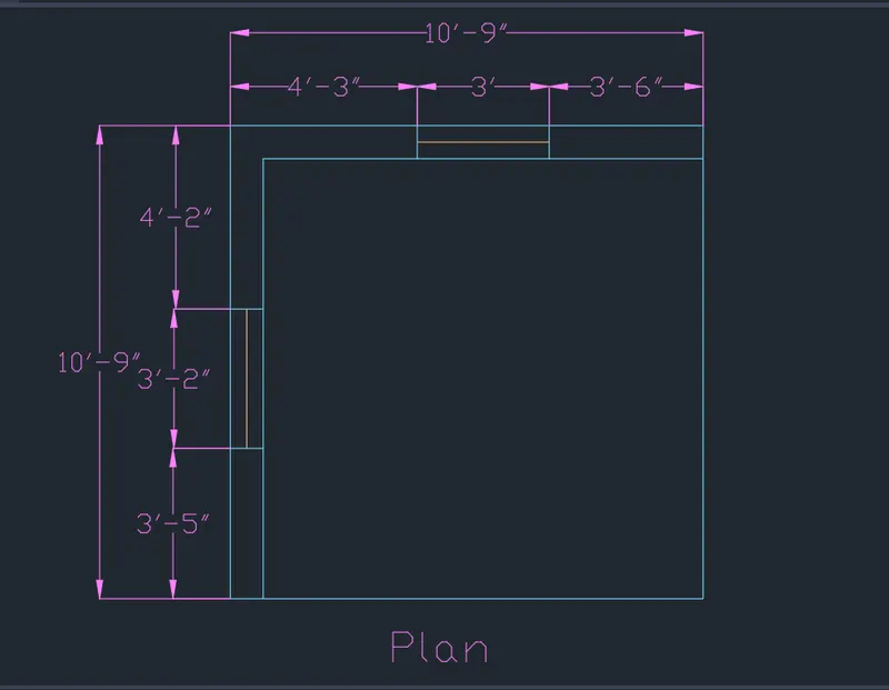
- Command - Rec, select the dimension option and form a wall of size 10'9"
- Command Offset
- Select the object and through option and specify thre offset distance as 9" as wal thickness
- Command - line, Specify the 1st point and draw the window portion as per the plan given at a length of 3' and 3'2" on both sides
- Command - Dimlinear, mark the dimensions as per the plan.
- Select layer from layer properties and form a layer for the objects and the dimensions.
- Command - Text
- Specify the 1st point and enter the height of text and rotation angle and enter the text given.
Step 2 :
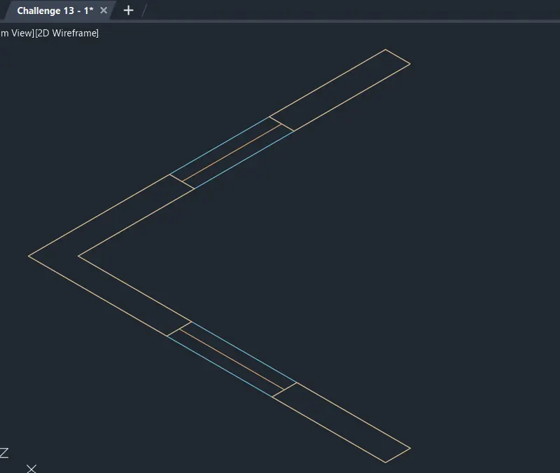
- Select the 3d view option and 2d wireframe
Step 3 :
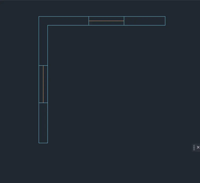
- Command - BO, Select the wall that needed to be done for boundary except the windows
- Command - Region, select the object and form a region so that it can be extruded as a seperate object.
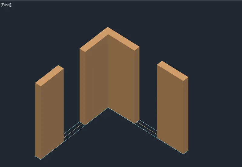
- Command - Extrude
- Selct the object and specify the extruded height of about 10'
- From the top left corner select the option as Shaded.
Step 4:
- Command - Rec
- Draw a rectangle over the wall for window portion
- Select the Extrude tool and Extrude it to the top with a height of 3' to the sill level
- Similarly create another rectangle at the top
- Extrude it into the below level with a height of 3' from the top
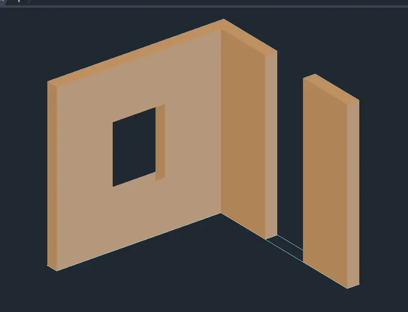
Step 5:
- Command - Rec
- Draw a rectangle over the wall for window portion
- Select the Extrude tool and Extrude it to the top with a height of 3' to the sill level
- Similarly create another rectangle at the top
- Extrude it into the below level with a height of 3' from the top
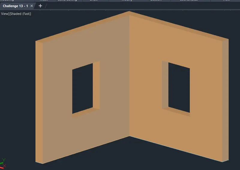
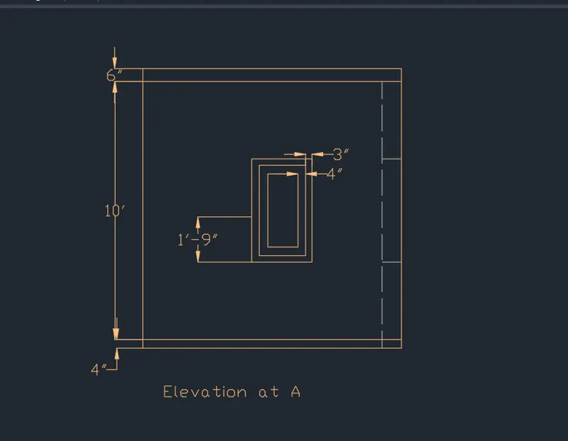
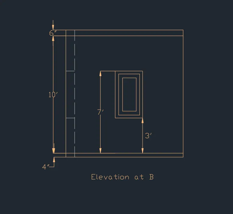
Result : The 3D Isometric View of the building with plan and elevation given has been created.
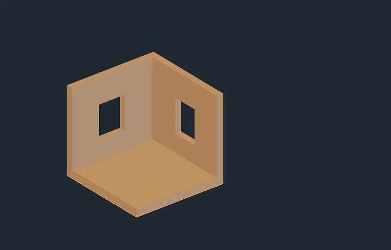
**************
2. Aim : Create the 3D View of the Building Façade as given in the plan and elevation
Commands used :
- Units
- Limits
- Layers
- 3d orbit
- 3d face
- Dimlinear
- Line
- Rectangle
- Trim
- Extrude
- Region
- Boundary
Procedure:
Step 1 :
- Create a new AutoCAD file with imperial settings.
- Command D - units type as "Engg" and set the precision also
- Set the limits with command "LIMITS" and enter zoom all.
- Command - UNITS to change the unit option as "Engg" and set the precision.
- Command - Rectangle in the command box
- Create a rectangle of dimensions 10'9" and 6'9"
- Select the Offset tool and give the offset distance as 9"
- Offset the previous rectangle into the inside as shown
- Select the Line tool and create the window on the right side of the wall as shown.
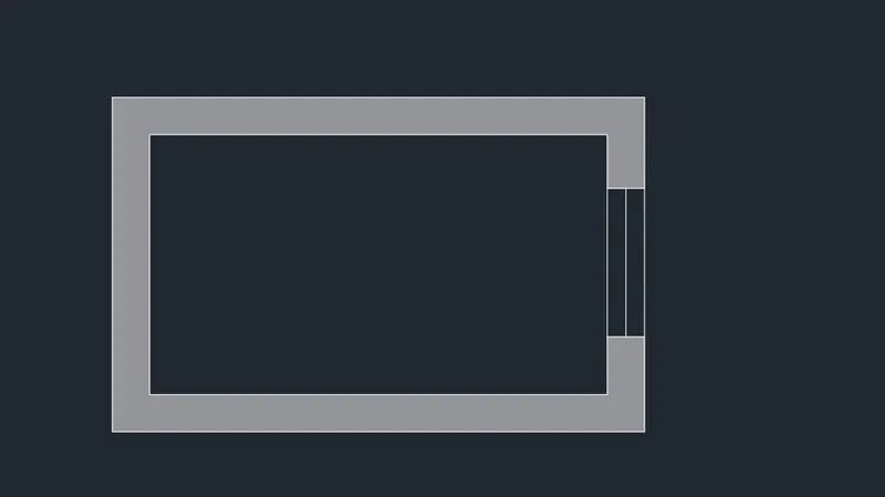
Step 2 :
- Command - BO or Boundary
- Pick the point inside and create the boundary section of the rectangle
- Command - Region or REG in the command box
- Select the Rectangle and press ok to create the region
- Command - Extrude
- Extrude the rectangle at a height of 10'11"
- From the top left corner select the option as Shaded.
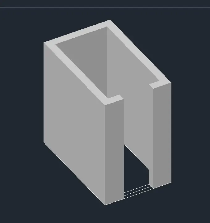
Step 3 :
- Command - Rect
- Select the Extrude tool and Extrude into the top at a height of 4'6"
- create another rectangle at the top of the window portion
- Select Extrude tool and Extrude below with a height of 2'5".
- Command - Rec and draw a rectangle of dimension 4'×3' in the Top view
- Select the Offset tool and give offset distance as 2" for the frame, 3" for mullion, and 1.2" for glass
- Offset the rectangle to the inside
- Command - BO, create a region in the frame, mullion, and glass section respectively
- Using Layer Tool, provide appropriate layers as shown in the figure below
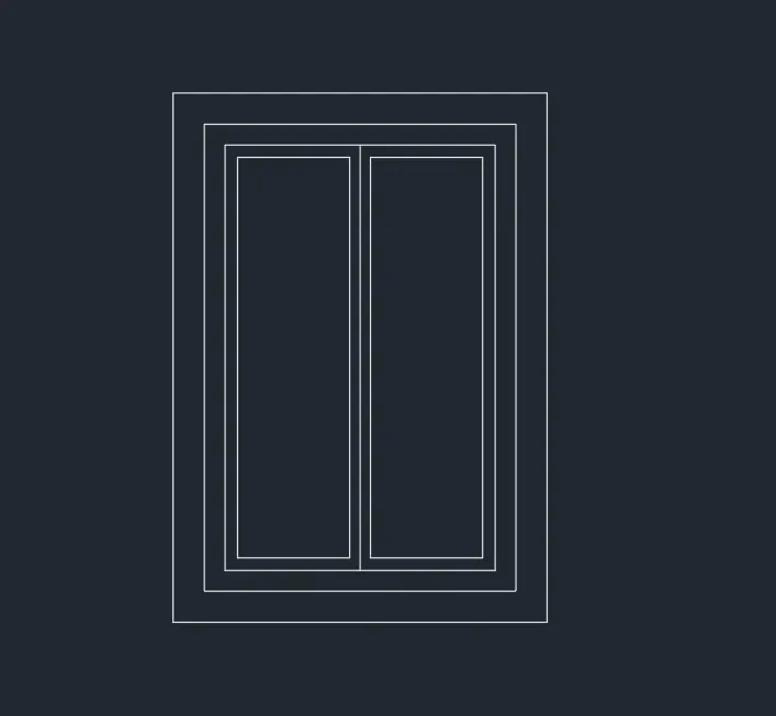
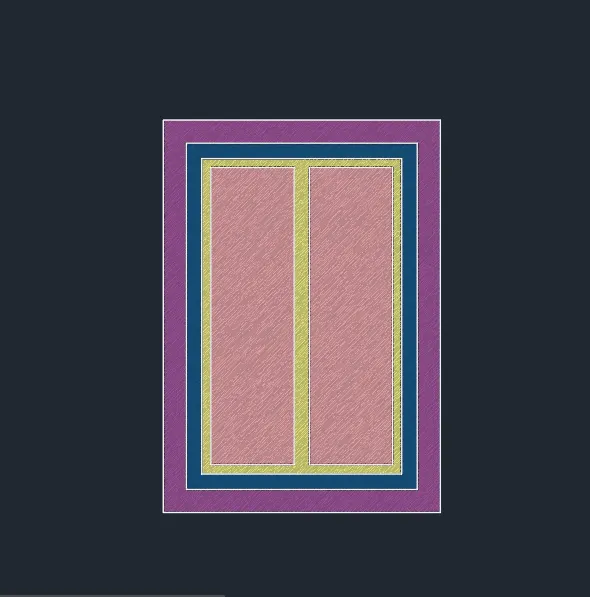
Step 4:
- Command - Copy
- Copy the First floor and move it into the desired location for the four floors and place it as required.
- Command - UCS
- Place the UCS on the top surface of the building
- Draw a rectangle with a dimension of 9"×4" at the top level
- Select the Extrude tool and Extrude the rectangle by 4"
Result : The 3D View of the Building Façade as given in the plan and elevation has been created.
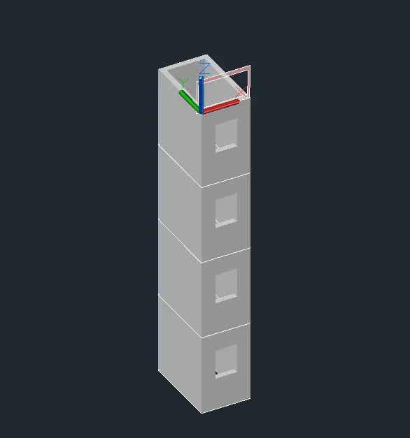
*****************
3. Aim : To Create the ismoteric 3d view of a stair with railing as shown in the plan and elevation
Commands used :
- Units
- Limits
- Layers
- 3d orbit
- Line
- Trim
- Extrude
- Region
- 3dpoly
- Sweep
- 3d move
Procedure:
Step 1 :
- Create a new AutoCAD file with imperial settings.
- Command D - units type as "Engg" and set the precision also
- Set the limits with command "LIMITS" and enter zoom all.
- Command - UNITS to change the unit option as "Engg" and set the precision.
- Command - Line, specify the 1st point
- Draw the rise as 6" and tread as 1'
- Continue the same process to form a stairs.
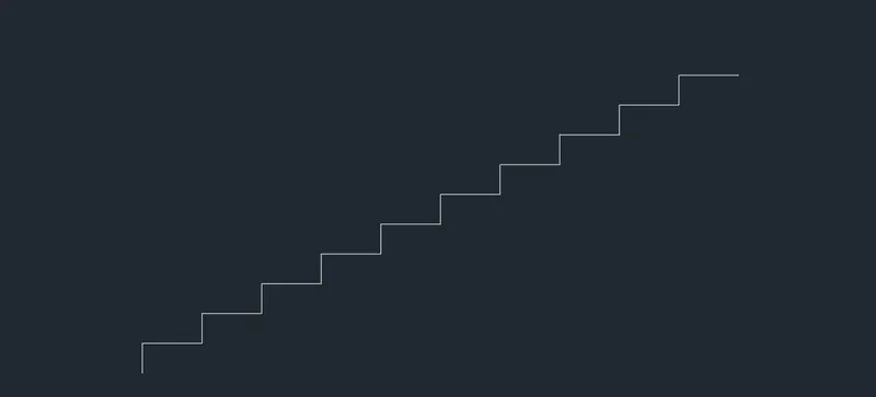
Step 2 :
- Command - Line, specify the 1st point and draw a line of length 3' for the slab
- Draw another line below with the thickness of 4" for the slab
- Join the slab and below tread to form a section of the stairs.
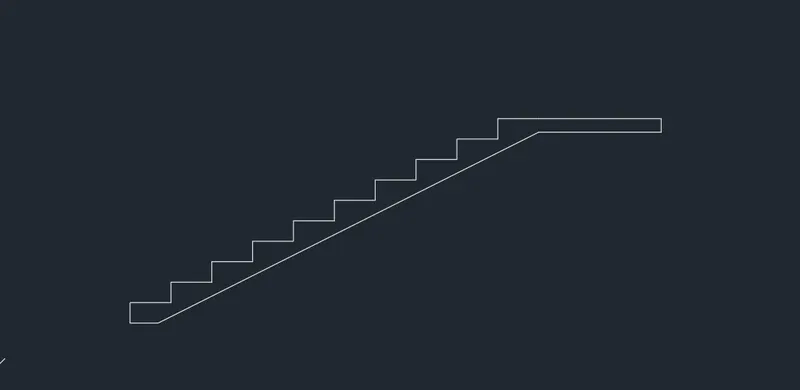
Step 3 :
- Select Default 3D view by using the UCS
- Command - BO to form a boundary and Command - region to create a region
- Command - extrude and Extrude the section to the left side with an extruded height of 3"
- Select the UCS tool by typing UCS in the command box
- Place the UCS icon on the tread to create the handrails
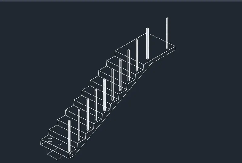
- Command - Circle ,create the circle with a radius of 2" on the tread
- Command - extrude and Extrude the circle with a height of 3'
- Command - Copy, select the object and place the extruded objects on the tread
Step 4 :
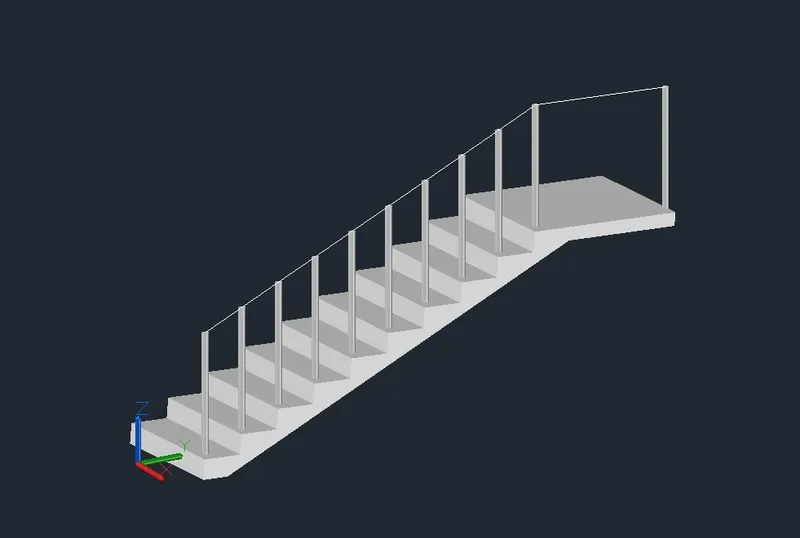
- Command - 3D Poly
- Draw the Polyline starting at the point of the first circular column to the last column
- Draw another circle with a radius of 2" parallel to the circular column
- Select the Sweep tool and select the Circle to sweep it into the Polyline to form a handrail
- From the top left corner select the option as Shaded.
Step 5 :
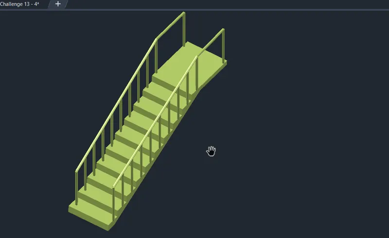
- Command - Mirror in the command box
- Select the handrails and mirror them through the other side
Result : The 3d view of a stair with railing as shown in the plan and elevation has been created.
*****************
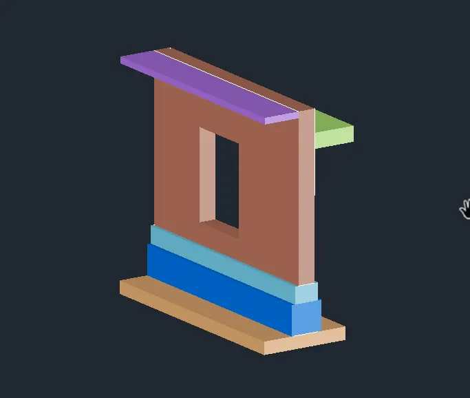
4. Aim : To Create the 3D view of a Wall with spread footing
Commands used :
- Units
- Limits
- Layers
- 3d orbit
- 3d face
- Dimlinear
- Line
- Rectangle
- Extend
- Trim
- Extrude
- Region
- Boundary
- Hatch
Step 1 :
- Create a new AutoCAD file with imperial settings.
- Command D - units type as "Engg" and set the precision also
- Set the limits with command "LIMITS" and enter zoom all.
- Command - UNITS to change the unit option as "Engg" and set the precision.
- Go to Top view
- Command - Line
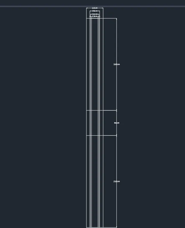
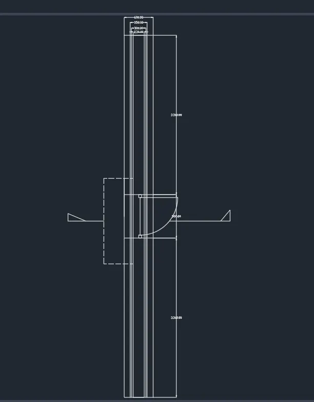
- Draw a vertical line of length 7500mm and 230mm in width
- Draw a center line in the wall and offset 150mm on both sides
- Commnad - Offset and give the offset distance as 25mm
- Select the 300mm line and offset it through outside
- From the center line again give an offset of 300mm and offset it through both sides
- Commnad - Extend, extend the horizontal lines
- Select the Offset tool again and give the offset distance as 3300mm
- Select the horizontal line and offset both sides for the door opening of 900mm
Step 2 :
- Command - Circle create the door opening
Step 3 :
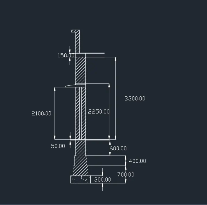
- Select the Hatch tool by typing H or Hatch
- Select Hatch pattern for wall, footing, and for bottom
- Command - Dimlinear option to mark the dimension as per the layout.
Step 4:
- Go to the Default 3D view using the UCS
- Create a profile for the footing step in the 2D plan and copy it through the 3D plan with the help of the Snap tool
- Command - BO and region and pick inside the footing to create the region
- Command - Extrude and Extrude the region by 400mm
- Similarly do the same procedure for the remaining profiles
- To create the top portion of the wall, create the rectangle at the top face
- Select Extrude tool and extrude it to a height of -1050mm
- Command - Union and make the extruded part as the union of the wall.
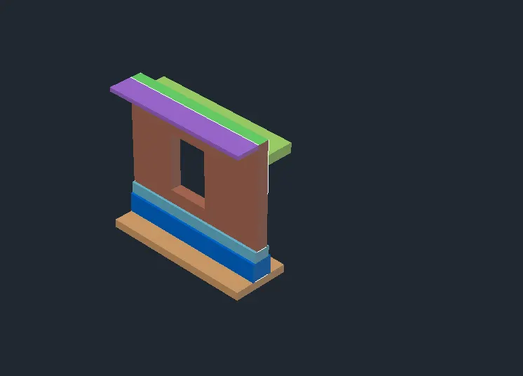
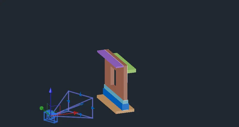
Result : The 3D view of a Wall with spread footing has been created.
**************