Creating 3D Isometric view of various structural elements in AutoCAD
1. Aim: Create a 3D Isometric View of the building
Steps:
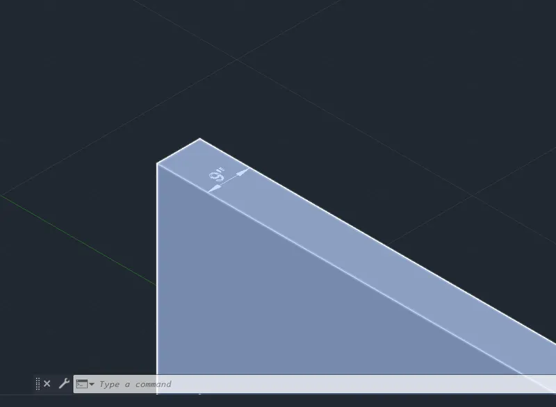
- Create the plan from top view with wall of 9inch thick
- Create a boundary using boundary command [BO]
- Extrude it with height of 10feet .
- Create a boundary on the window and extrude it.
- Join the wall and window extruded
- Create a region of the window top view.
- Give the height of the window from the wall.
- Extrude it with the window height
- Subtract the window space form the wall using subtract tool
- Now draw a top view of window.
- Rotate it
- Extrude it with assume dimension.
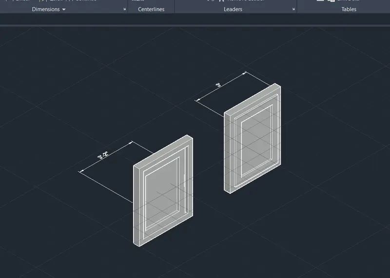
- Now move the window and placed it on the face
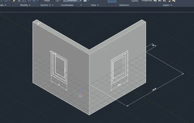
- And give dimensions
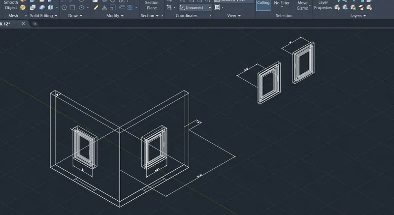
- view in Wireframe
2. AIM: Create the 3D View of the Building Facade
Steps:
- Draw the top view
- Create a boundary on the window and extrude it.
- Join the wall and window extruded
- Create a region of the window top view.
- Give the height of the window from the wall.
- Copy it and placed it in each floor according to there height
- Extrude it with the window height
- Subtract the window space form the wall using subtract tool
- Now draw a top view of window.
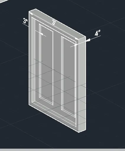
- Rotate it
- Extrude it with assume dimension.
- Now place it on the face of the wall
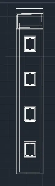
- Shaded:
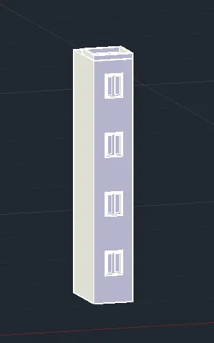
- This is the conceptual view of the drawing
3. Aim; Create the ismoteric 3d view of a stair with railing.
Steps;
- Draw the sketch of staircase with given dimention from top view
- Rotate it
- Extrude it with width of 3ft.
- Create a circle for the railing
- Create region of the circle and extrude it.
- Copy it ,choose a base point and place it in each steps
- Now join the railing with a polyline.
- Sweep it wih another circle using sweep tool.
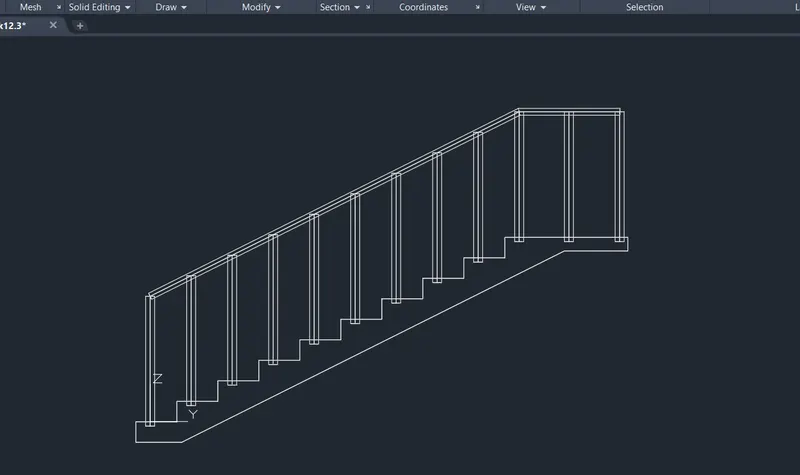
- This is the right view of the staircase.
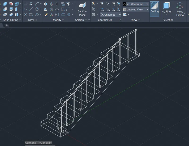
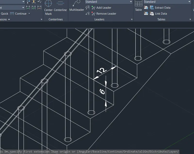
- The image shown above are the 3D isometric view showing dimension.
4. Aim:Create the 3D view of a Wall with spread footing
Steps:
- Create layer for each element
- Layer for wall, slab,cantiliver, foundation.
- Create the footing of the wall in 2D
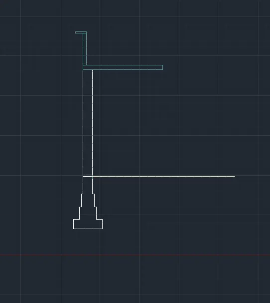
- Rotate it
- Create a region for each element with the layers
- Extrude it with distance of 7500mm
- Now using UCS command the front view is given as X-Y view.
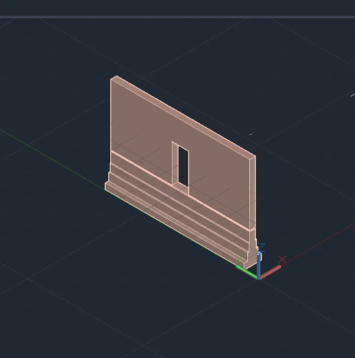
- Create a door with a heigth of 2100 and width of 900 .
- Then create a boundary and extrude it .
- Subtract the door from the wall.
- Now Create the slab and cantilver
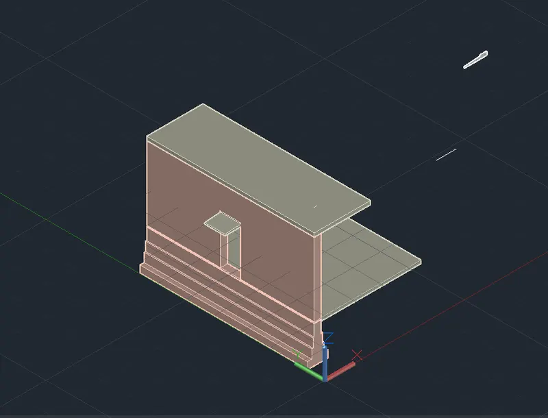
- Now complete the drawing and extruding the top wall .
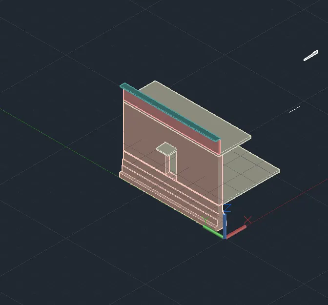
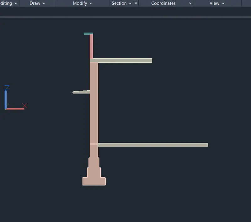
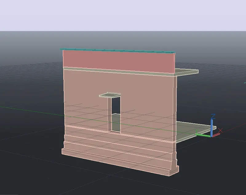
- This is the side view.
- Now create a camera view by creating a cylinder for the camera stand
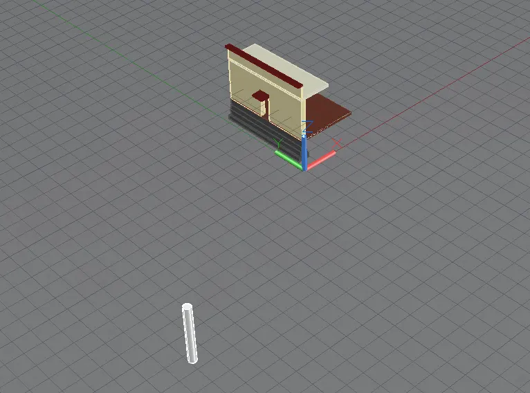
- Place the camera on the top of the cylinder.
- And set the view, height, lens ,target.
- This is the view of camera.
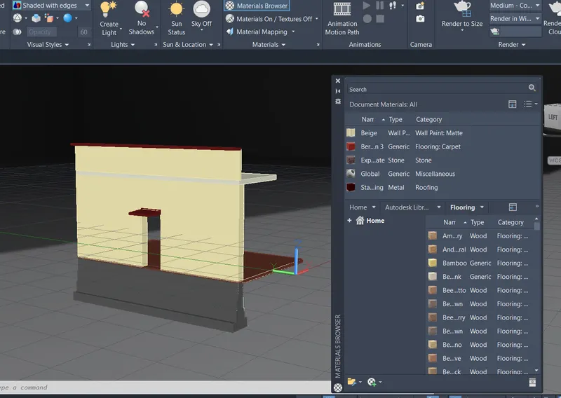
- Now select material for each element using the command[RMAT].
- Rendering process:
- Select environment
- Adjust exposure
- Size of render
- Go to properties
- Make an adjustment
- Render it
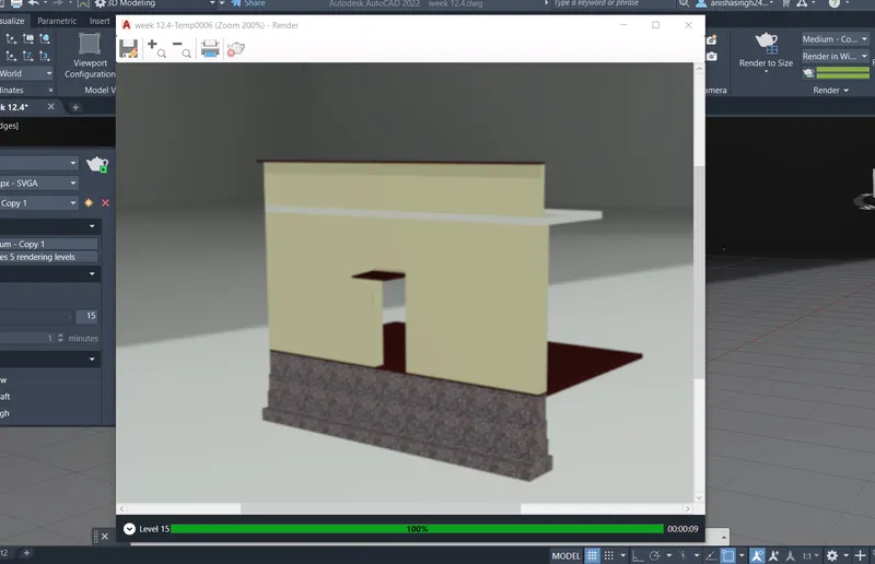
- So this is rendered.