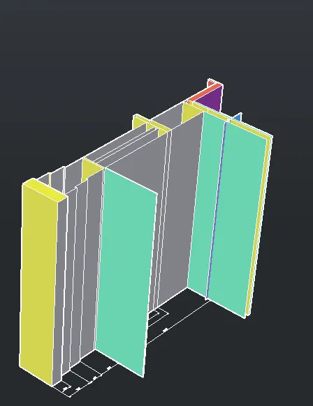
Creating 3D Isometric view of various structural elements in AutoCAD
CHALLENGE 13:
Creating a 3D Isometric view of various structural elements in AutoCAD.
AIM:
To Create a 3D Isometric view of various structural elements in AutoCAD.
INTRODUCTION:
This 3D modeling has 3 types of modeling techniques they are, wireframe modeling, solid modeling, and surface modeling. Creating various 3D Models like Furniture, Footing, Girder, Column drop with panels, and Gable Walls in AutoCad.The commonly used commands to create this 3D model are the 3D face,3Dorbit, and Solid modeling techniques like Box, poly solid, Extrude, revolve, sweep, union, and subtract commands. To create a 3-dimensional view for solid edit, rotate 3d commands are most used in 3d modeling.
QUESTION NO:1
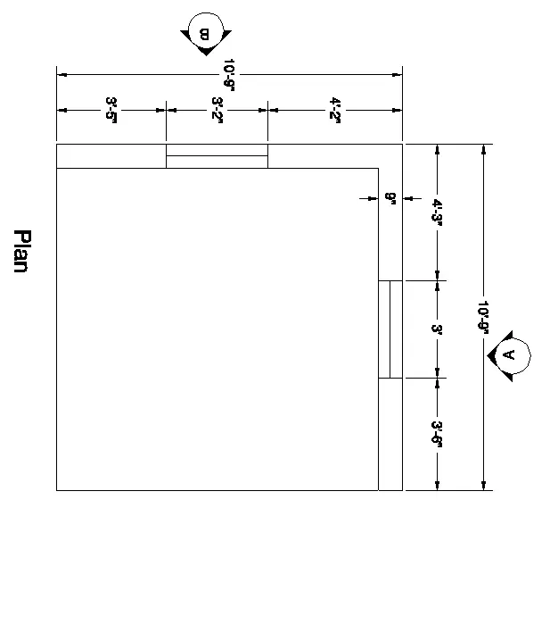
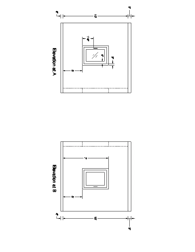
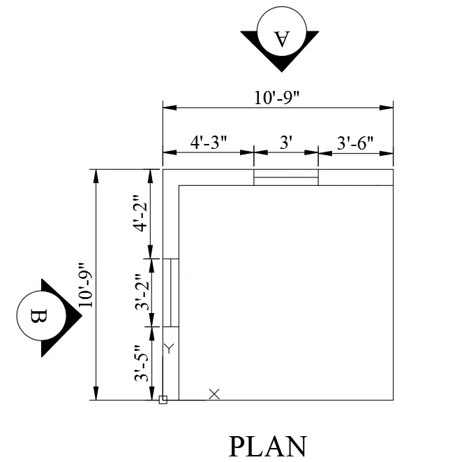
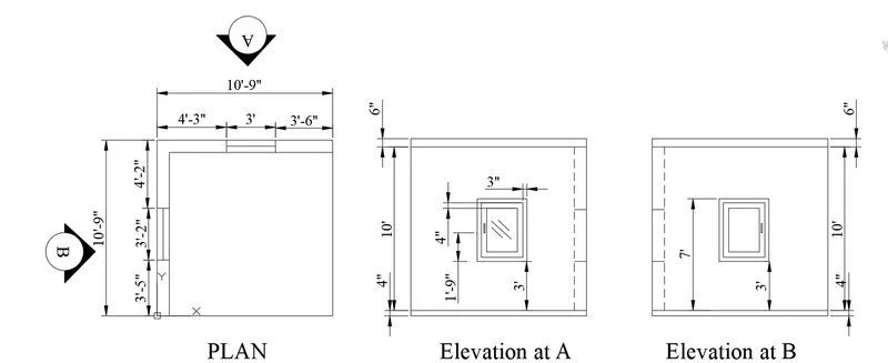
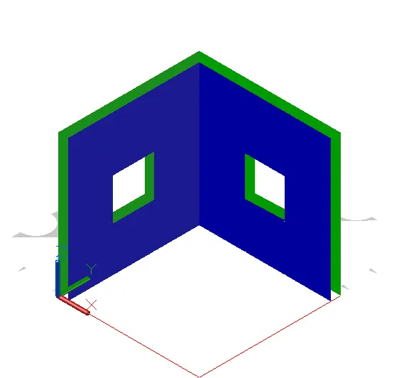
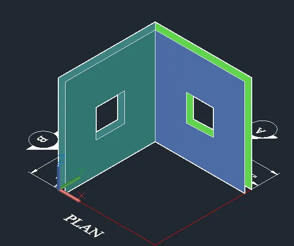
Create a 3D Isometric View of the building with the plan and elevation given.
PROCEDURE:
- Open AutoCAD software and open a new drawing.
- Set the necessary limits and units.
- To change the workspace in 3d basics and 3d modeling.
- Set view cube and UCS in the workspace.
- Type the REC command window and press enter

- Specify the first point: Type (0,0) at the command prompt and press enter(starting point)
- Specify the Next point: Type (@10'9",10'9") at the command prompt and press enter to create a rectangle.
- Now offset the distance 9" by the offset command in the command prompt.
- After that create windows having sizes of 3'2" and 3' by using offsetting the lines.
- Extra lines are trimmed by using the trim command.
- After providing all dimensions and text required to plan.
- Now complete the plan.
-
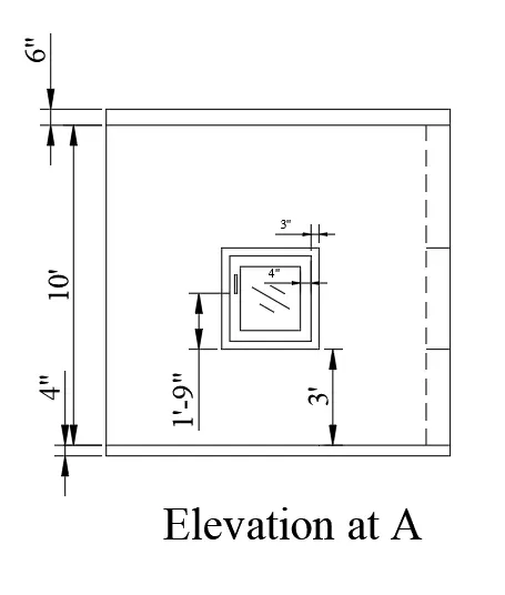
- After that draw the elevations A and B.
- Now draw the line parallel to the plan and offset line distances 4",10' and 6" to draw the rectangle based on these lines.
- Now create window elevation at a height of 3'.
- Window panels to create set distances of 3" and 4" respectively.
- Now complete the Elevation at A.
-
- Now Mirror elevation A, to create elevation at B and then the remaining extra lines are trimmed to provide dimensions.

RESULTS:
3D view:
QUESTION NO:2
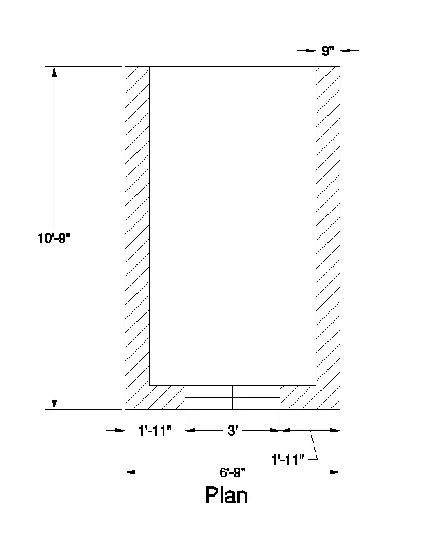
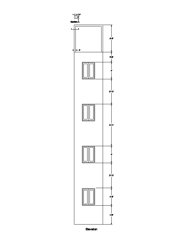
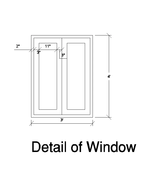
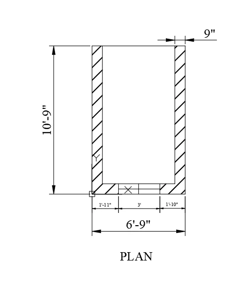
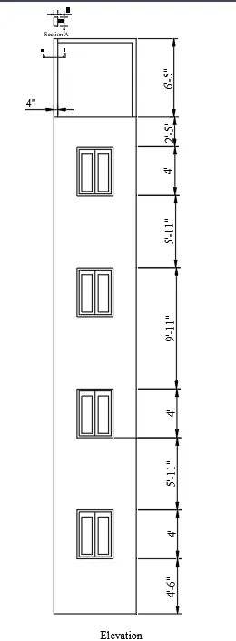
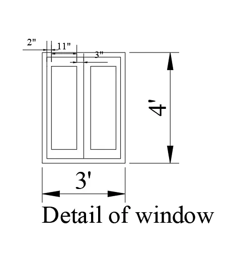
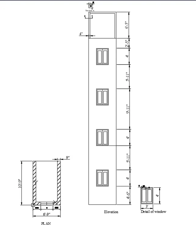
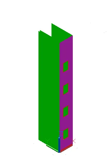
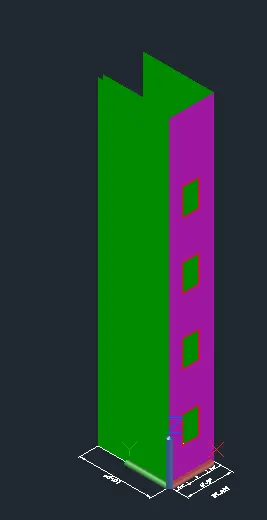
Create the 3D View of the Building Façade as given in the plan and elevation. Also, see the detail of the window.
PROCEDURE:
- Open AutoCAD software and open a new drawing.
- Set the necessary limits and units.
- To change the workspace in 3d basics and 3d modeling.
- Set view cube and UCS in the workspace.
- Type the REC command window and press enter
- Specify the first point: Type (0,0) at the command prompt and press enter(starting point)
- Specify the Next point: Type (@6'9",10'9") at the command prompt and press enter to create a rectangle.
- Now offset the distance 9" by the offset command in the command prompt.
- Now explode all rectangles and left vertical lines to offset the 1'11" and 3' to create a window at the center point.
- Hatching is provided by using the Hatch command.Extra lines are trimmed.
- To provide all dimensions of the plan.
- Now complete the plan of a section.
- Now draw the elevation.
- Now draw the line and offset the distances 4'6".4',5'11",4',9'11".5'11",4',2'6' and 6'5".
- To create a window as per the required size and copied to all required places.
- Now take the section at the top portion to draw the rectangle 4"x9" respectively.
- Now provide the all dimensions and annotation.
-
- Now draw the detail of the window.
- Window size details are 3'x4' and panels offsetting is 3",11", and 3" respectively.
- Provide all dimensions.
-
RESULTS:
3D VIEW:
QUESTION NO:3
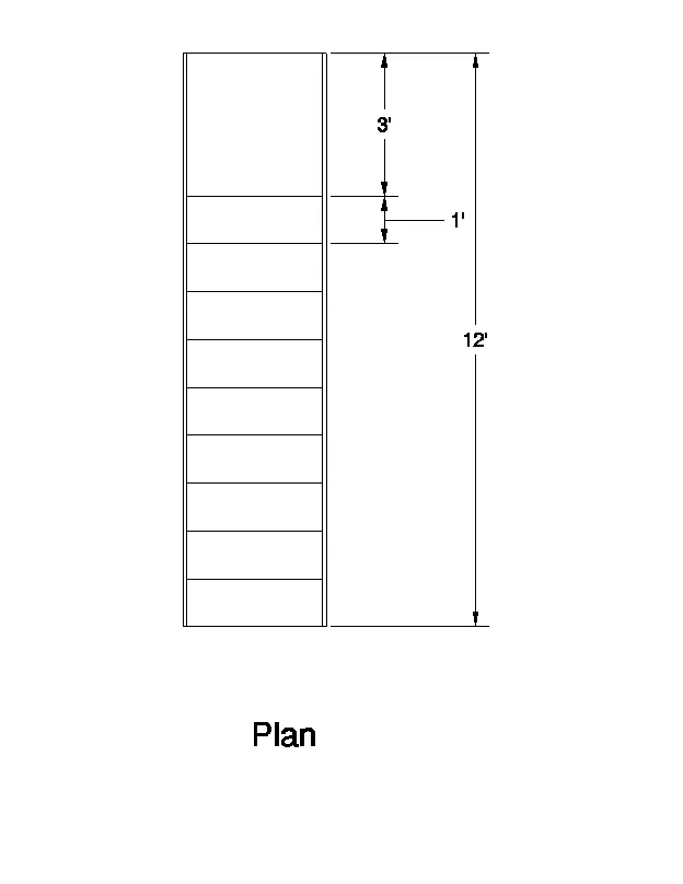
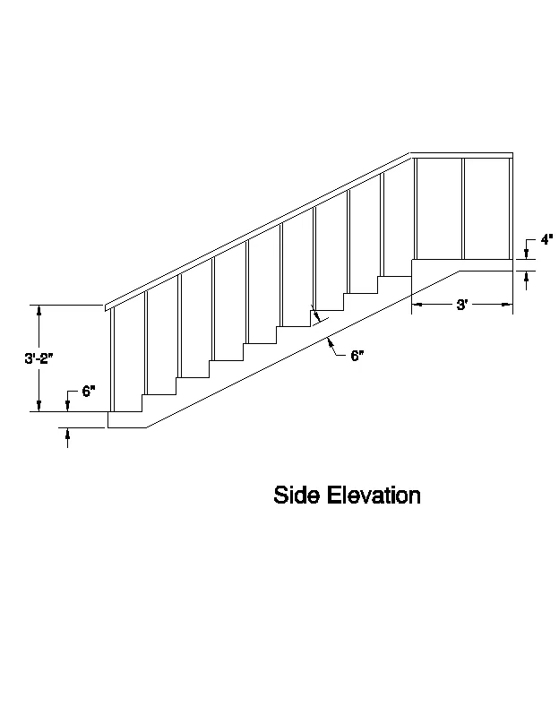
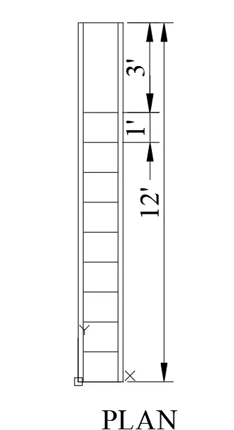
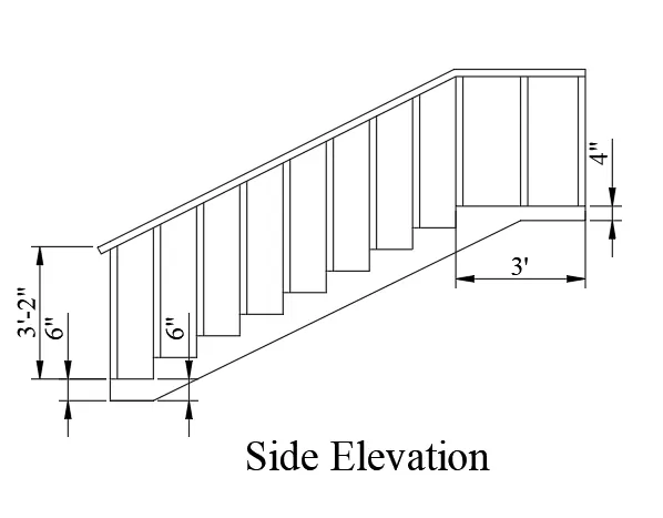
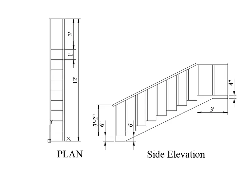
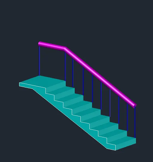
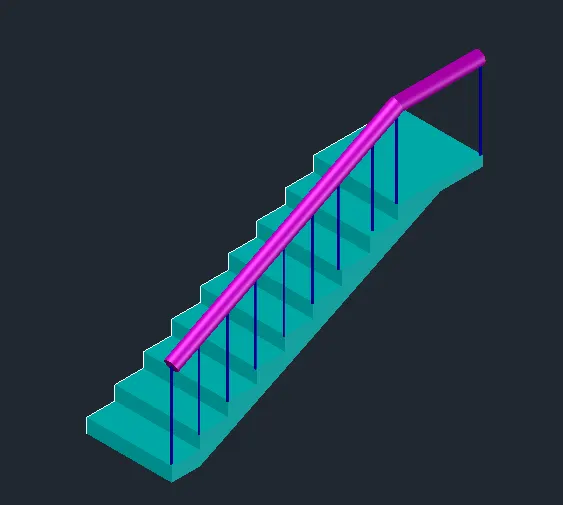
Create the isometric 3d view of a stair with a railing as shown in the plan and elevation. Assume the size of the balustrades and the handrails.
PROCEDURE:
- Open AutoCAD software and open a new drawing.
- Set the necessary limits and units.
- To change the workspace in 3d basics and 3d modeling.
- Set view cube and UCS in the workspace.
- Type the REC command window and press enter
- Specify the first point: Type (0,0) at the command prompt and press enter(starting point)
- Specify the Next point: Type (@1.5',12') at the command prompt and press enter to create a rectangle.
- Now offset the distance 2" by the offset command in the command prompt.
- After that offset the distance of 1' for rails for staircases up to 9 steps.
- Now provide all dimensions and trim the extra lines.
-
- Now draw the side elevation for the staircase.
- Now draw the 6" line for the rise and 1' for the tread and now copied to the total 9 steps.
- After that draw the landing up to 3' and similarly draw to the handrails as required sizes are shown in the elevation.
- After that provide all dimensions and annotations.
-
RESULTS:
3D VIEW:
QUESTION NO:4
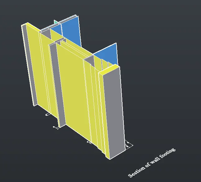
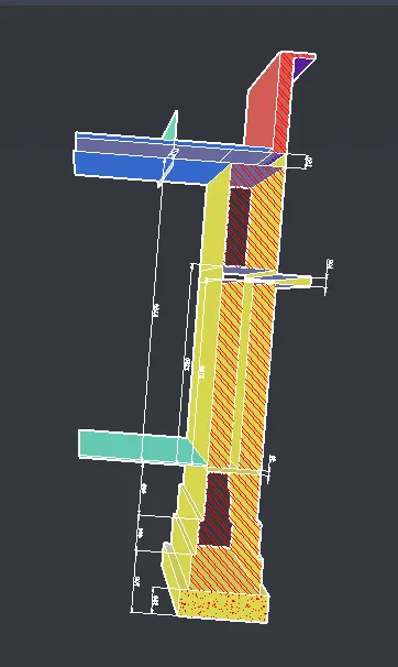
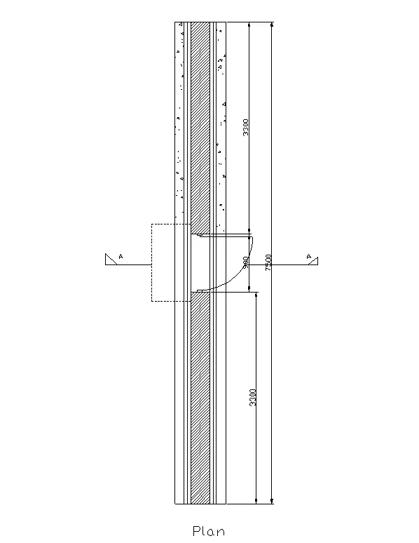
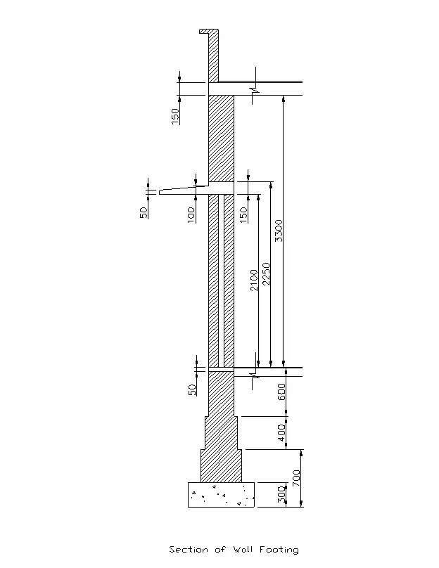
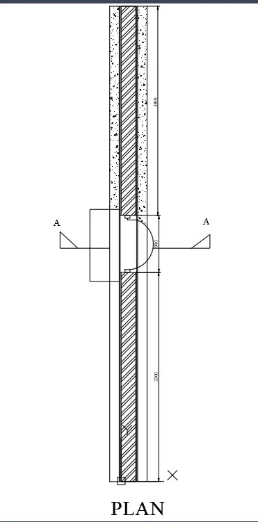
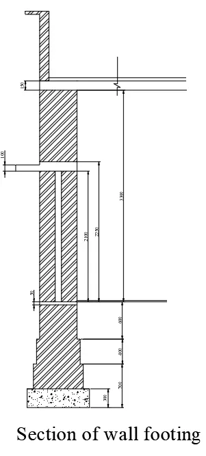
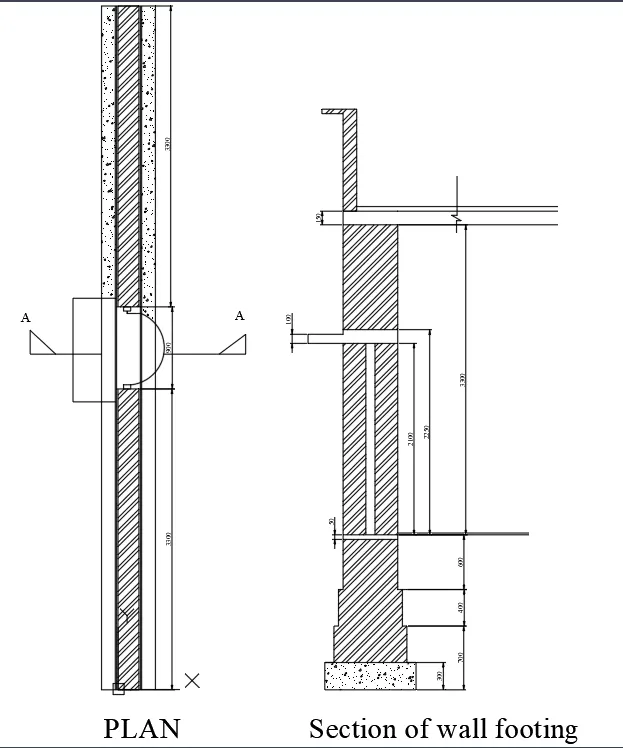
Create the 3D view of a Wall with spread footing. Create the Door opening only. Assume the size of the parpaet and the coping. See the plans and elevation for the details. Also, create a rendered view of the model with materials of your choice.
PROCEDURE:
- Open AutoCAD software and open a new drawing.
- Set the necessary limits and units.
- To change the workspace in 3d basics and 3d modeling.
- Set view cube and UCS in the workspace.
- Type the REC command window and press enter
- Specify the first point: Type (0,0) at the command prompt and press enter(starting point)
- Specify the Next point: Type (@230mm,7500mm) at the command prompt and press enter to create a rectangle.
- Now offsetting the line's required sizes.
- To create a window of size 230mmx 900mm.
- Hatching is provided for the brick wall and concrete portion by using the hatch command.
- Now provide all dimensions and annotation.
-
- Now create a section of a wall footing.
- Now draw the footing details, firstly draw a rectangle size of 1000x300. Now draw the line having the required dimensions shown in the section.
- Hatching is provided for the wall portion and concrete portion by using the Hatch command.
- Now provide all dimensions for the section view.
-
RESULTS:
3D VIEWS: