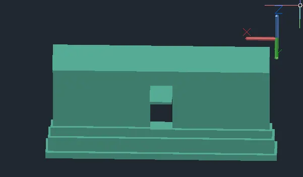
Creating 3D Isometric view of various structural elements in AutoCAD
1) Ans
Create a 3D Isometric View of the building with plan and elevation given
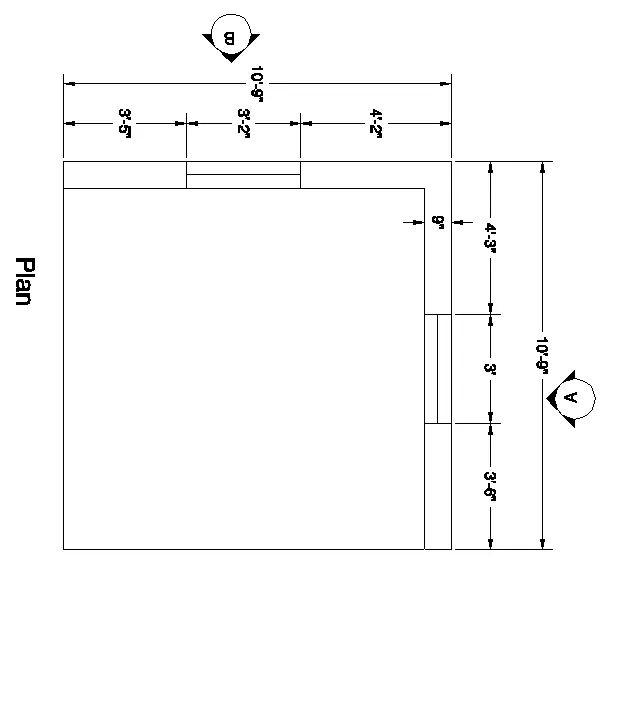
AIM : To Draw the 3D Isometric view of the building as show in the figure
Intriduction: A planview of wall and two evevation views one is of a window details and second is of floor level elevations are given and they are to be converted into 3D model.
2 window details regarding the frame diamensions mullion dimension and handle heigh.the thickness of bottom floor and top roof are aslo given as respectively the height og floor is give 10' heigh of window from floor 3'
Procedure:
Open autocad
Type un (Unit) entra command box
Change units to Engineering in 0'-0" scale in Inches
Change the workshop setting of autocad from drafting and annotation 3D modeling.
Step-1
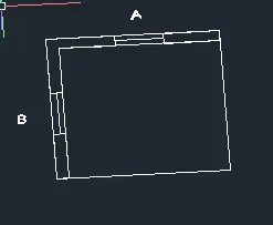
- Entra the Rec (Rectangle) command as shown in figure
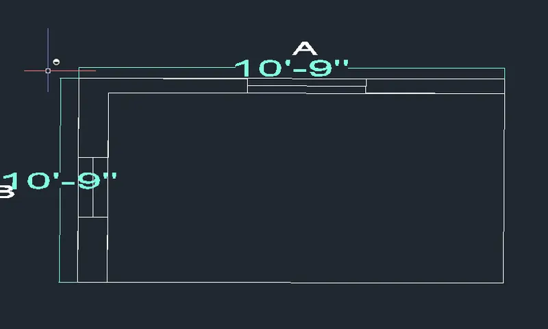
- next draw a rectangle box in commands in 10'-9",10'-9"
- Entra the offset command in 9"
- entra the trim command and trim the boundray
Step-2
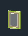
- Draw the window of the size in 3' X 4' as shown in the below figure
- Draw the this window using the rectangle command and offset the 3" and again offset 4"
- Entra the extruded using.
Step-3:
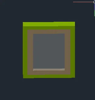
- Draw thw window of the size 3'-2" x 4' as shown in figure
- we draw the this window using the rectangle command and offsite 3" and again 4"
- Etra the extureded command using
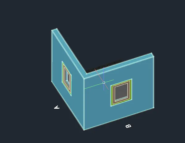
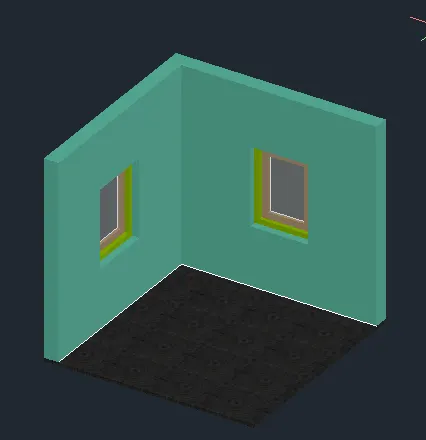
- Draw to walls in using extrude command as shown in figure.
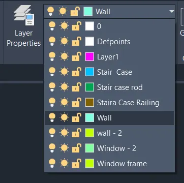
- apply layer for the providing the colour to them
- next we attache the craeted window to the wall show in figure
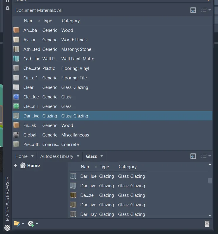
- Using the flooring materals in tiles
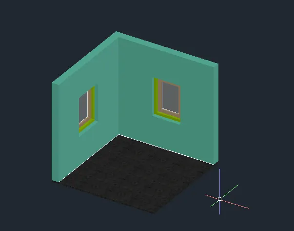
RESULT:-
2)Ans
Create the 3D View of the Building Façade as given in the plan and elevation. Also, see the detail of the window.
AIM:-
TO Create the 3D view of the building facade as give in the paln and elevation and need to create the window.
INTRODUCTION:-
1. Isometric drawing is a 3D representation of an object, room, buiding or desing on a 2D surface
Step-1:
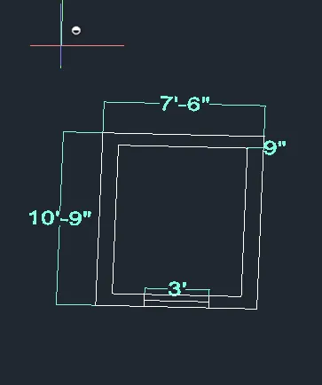
1.Entra the rectangle using the rectangle command and offset command using 9", as shown in the figure
2. Next we have draw the window of size 3'-2"
Step-2:
3.Next we used in region coomand and select the object, then press enter
4. Next we need to extrude the plan using the extrude command with th height of 40'-10"
5.next we need to subtract the four window portion vertically in a building facade with the distance 5'-11" with the window size 3' X 4'
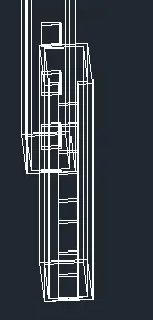
Step-3:
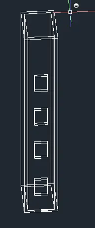
6. Next using union command and press entre
7. then after select the total drawing and press enter
8. Next the window protion will be clearly visible in the building facasde as showin in the below figure
Step -4:
9. Next we select the custom visual style as shande with edges as shown in figure
Step -5:
10. Next provided the layers the building facade of colour as shown in figure.
Step -6:
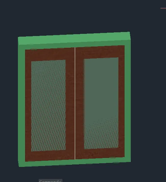
11. Next we draw the window of the size 3'-2" X 4' shown in figure
12. draw the this window using the line command exturede using the extured command
13. Next we use 3D orbit command to view the froth elevation as shown in figure
RESULT:
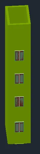
The given 3D isometric view of the building facade is draw successfully in the autocad in detailed manner.
3) ANS
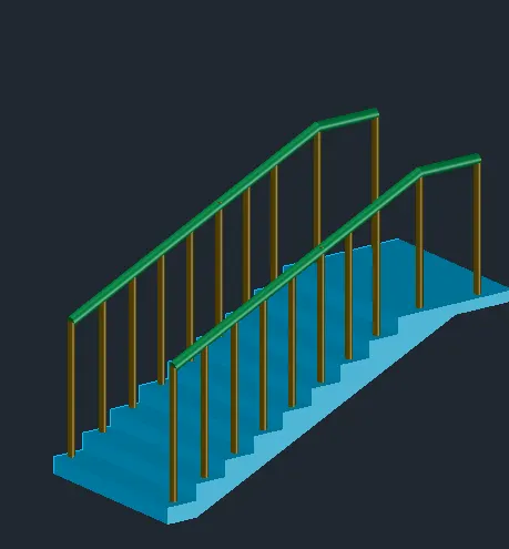
Create the ismoteric 3d view of a stair with railing as shown in the plan and elevation. Assume the size of the balustrades and the hand rails.
AIM: To Create the isometric 3D view a stair case with railing as shown in the plan and elevation.
INTRODUCTION:
An isometric drawing is a 3D respesentation of an objecti, room, building, stair case or design on 2D surface
PROCEDURE:
STEP - 1
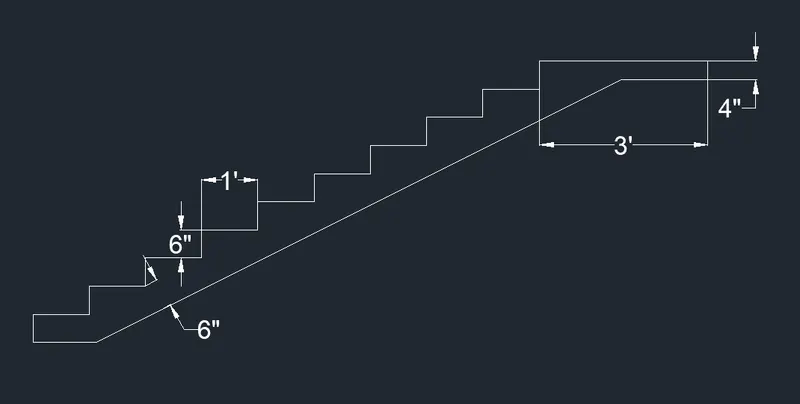
1. Draw the stairs Using the line command
2. We draw the stair case with the rise 6" and tread of 1' as shown in figure
STEP- 2
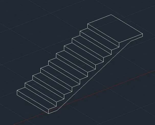
3. Next use the 3Drotated to rotated the figure from the step- 1
4.Next use the exture command to extrude the rotated figure to from the stiar in3D view
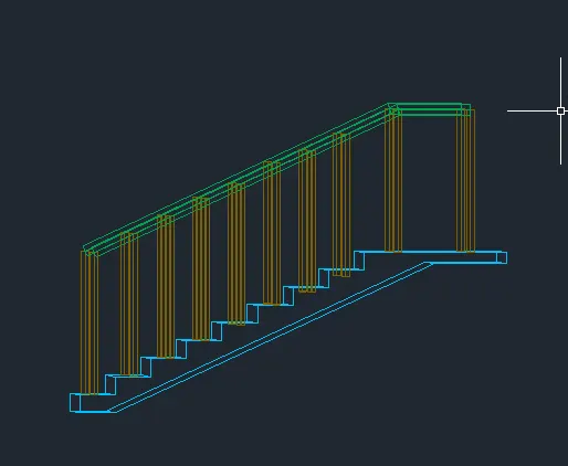
5. Next draw the railing using the circle
6. next we show the stairs in the side view using the 3D roated command as shown figure below figure
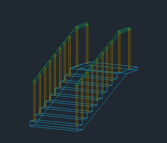
7. now the stair case in the 3D isometric view using the 3Dorbit command as shown in figure below figure.
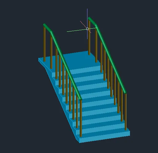
RESULT:
The given 3D isometric view of the stair is draw successfully in the autocad in detailed manner.
4)ANS
Create the 3D view of a Wall with spread footing . Create the Door opening only. Assume the size of the parpaet and the coping. See the plans and elevation for the details. Also, create a rendered view of the model with materials as of your choice.
AIM:
To create the 3D view of a wall with spread footing and need to create a rendered view of the model with materials.
INDRODUCTION:
An isometric drawing id 3D representation of an object, room, building, stairs of design on 2D surface.
PROCEDURE:
1. Change the unit in engineering to Decimal and take the precision as 0
2. Next have to draw plan of wall with spread footing with given dimensions as shown in the figure
3. Next draw the 3D isometric view of the wall with spread footing using the extrude command
4. Next provide the layer for the wall with spread footing with colouras shown in figure