Creating 3D Isometric view of various structural elements in AutoCAD
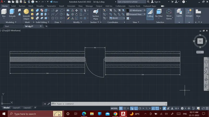
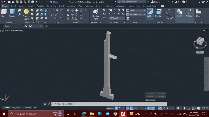
Aim: To create a 3D Isometric View of the building
Introduction: AutoCAD is three-dimensional CAD software that is used commercially across the world.
Procedure:
- first make the diagram in the 2d wireframe with the help of line command
- then make the elevation A & B of the diagram
- then make it into region after that extrude from the given size
result:
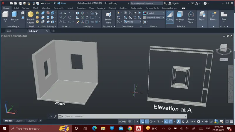
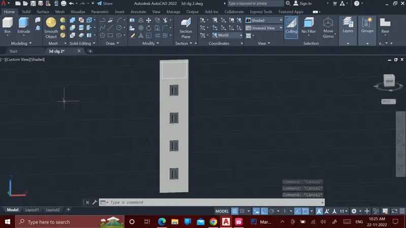
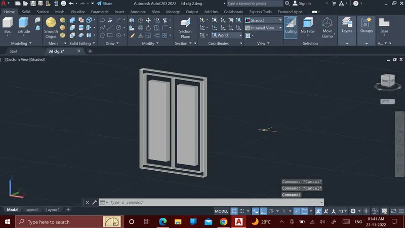
Aim: To create the 3D View of the Building Façade as given in the plan and elevation.
Introduction: AutoCAD is three-dimensional CAD software that is used commercially across the world.
Procedure:
for figure 1
- first make the diagram in the 2d wireframe with the help of line command
- then make it into region of complete figure after that extrude the figure from the given size
for figure 2
- first make the diagram in the 2d wireframe with the help of line command
- then make it into region of complete figure after that extrude the figure from the given size
for figure 3
- first make the diagram in the 2d wireframe with the help of line command
- then use rotate3d command at an angle of 90
- then make the region of complete figure and use subtract command
- after that extrude the complete figure
result:
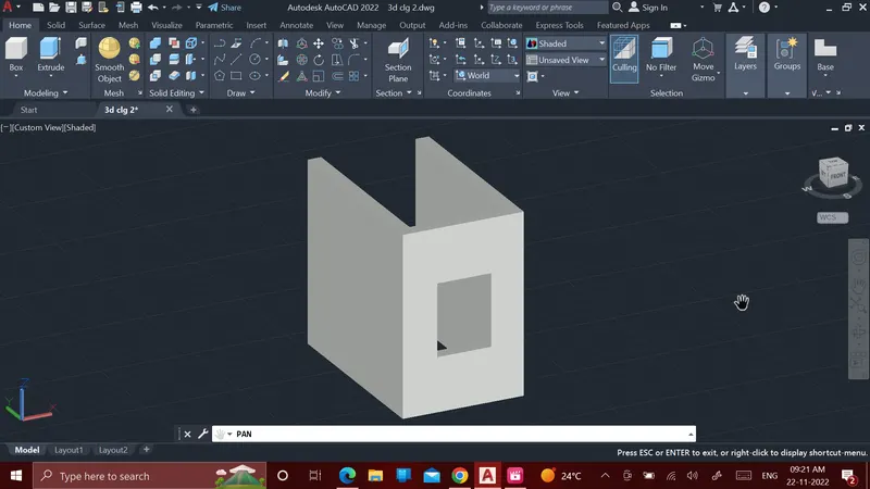
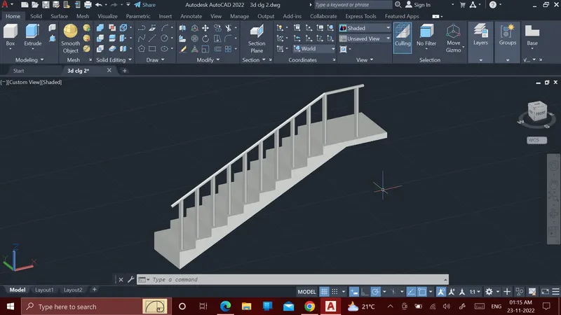
Aim: To create the isometric 3d view of a stair with railing as shown in the plan and elevation.
Introduction: AutoCAD is three-dimensional CAD software that is used commercially across the world.
Procedure:
- first make the diagram in the 2d wireframe with the help of line command
- then use rotate3d command at an angle of 90
- then make the region of complete figure and make the cylinder
- after that extrude the complete figure
- then take the 3d polyline and joint the midpoint of each cylinder
- then take sweep command and make it a cylinder
result:
Aim: To create the 3D view of a Wall with spread footing. Also, create a rendered view of the model with materials as of your choice.
Introduction: AutoCAD is three-dimensional CAD software that is used commercially across the world.
Procedure:
- first make the diagram in the 2d wireframe with the help of line command
- then use rotate3d command at an angle of 90
- then make the region of complete figure
- after that extrude the complete figure
- then go to visualize select the materials then the material dialog box will open to choose the material
result: