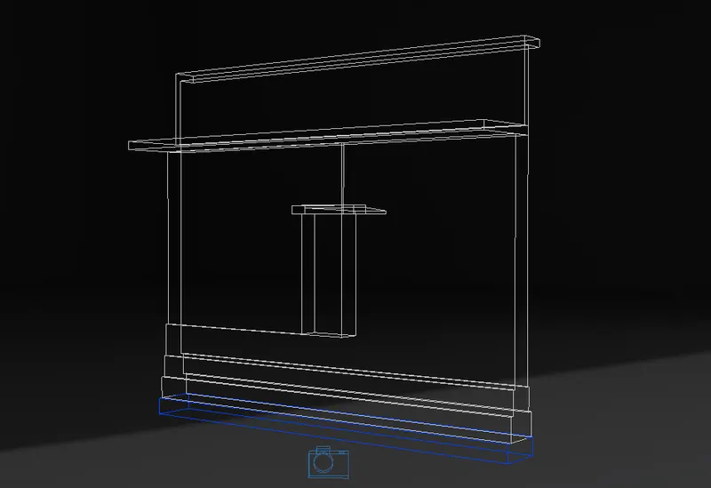
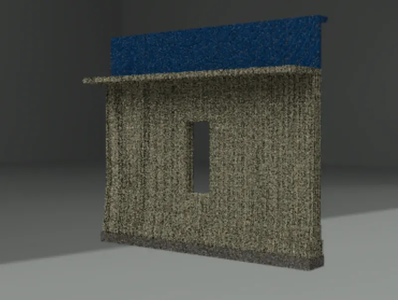
Creating 3D Isometric view of various structural elements in AutoCAD
1) AIM: Create a 3D Isometric View of the building.
INTRODUCTION: Create a 3D on the basis of given plan and elevation.
PROCEDURE:
- first open new autocad template file.
- go to insert> PDF import> challange 12.pdf
- now select the page you want to import.
- after import it in autocad , it is scaled as per scale factor.
- now change the drafting setting from 2D to 3D modeling.
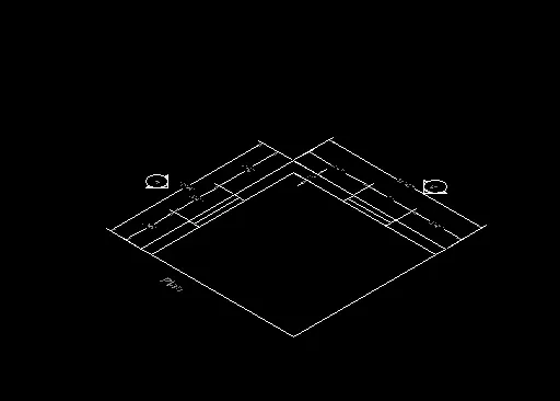
- command " Boundary" to create the region in 2D plan.
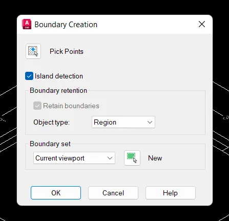
- now command " EXT" for extrude the wall of 10' height. for that select the region.
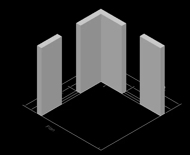
- using extrude and region command ,first created walls and window opening.
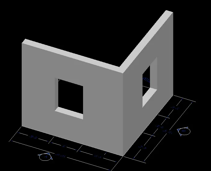
- now for making window in 3D, use 3DROTATE of plan of elevation and copy it and align with the opening of window.
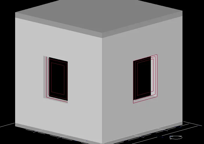
RESULT:
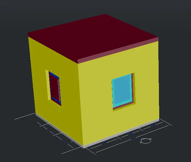
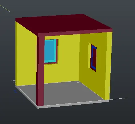
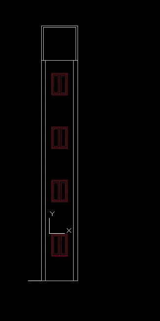
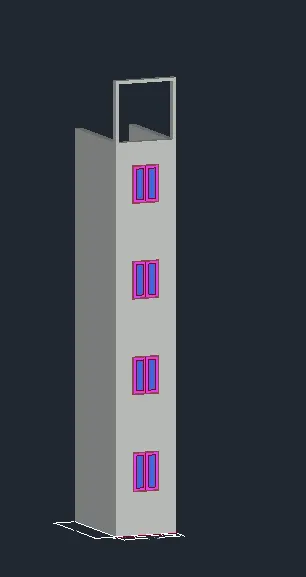
2) AIM: Create a 3D Isometric View of the building.
INTRODUCTION: Create a 3D on the basis of given plan and elevation.
PROCEDURE:
- first open new autocad template file.
- go to insert> PDF import> challange 12.pdf
- now select the page you want to import.
- after import it in autocad , it is scaled as per scale factor.
- now change the drafting setting from 2D to 3D modeling.
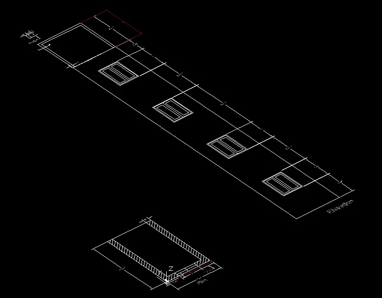
- command " Boundary" to create the region in 2D plan.
- now command " EXT" for extrude the wall of 8'8" height. for that select the region.
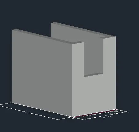
- using extrude and region command ,first created walls and window opening.
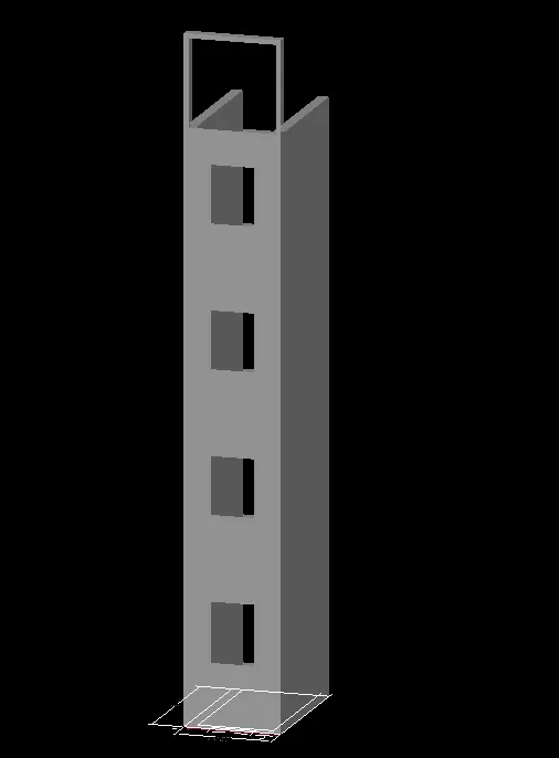
- now for making window in 3D, use 3DROTATE of plan of elevation and copy it and align with the opening of window.
RESULT:

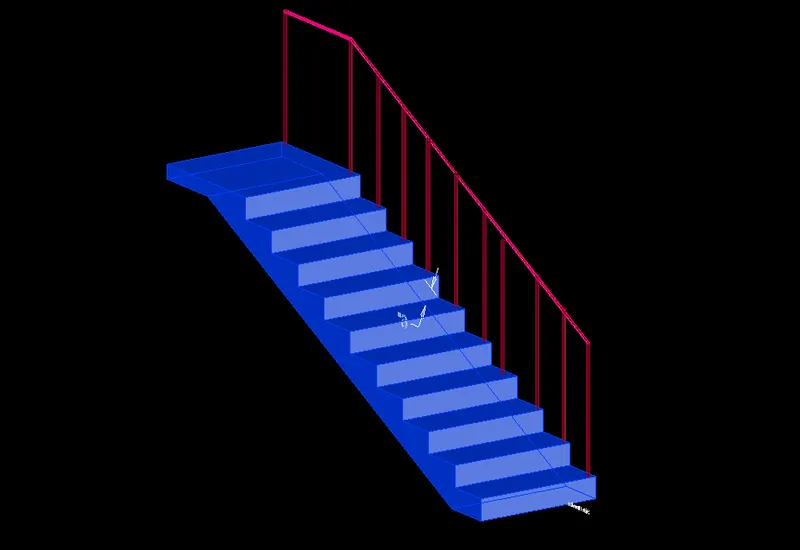
3) AIM: Create a 3D Isometric View of the stair with railing.
INTRODUCTION: Create a 3D on the basis of given plan and elevation.
PROCEDURE:
- first open new autocad template file.
- go to insert> PDF import> challange 12.pdf
- now select the page you want to import.
- after import it in autocad , it is scaled as per scale factor.
- now change the drafting setting from 2D to 3D modeling.
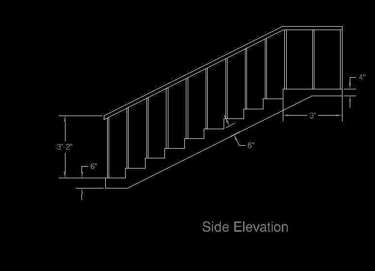
- now command " 3DROTATE" to rotate this 2d elevation along x axis so that it helps in extrude.
- command " region" and select the profile for extrusion with specific dimension.
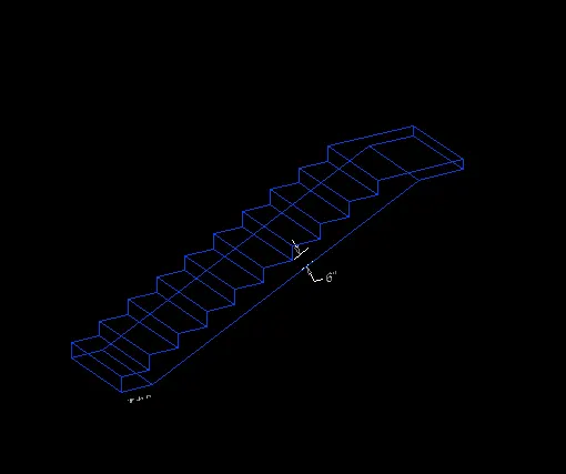
- for making railing, we use simple extrusion and for hand railing se loft extrude.
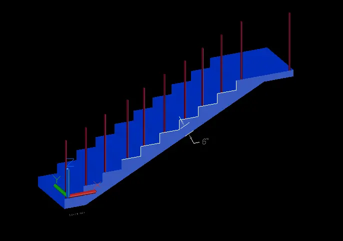
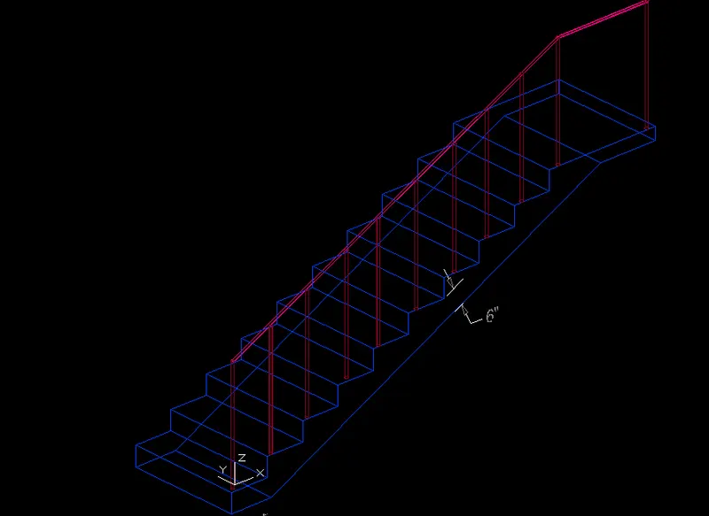
RESULT:
3) AIM:Create the 3D view of a Wall with spread footing
INTRODUCTION: Create a 3D on the basis of given plan and elevation.Create the Door opening only. Assume the size of the parpaet and the coping.
Also, create a rendered view of the model with materials as of your choice.
PROCEDURE:
- first open new autocad template file.
- go to insert> PDF import> challange 12.pdf
- now select the page you want to import.
- after import it in autocad , it is scaled as per scale factor.
- now change the drafting setting from 2D to 3D modeling.
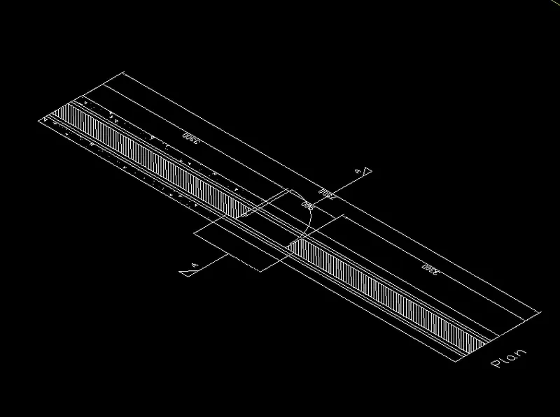
- First create wall of height 3300mm.
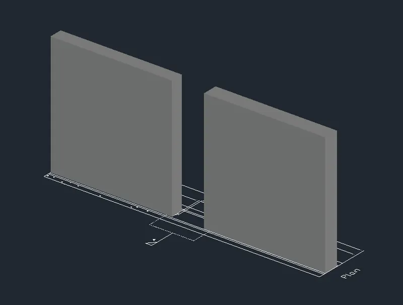
- now create strap footing of this wall.
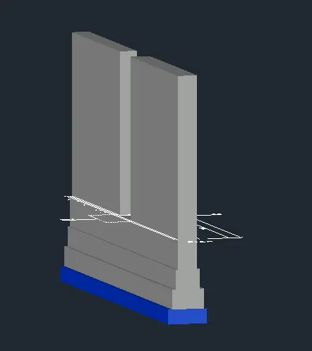
RESULT: