Creating 3D Isometric view of various structural elements in AutoCAD
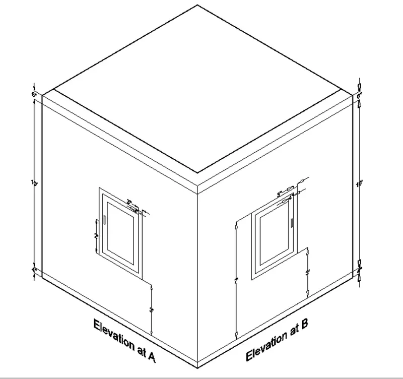
Create a 3D Isometric View of the building with plan and elevation given.
AIM:
To create a 3D isometric view of the building with the given plan and elevation by using the tools in AutoCAD.
PROCEDURE:
Step-1:
- Firstly, we have to draw the plan of the building.
- Select the command RECTANG and draw the rectangle as per the given dimension and also use the command PLINE to draw the width of the wall.
- Select the command LINE and complete the drawing of windows.
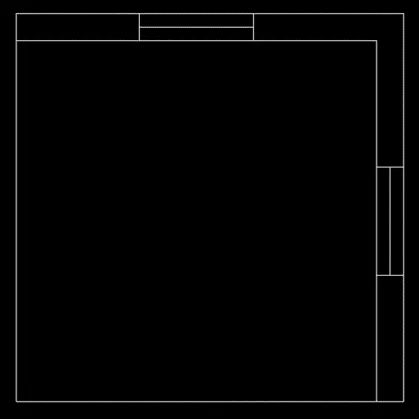
- Now we have to give dimensions and text for the plan.
- Select the command DIMLIN and give the required dimensions and select the command DTEXT for labelling the plan.
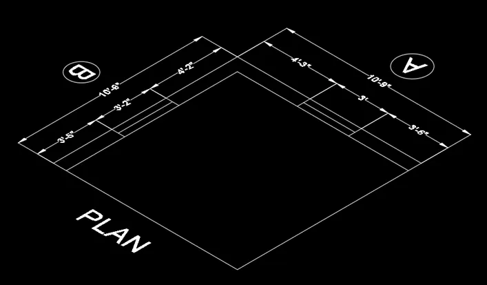
Step-2:
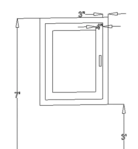
- After completing the plan of the building, now we have to draw the elevation A of the building.
- we have to draw the plan of the building again.
- Select the command RECTANG and draw the rectangle as per the given dimension and also use the command PLINE to draw the width of the wall.
- Use the command BOUNDARY to make the thickness of the walls as region or surface.
- Use the command EXTRUDE and elevate the plan to the required height.
- Select the command LINE and draw the beams for representation.
- Select the command UCS to place the UCS on the required face or easy working.
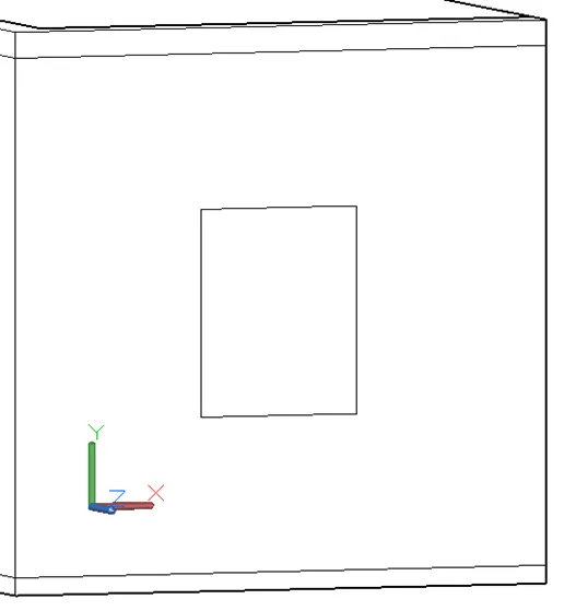
- Select the command RECTANG and draw the rectangle as per the given dimensions
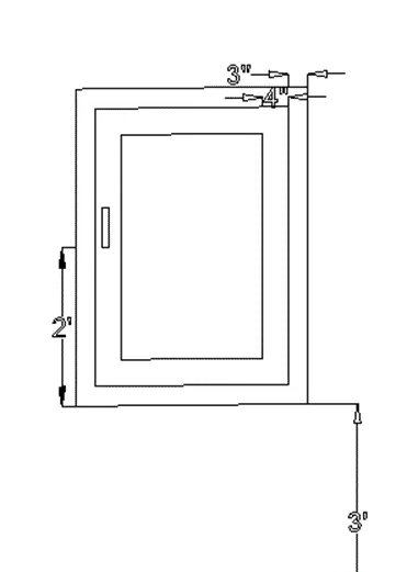
- Use the command OFFSET to draw the parallel rectangles.
- Select the command DIMLIN to give the required dimensions for the sketch and also use the command DTEXT for labelling the sketch.
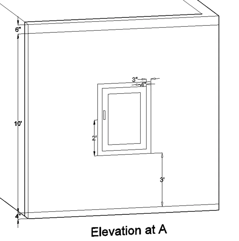
Step-3:
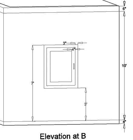
- After completing the drawing of elevation at A, now we have to draw the Elevation at B.
- Building elevation is already drawn, so we have to change the side of the building by using the command 3DORBIT.
- Select the command LINE and draw the beams for representation.
- Select the command UCS to place the UCS on the required face or easy working.
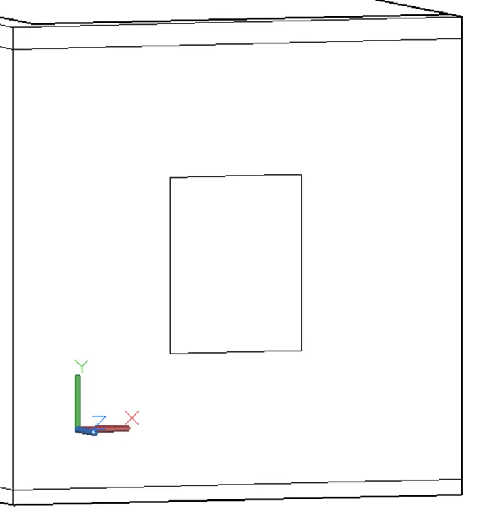
- Select the command RECTANG and draw the rectangle as per the given dimensions
- Use the command OFFSET to draw the parallel rectangles.
- Select the command DIMLIN to give the required dimensions for the sketch and also use the command DTEXT for labelling the sketch.
RESULT:
Create the 3D View of the Building Façade as given in the plan and elevation. Also, see the detail of the window.
AIM:
To create the 3D view of the building Façade with the given plan and elevation by using the tools in AutoCAD.
PROCEDURE:
Step-1:
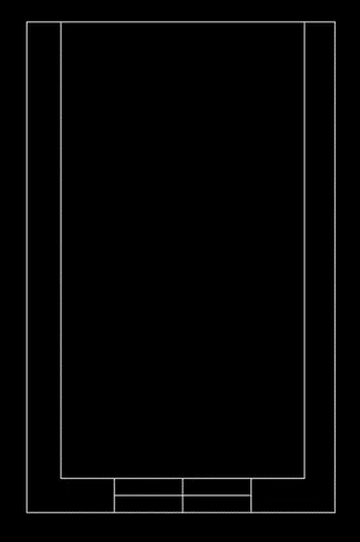
- Firstly, we have to draw the plan of the building.
- Select the command RECTANG and draw the rectangle as per the given dimension and also use the command PLINE to draw the width of the wall.
- Select the command LINE and complete the drawing of windows.
- Now we have to give dimensions and text for the plan.
- Select the command DIMLIN and give the required dimensions and select the command DTEXT for labelling the plan.
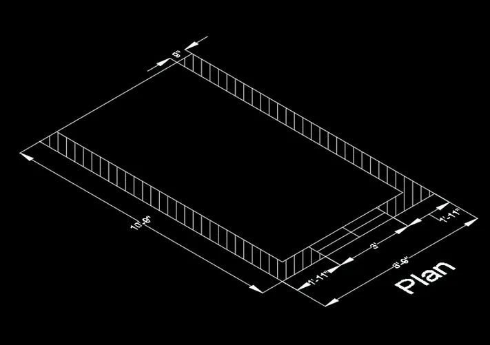
- After completing the sketch of the plan, now we have to draw the detailed sketch of window as per the given dimensions.
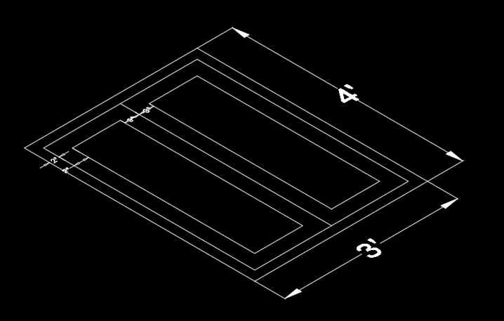
Step-2:
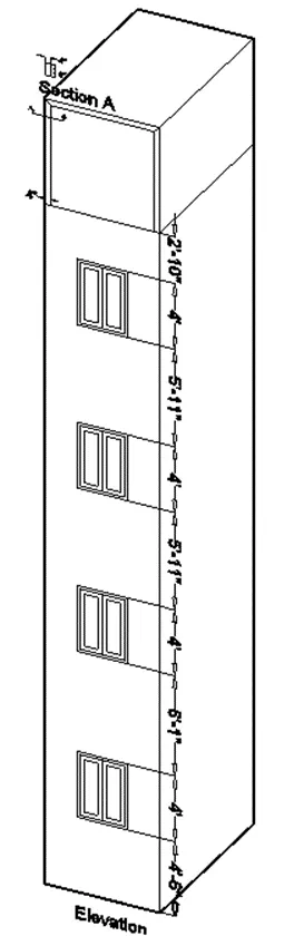
- After completing the plan of the building, now we have to draw the elevation of the building.
- we have to draw the plan of the building again.
- Select the command RECTANG and draw the rectangle as per the given dimension and also use the command PLINE to draw the width of the wall.
- Use the command BOUNDARY to make the thickness of the walls as region or surface.
- Use the command EXTRUDE and elevate the plan to the required height.
- Select the command UCS to place the UCS on the required face or easy working.
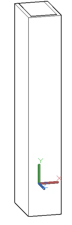
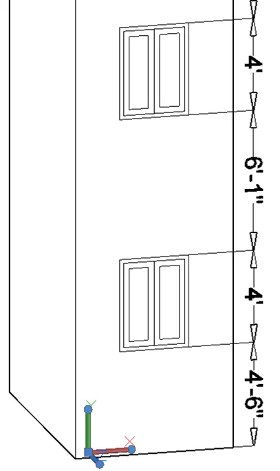
- After completing the elevation of the building, now we have to place the window on the front face of the building.
- Now we have to rotate the window in 900 in vertical direction by using the command 3DROTATE by using the x-axis as rotation.
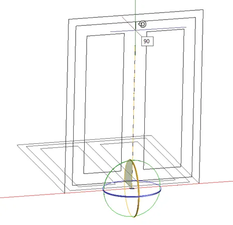
- After rotation of the window, we have to place the window on the front face of the building by using the command MOVE.
- Select the command COPY and place the window in required places.
- Select the command DIMLIN to give the required dimensions for the sketch and also use the command DTEXT for labelling the sketch.
Step-3:
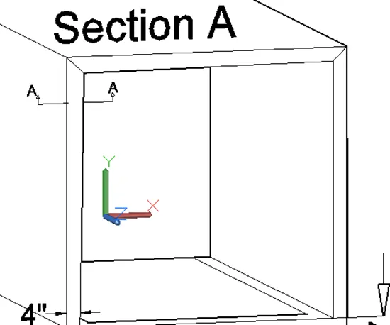
- After completing the elevation of the building, now we have the draw the top floor of the building.
- Select the command PLINE to draw the outer side of the wall and also select the command OFFSET to draw the parallel inner side of the wall or thickness of the wall.
- Use the command BOUNDARY to make the thickness of the walls as region or surface.
- Use the command EXTRUDE to extend the thickness of wall in horizontal direction.
- Select the command UCS to place the UCS on the required face or easy working.
- Select the command 3DFACE to create the surface on the working face of the sketch.
- Select the command DIMLIN to give the required dimensions for the sketch and also use the command DTEXT for labelling the sketch.
RESULT:
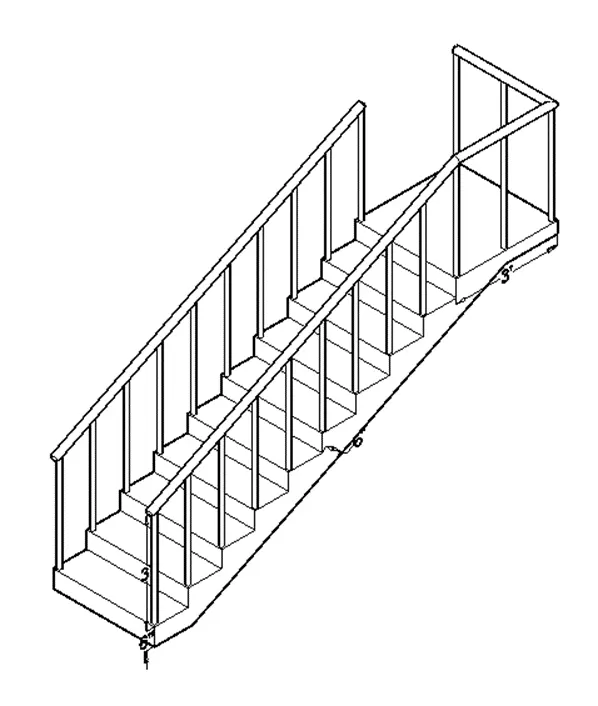
Create the isometric 3d view of a stair with railing as shown in the plan and elevation. Assume the size of the balustrades and the hand rails.
AIM:
To create the isometric view of a stair with railing by the given plan and elevation by using the tools in AutoCAD.
PROCEDURE:
Step-1:
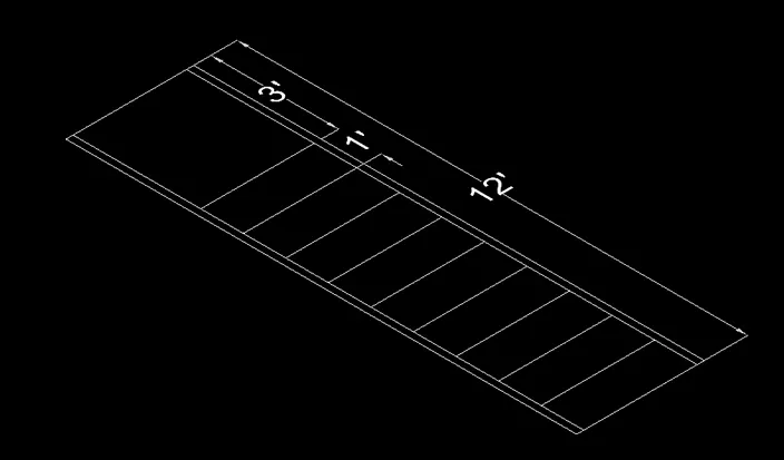
- Firstly, we have to draw the plan of the staircase by using the command RECTANG to draw the rectangle as per the dimension.
- Select the command LINE to draw the line to represent the handrail and draw one step at required length.
- select the command OFFSET to draw the lines of steps.
- Select the command DIMLIN to give the required dimensions for the sketch and also use the command DTEXT for labelling the sketch.
Step-2:
- After completing the plan of the staircase, now we have we to draw the side view of the stair by using the command PLINE.
- After completing the drawing of side view, we have to create it as the surface or region by using the command BOUNDARY.
- Now we have to rotate the stair in 900 in vertical direction by using the command 3DROTATE by using the x-axis as rotation.
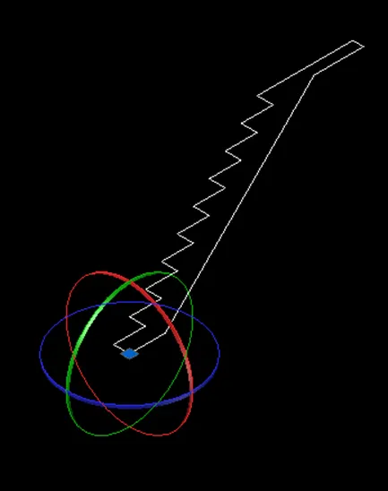
- After completing the rotation of stair, now we have to extrude the staircase by using the command EXTRUDE as per the dimension.
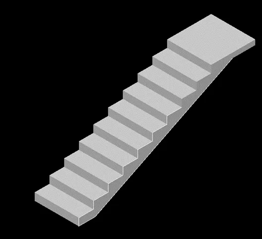
- Now select the command UCS to place the UCS on required face for easy working.
- Select the command CIRCLE to draw the circle on the working face.
- To draw the balustrade, use the command EXTRUDE to extend the circle up to required height.
- Then select the command COPY to place the balustrade in required positions.
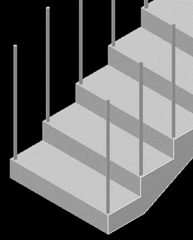
- After completing the placing of balustrade, now we have to draw the hand rail.
- Select the command PLINE and draw the line connecting top of each balustrade we have drawn.
- To draw the hand rail, use the command SWEEP to draw the circles around the polyline and the polyline taken as axis.
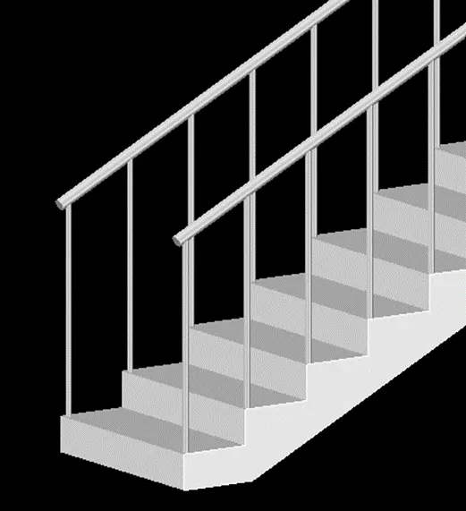
- Select the command DIMLIN to give the required dimensions for the sketch and also use the command DTEXT for labelling the sketch.
RESULT:
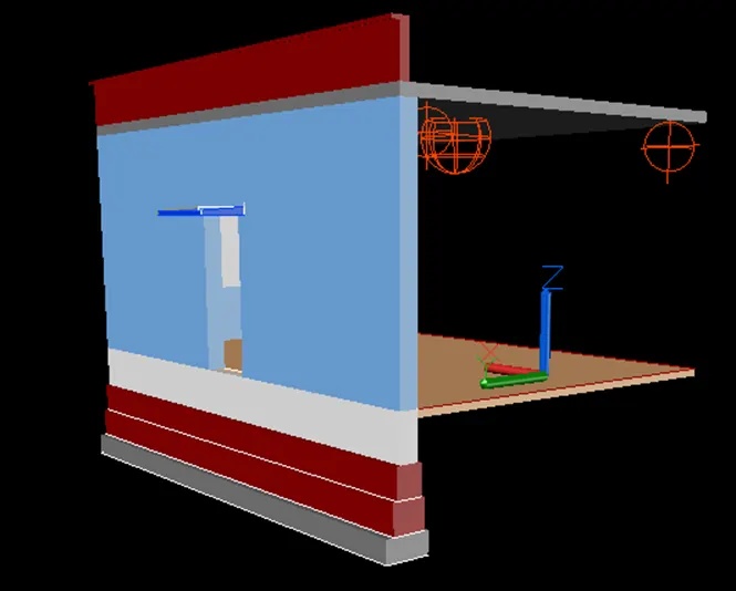
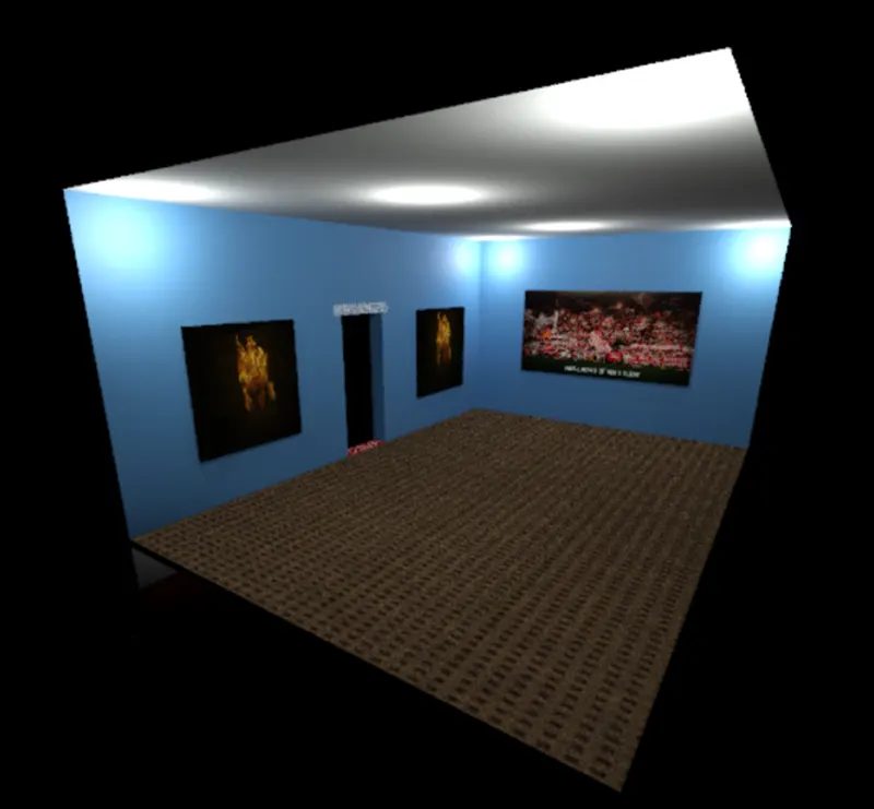
Create the 3D view of a Wall with spread footing. Create the Door opening only. Assume the size of the parapet and the coping. See the plans and elevation for the details. Also, create a rendered view of the model with materials as of your choice.
AIM:
To create the 3D view of a wall with spread footing and the door opening by assuming the size of parapet and the coping with the given plan and elevation by using the tools in AutoCAD.
PROCEDURE:
Step-1:
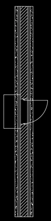
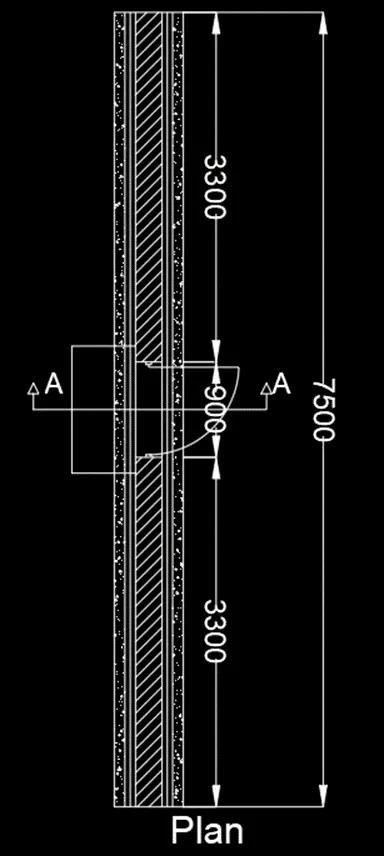
- Firstly, we have to draw the plan of wall with spread footing.
- Select the command LINE to draws the rectangle to complete the drawing of wall as per the dimension.
- Use the command OFFSET to draw the parallel lines to complete the drawing of wall, beam and footing.
- We use the command LINE and command CIRCLE to complete the sketch of door.
- Select the command HATCH for highlighting the brick work and concrete work
- Select the command DIMLIN to give the required dimensions for the sketch and also use the command DTEXT for labelling the sketch.
Step-2:
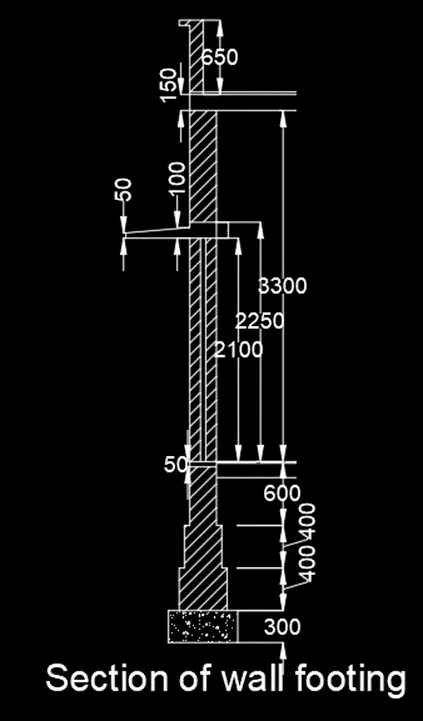
- After complete the sketch of plan, now we have to draw the section AA of the wall.
- Select the command LINE to complete the drawing of footing, plinth beam, window, sunshade, floor, slab and parapet wall.
- Use the command OFFSET to draw the parallel lines and complete the drawing of section AA.
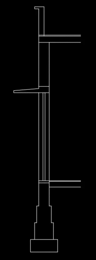
- Select the command HATCH for highlighting the brick work and concrete work
- Select the command DIMLIN to give the required dimensions for the sketch and also use the command DTEXT for labelling the sketch.
Step-3:
- After completing the plan and sectional view of the wall with spread footing, now we have to draw the isometric view for the wall.
- Select the command RECTANG to draw the rectangle for representing the footing.
- Select the command BOUNDARY to make the rectangle as a surface and use the command EXTRUDE to elevate the rectangle up to specified height.
- Select the command UCS and place the UCS on the top face of the footing.
- Use the command PLINE to draw the rectangle on the top face and select the command BOUNDARY to make the rectangle as a surface.
- Again, select the command EXTRUDE to elevate the rectangle to specified height.
- Continue the above process of steps of footing up to floor height.
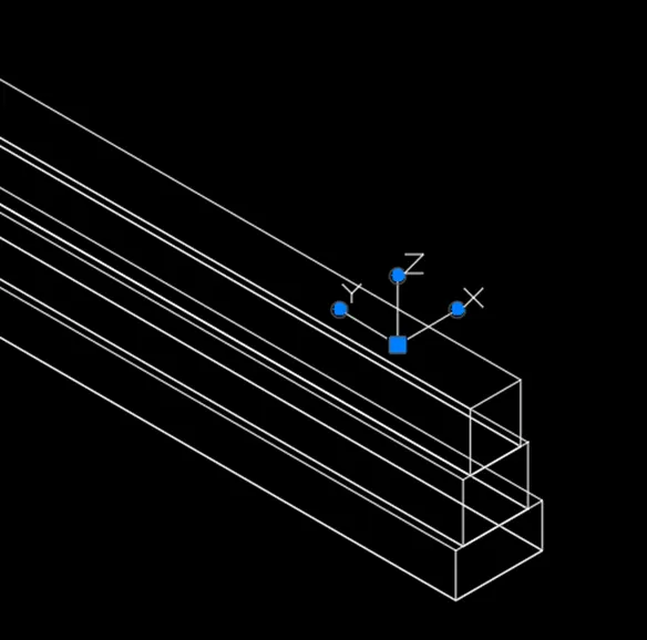
- After completing the sketch of footing and beam up to floor height, now we have to draw the wall and floor.
- Select the command UCS and place the UCS on the top face of the plinth beam.
- Use the command PLINE to draw the rectangle on the top face and select the command BOUNDARY to make the rectangle as a surface.
- Select the command EXTRUDE to elevate the rectangle to specified height to represent as wall.
- After we have to place the UCS on the side face of the wall and draw the rectangle by using the command RECTANG to draw the length of floor.
- Select the command BOUNDARY to make the floor as a surface and use the command EXTRUDE to draw the thickness of floor.
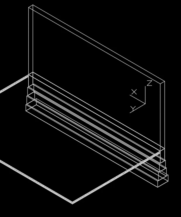
- Again, place the UCS on the side face of the wall and draw the door by using the command PLINE and make the door as a surface by using the command REGION.
- Select the command EXTRUDE to extend the door for its thickness and select the command SUBTRACT to create the space for door opening.
- Place the UCS on the top face of the wall and draw the rectangle for slab y using the command RECTANG and make t as a region by using the command REGION.
- Use the command EXTRUDE to elevate the slab up to its thickness.
- By using the same procedure for complete the sketch of lintel beam, sunshade, parapet wall and coping.
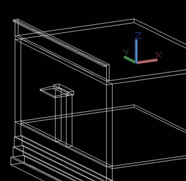
- After completing the sketch of isometric view of the wall and footing, now we have to create a render view for the sketch.
- Firstly, we have to create random views for the sketch and then we have to place the camera and point lights for lighting.
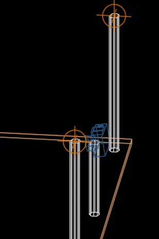
- Place the UCS on the floor and select the command CIRCLE and select the command EXTRUDE to elevate the circles at a specified height for camera and point light.
- Use the command COPY to place the elevated circles at required places.
- Select the command CAMERA and command POINTLIGHT place them on the required elevated circles.
- Use the command PROPERTIES to give the colours for the walls, footing, plinth beam, flooring, slab, parapet wall, sunshade.
- Use the command WEBLIGHT and place the light on the elevated circles.
- Select the command ERASE to remove the elevated circles.
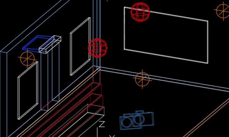
- After placing the lights over the sketch, now we have to give the materials for the sketch.
- Use the command MAT and select the AutoCAD library and select the wall painting and flooring for complete the selection of materials for the sketch.
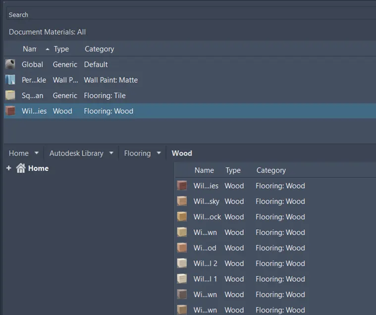
- After completing the selection of materials, we have to insert the paintings for decoration.
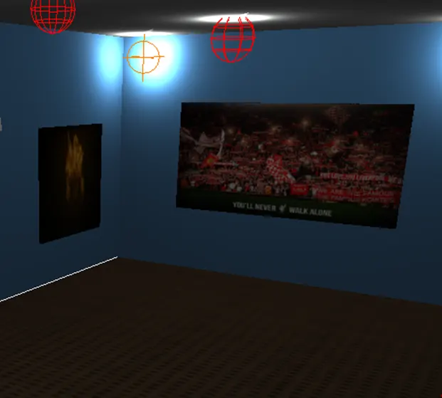
- Select the command MAT and select the option new generic material and select the image from the system and place them.
- For adjust the image we can use the command MATERIAL MAPING to adjust the image.
RESULT: