Creating 3D Isometric view of various structural elements in AutoCAD
1 aim:
Create a 3D Isometric View of the building with plan and elevation given.
tools were used :rec
offset
mat browser
extrude
press pull
union
intersect
3d rotate
dim
region
boundary
procedure:create the room size using rectangle and then extrude or presspull them , as per the required dim given there
already i have give some space for the window
then i make rec over the window space
and extrude it for some dim
rest of the solid we need to subract them to made the void for window
atlast some mat bhrowser added over the solid 3d model for the further clarification ..
finally 3d model made through the 3d modelling interface and 3d comments to do that......
2.aim:
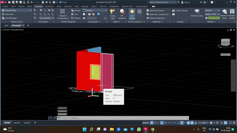
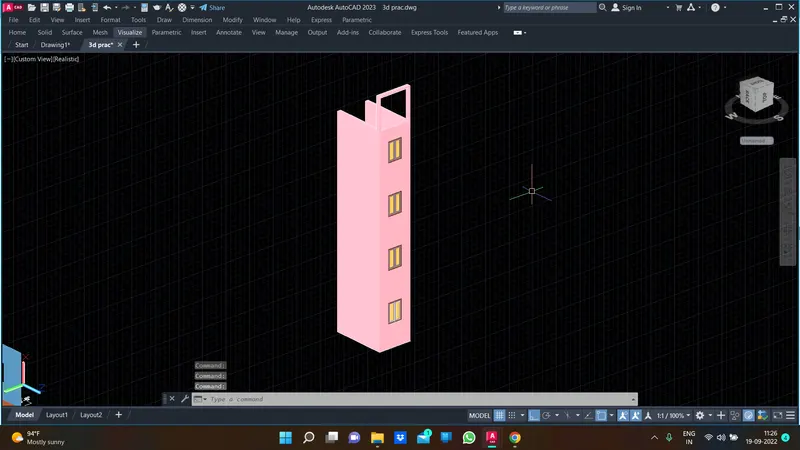
Create the 3D View of the Building Façade as given in the plan and elevation. Also, see the detail of the window.
tools were used :
offset
mat browser
extrude
press pull
union
intersect
3d rotate
dim
region
boundary
procedure :
need to create the 3d view of the building
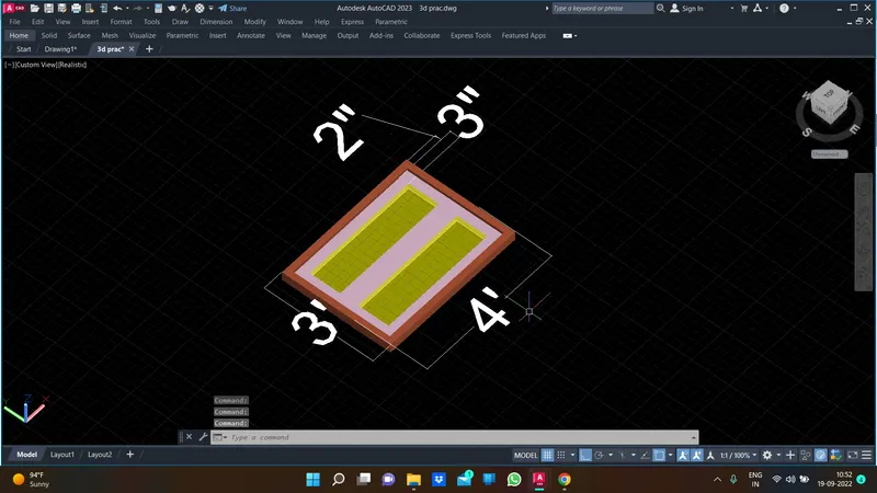
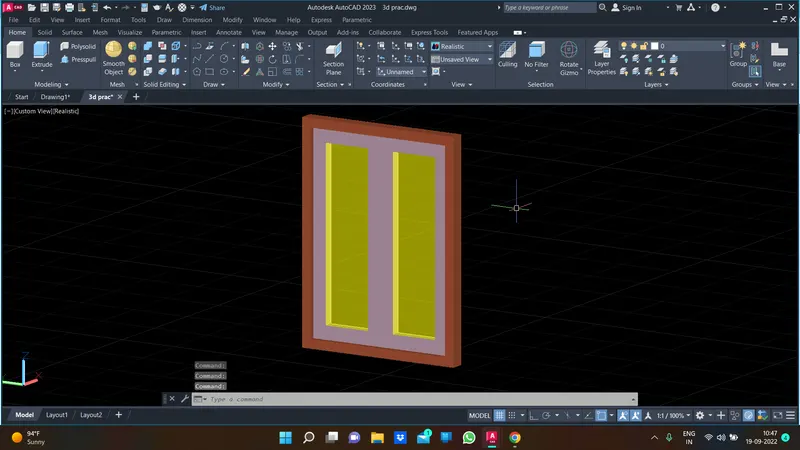
first need to make window for building make the rec and offset it
region is insert and make extrude for the win panel
and open the mat browser to apply the material for the particular window
and glasss are provided for the window panel
next just make the rec and extrude it and then fix the rest window in the particular area to make the building
result:
3.aim:
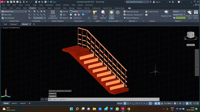
Create the ismoteric 3d view of a stair with railing as shown in the plan and elevation. Assume the size of the balustrades and the hand rails.
tools were used :
offset
mat browser
extrude
press pull
union
intersect
3d rotate
dim
region
boundary
sweep
procedure :
draw the 2d drawing for the stair whuch is elevation and section
need the section drawing to extrude the surface
first extrude the section drawing
and make the balustrsdes and hand railing for our assumption
draw the circle and draw the line over the middle of the balustrades
sweep the circle click the path to create sweep as a hand railing
finally appy some material to show the stair realistic and aesthetic
result :
4.aim:
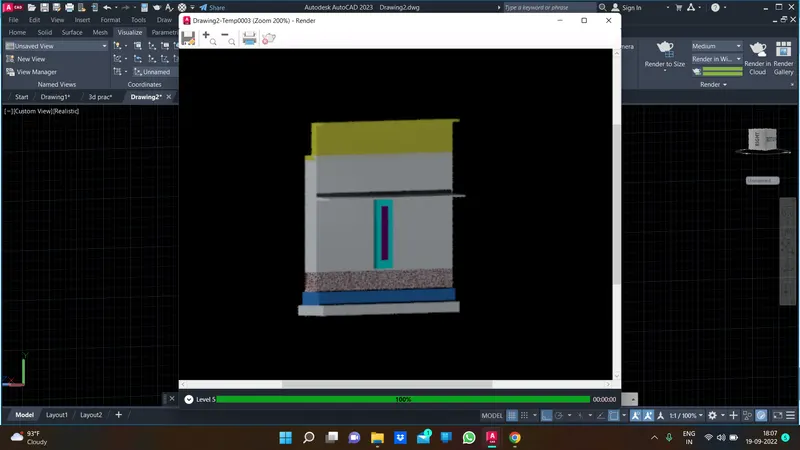
Create the 3D view of a Wall with spread footing . Create the Door opening only. Assume the size of the parpaet and the coping. See the plans and elevation for the details. Also, create a rendered view of the model with materials as of your choice.
tools were used :
offset
mat browser
extrude
press pull
union
intersect
3d rotate
dim
region
rr - rendering
boundary
procedure :
create the section of the wall spread footing
extrude it to show the 3d view
make the door for the wall
create the rec and extrude it to made the door and along with door
glasses are made by the help of mat browser
and finaly we need to render it however type rr to render the element which is drew on the 3d interfce
result: