Creating 3D Isometric view of various structural elements in AutoCAD
AIM
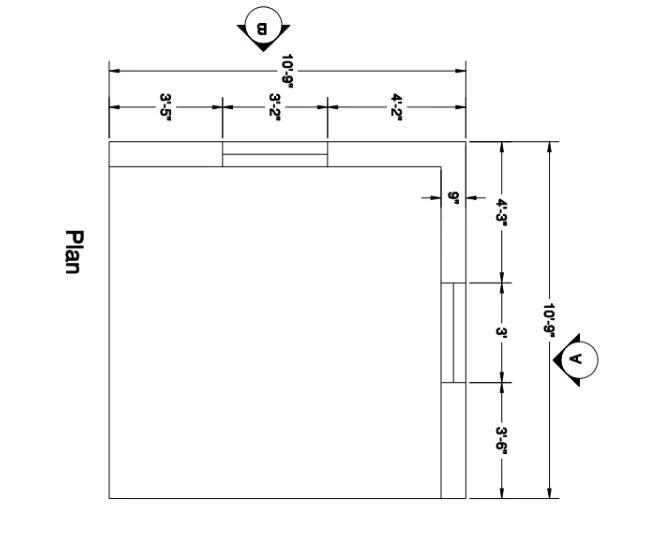
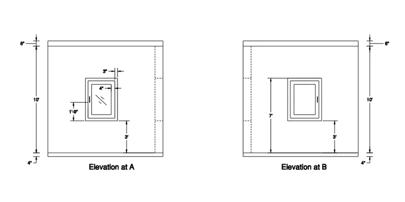
To create a 3D Isometric View of the building with plan and elevation given
INTRODUCTION
Here we are using 3D modeling in AutoCAD
Tools used in 2d modeling are also used in 3D modeling
The special tools used in 3D modeling are
3DROTATE
3DORBIT etc..
PROCEDURE
Step 1:Draw the plan and elevation using line tool
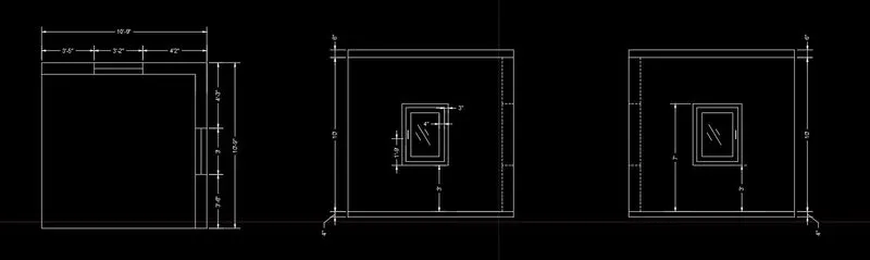
Step 2:Change the workspace into 3D modeling
Step 3:Using boundary option select the region to draw wall
Step 4:Enter extrude command, select the area
Enter the value 10’
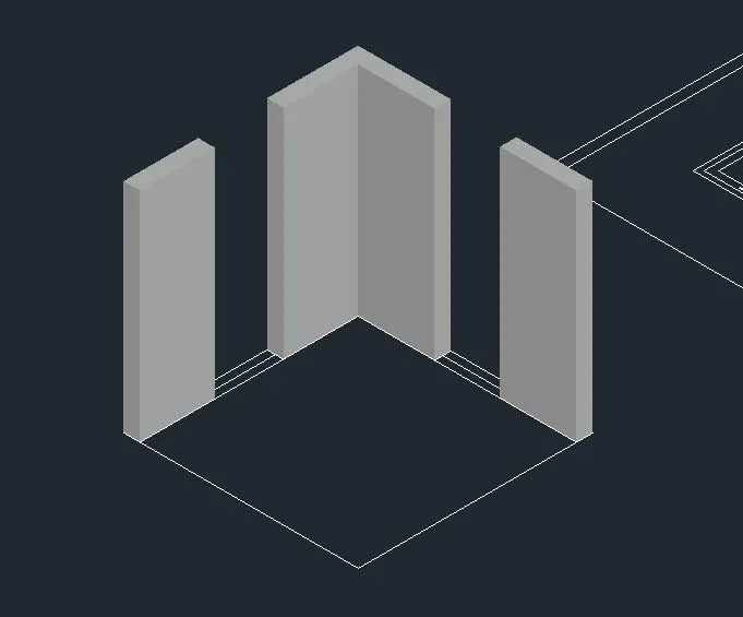
Step 5: Using 3DROTATE command rotate the elevation
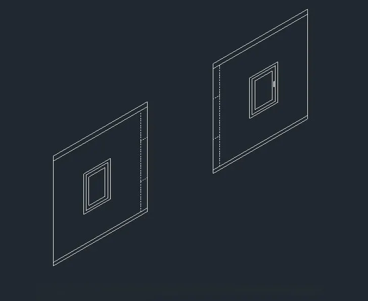
Step 6:Draw the windows
Select the area using boundary command
Delete unwanted area using subtract
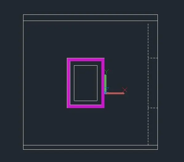
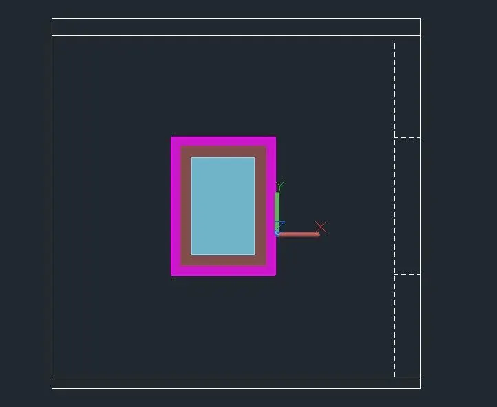
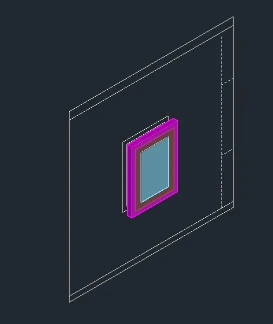
Step 7:Rotate and copy the window to other side
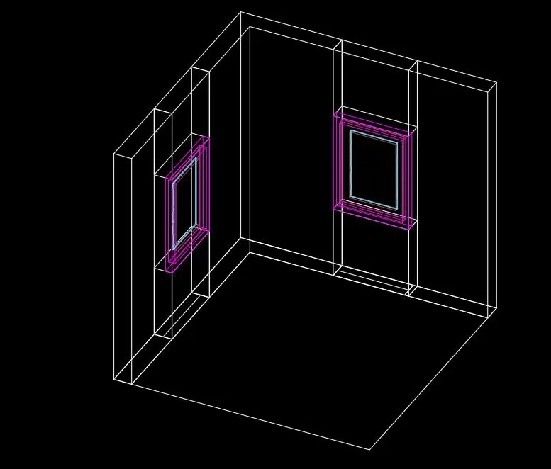
Step 8:Using rectangle tool draw the rectangle on top
Enter boundary command and select the region

Step 9:Copy the region to lower side
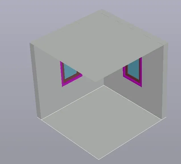
Step 10:Extrude 6” on top and 4” on bottom
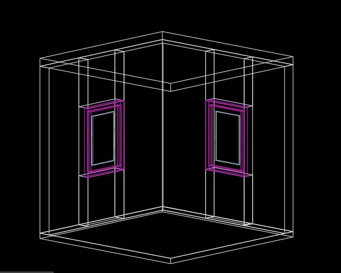
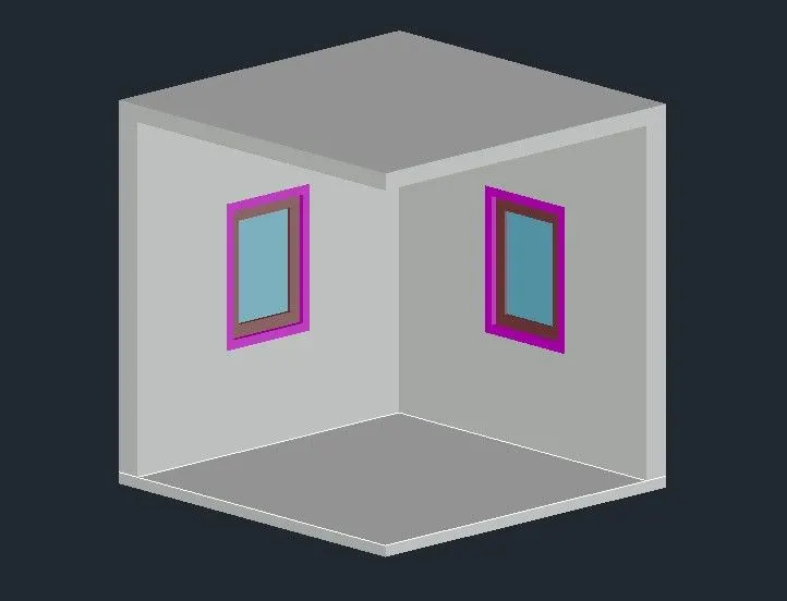
RESULT
AIM
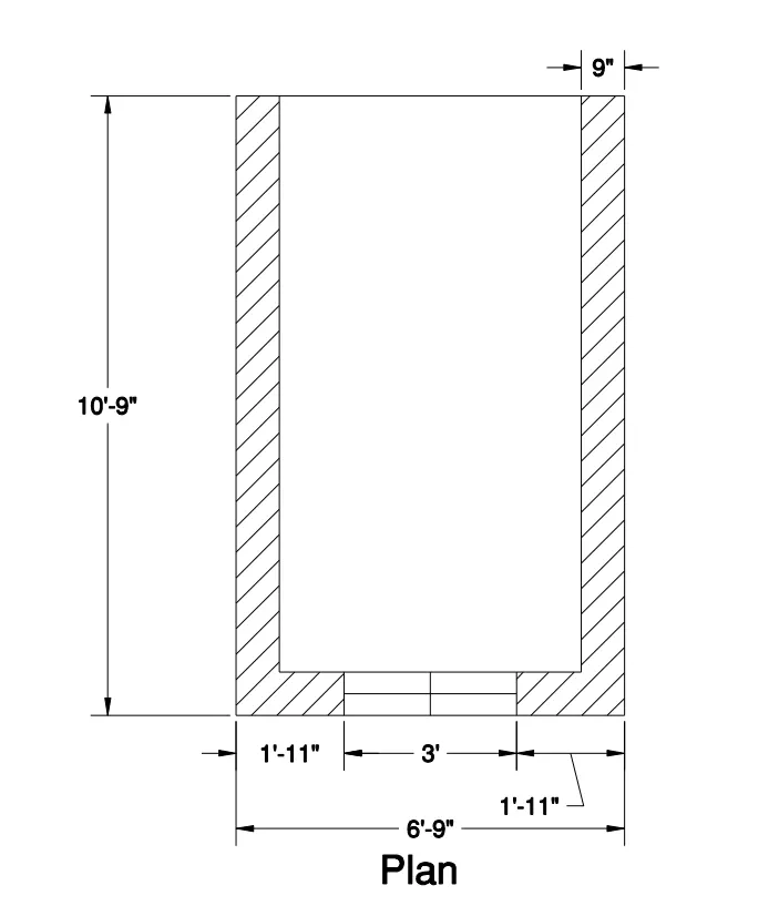
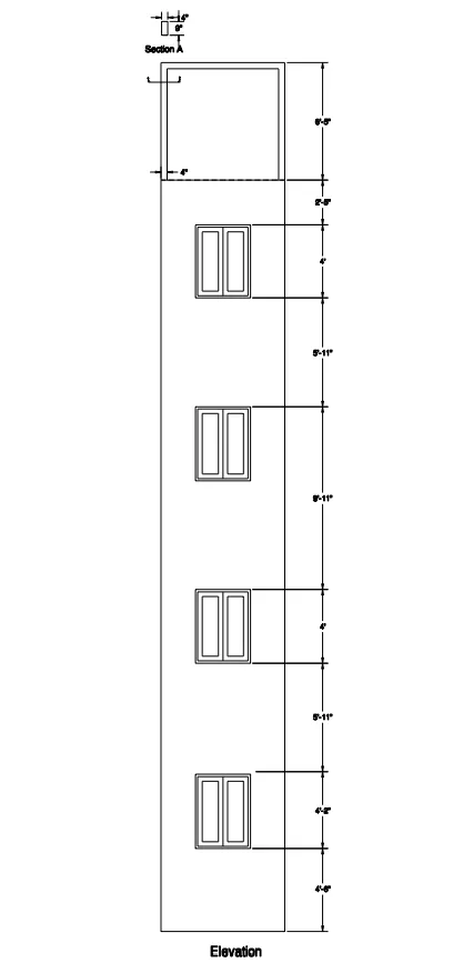
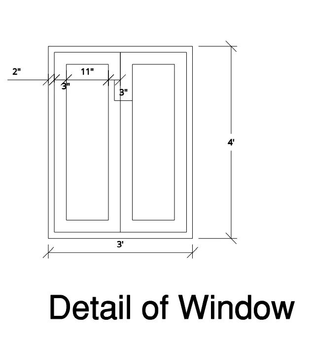
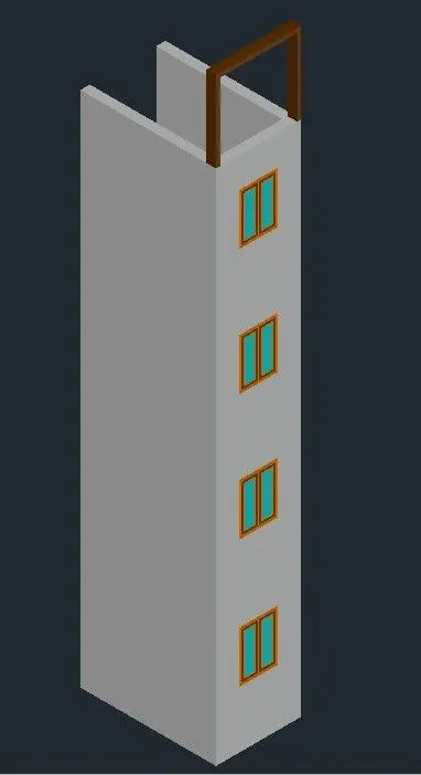
To create the 3D View of the Building Façade as given in the plan and elevation. Also, see the detail of the window
INTRODUCTION
Here we are using 3D modeling in AutoCAD
Tools used in 2d modeling are also used in 3D modeling
The special tools used in 3D modeling are
3DROTATE
3DORBIT etc..
PROCEDURE
Step 1:Draw the plan,elevation and window using line tool
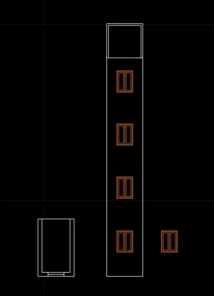
Step 2:Change the workspace into 3D modeling
Step 3:Rotate the elevation and window plan
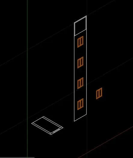
Step 4:Using boundary option select the region to draw wall
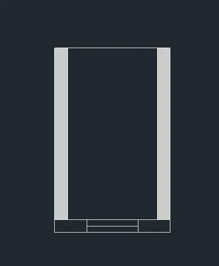
Step 5:Enter extrude command, select the area
Enter the value
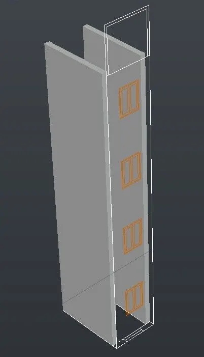
Step 6:Enter region command select the elevation
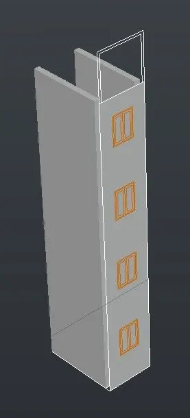
Step 7:Draw the rectangle on window on elevation
Using subtract command subtract the window area
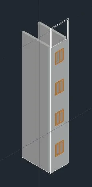
Step 8:extrude the wall thickness of elevation
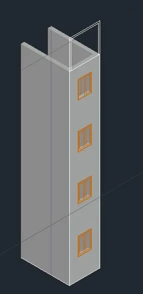
Step 9:Draw the windows using boundary command
Subtract the unwanted area
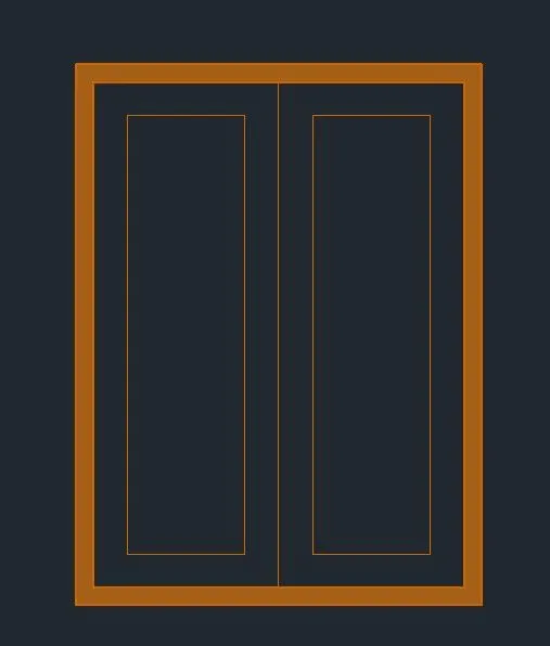
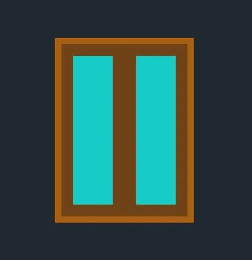
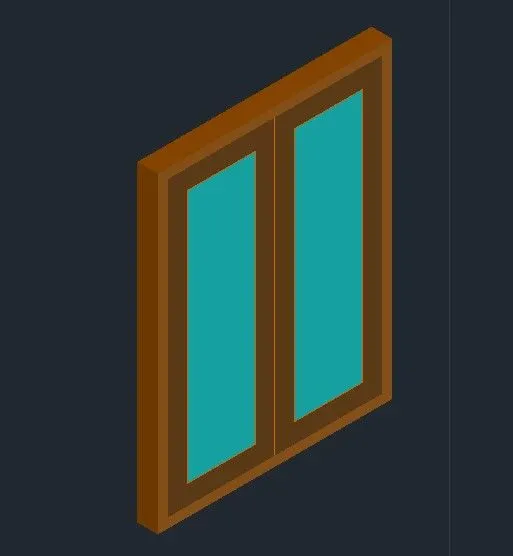
Step 10:Place the windows on the window area using copy command
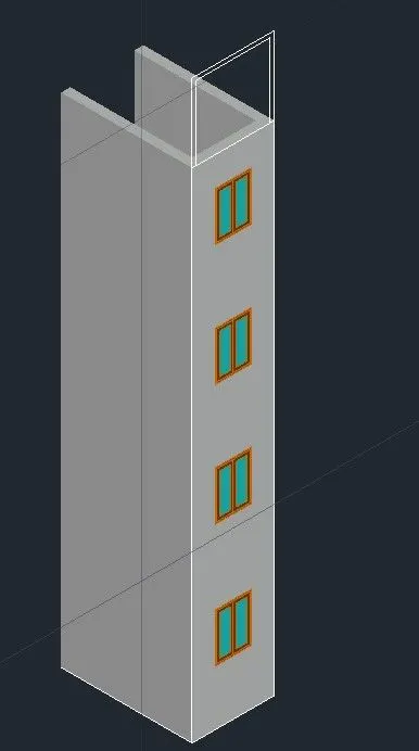
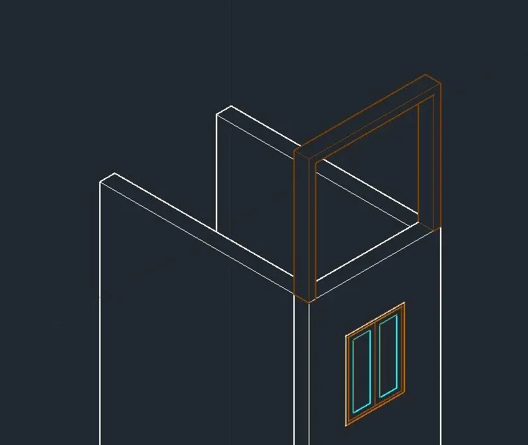
Step 11:Draw the element on the top
By region command and extrude option
RESULT
AIM
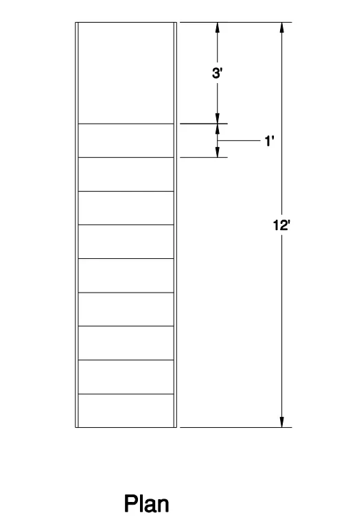
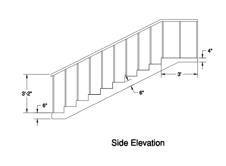
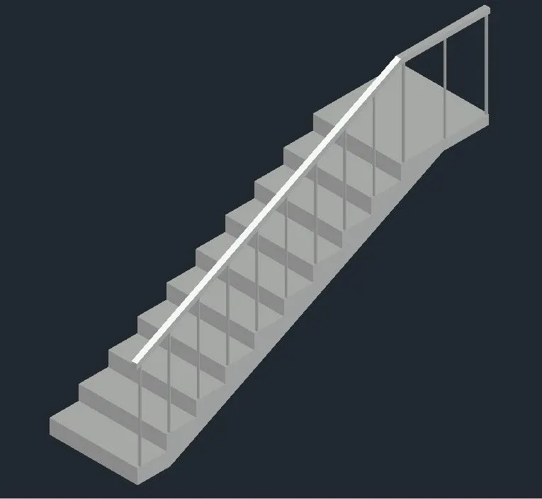
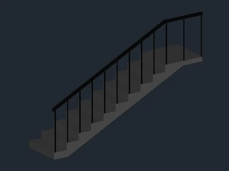
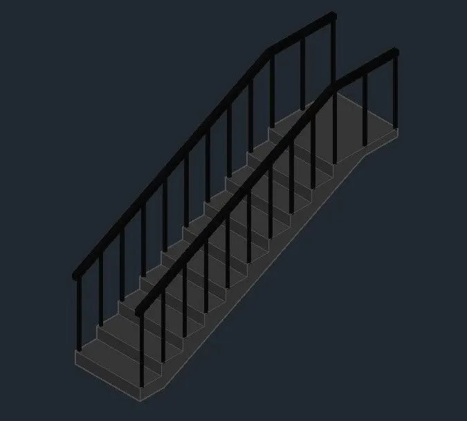
To create the isometric 3d view of a stair with railing as shown in the plan and elevation. Assume the size of the balustrades and the handrails.
INTRODUCTION
Here we are using 3D modeling in AutoCAD
Tools used in 2d modeling are also used in 3D modeling
The special tools used in 3D modeling are
3DROTATE
3DORBIT etc..
PROCEDURE
Step 1:Draw the plan of the staircase using line tool
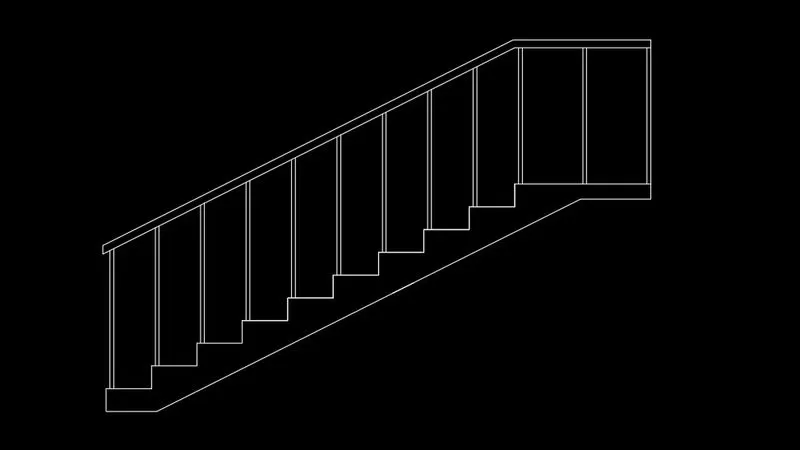
Step 2:Change the workspace into 3D modeling
Step 3:Rotate the plan
Step 4:Using boundary option select the region to draw the staircase
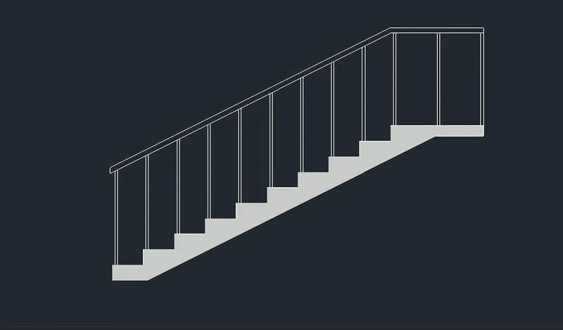
Step 5:Enter extrude command, select the area
Enter the value 3”
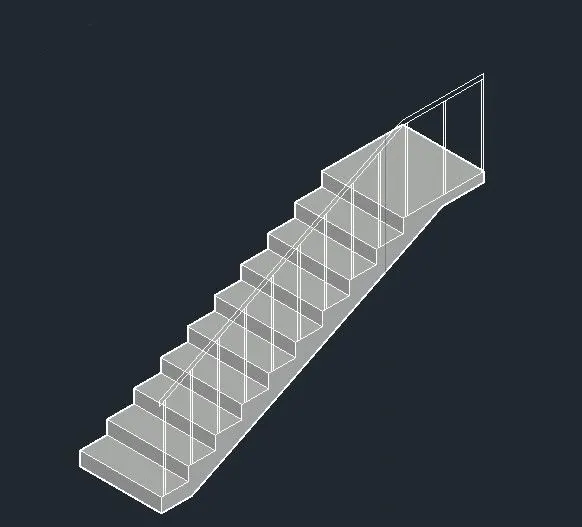
Step 6:Draw the handrail using circle command
Extrude the circle
Enter the vale 3’-2”
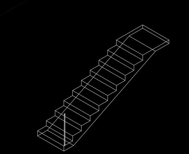
Step 7:Copy the handrail, using the plan place it on th position
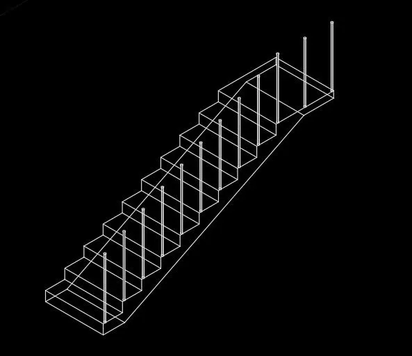
Step 8: Select the balustrade area using boundary option
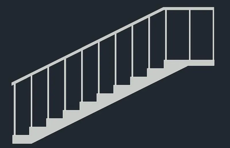
Step 9:Extrude the balustrade
Step 10:Provide materials to the elements
Step 11:Copy the handrail and balustrade
RESULT
AIM
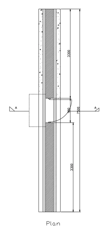
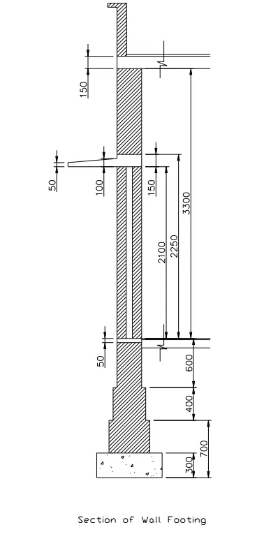
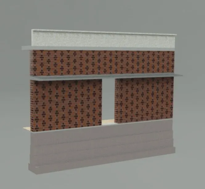
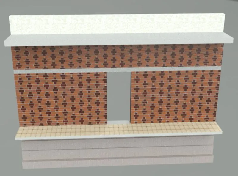
To create the 3D view of a Wall with spread footing . Create the Door opening only. Assume the size of the parpaet and the coping. See the plans and elevation for the details. Also, create a rendered view of the model with materials as of your choice
INTRODUCTION
Here we are using 3D modeling in AutoCAD
Tools used in 2d modeling are also used in 3D modeling
The special tools used in 3D modeling are
3DROTATE
3DORBIT etc..
PROCEDURE
Step 1:Draw the plan of the section using line tool
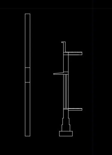
Step 2:Change the workspace into 3D modeling
Step 3:Rotate the plan
Step 4:Using boundary option select the region to draw the wall and other elements
Provide different layer for different elements
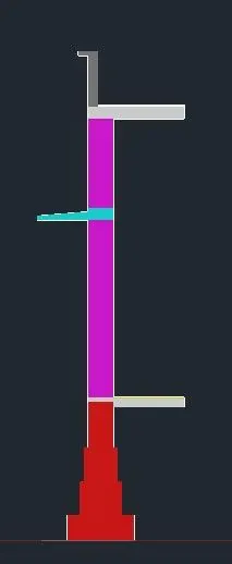
Step 5:Extrude the elements using the dimension in plan
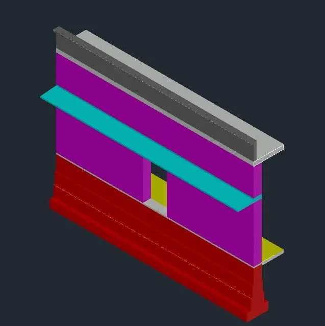
Step 6:Provide material
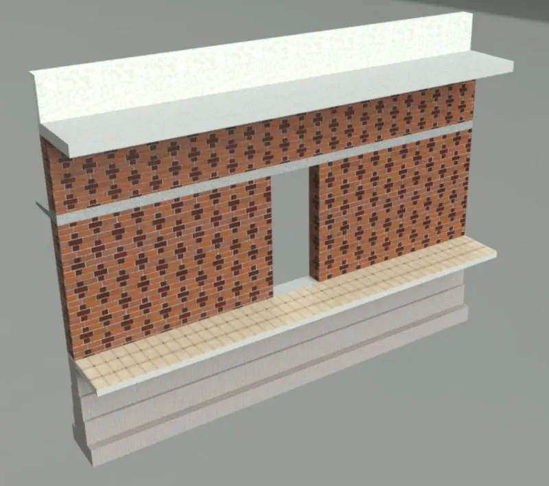
Step 7:Select camera option and set the camera angle
Save the camera view
Step 8:Select visualize in ribbon and select the render option
Enable environment
Step 9:Render the window
Save the file
RESULT
RESULT
Here we studied about 3D modeling using AutoCAD