Creating 3D Isometric view of various structural elements in AutoCAD
AIM : To Creating 3D Isometric view of various structural elements in AutoCAD.
INTRODUCTION: AutoCAD offers various tools to perform different tasks. The various tools which are used for drafting in this project are briefly described here. These draw tools include: - line,Construction line,rectangle,polygon,polyline,circle,elepse etc.similarly we can draw the tasks as in the 3dimension view which is known as 3d drafting. this includes also various commands were used in 3d derafting. that are based on the different type of models whcich are
1.Wireframe models
2.Surface models
3.solid models
Commands used in 3d :
1.3d orbit - to view the model in the 360 degree view .
2.3d face - to selct the face as the solid by clicking the corners.
3.Hide - this is thecommand used to convert the 2d wireframe to hidden
4.Shade - this is thecommand used to convert the 2d wireframe to shaded.
5.surface tab 1& 2- these are help to smoothen the object by creating the lines in between. we can also adjust the no.of lines. or faes.
6.Rule surf - to connect two objects or lines by selecting both defining curves.
7.Edge surf - to connect four objects or lines .
8.Rev surf - to revolve the surface.
9.Tabulated surface - this command is use to create the lines which are in liked path curve based on the height of object.
10.box - to create the box having length,width,height.
11.cylinder - to create the cylinder.
12.sphere - to create a sphere.
13.polysolid - it is the solid model by creating with contineuty of the lines.
14.wedge
15.cone
16.pyramid - to draw the pyramid.
17.torus
18.extrude - it a command to give hieght to the object in the z-axis.
19.presspull - it is a command like extend, that is help to pulloff the object in any direction.
20.revolve - the command use to revolve by 360 degree with referance or with out.
21.sweep - the command used to connect the two solids.
22.Loft - the command used to connect the two or more objects make to one.
23.union - the command used to bind the two objects or solids as one.
24.subtract - its used to eliminate the objects present in a solid.
25.intersect - its used to cut the intersected part of solid.
26.mass properties - Masprop - it shows all the data about the object licke height,width,mass,moment of inerrtia,etc.
27.Face tres - to smoothen the object. the value is max - 10.
28.solidedit - to edit the solids
29.extract edges - it converts a object in to 2d wireframe.(Xedges)
30.fillet edge
31.chamfer edge
32.3D rotate
33.3D mirror
34.3D move
35.3D array
36.Align - it use to set the object on the any plane through the face of object.
37.slice - it is a command like break to help the divide of solid in to two parts.
38.section- is use to coy the section from the solids.
39.Materials browser
40.Rendering- RR is the commad to render the inserted materials.
1A.
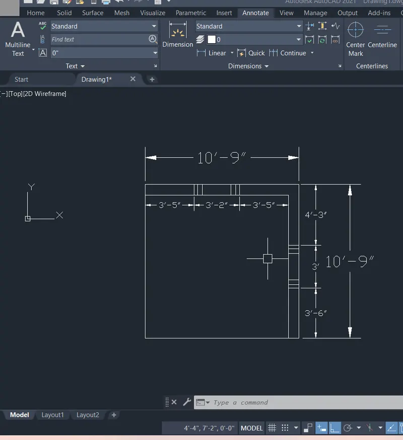
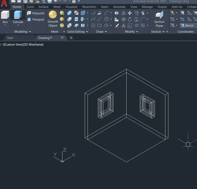
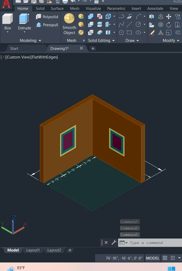
AIM : To Create a 3D Isometric View of the building with plan and elevation given.
Procedure for the building :
1.First open the auto cad software & create the drawing template in the folder.
2.prepare the drawing sheet as comfotable as like you by setting up & start up.
3.convert the drafting & annotation to the 3D basics or 3D modelling.
4.create the lines with multi line command with the given dimensions.
5.Give the height as per given dimensions in the shown figure. of objects in z axis by extrude command.
6.shade the drawn objects by shade command.
7.draw the rectangle for creating window by rectangle command as per given dimensions and attach the solid to the wall of building.
8.substract the window solid from the wall by using substract & union commands .
9.check the drawing by viewing the 360 degree view with the help of 3D orbit command & give the dimensions by DIM command.
10. give the obtained color to the building through the bylayer option or creating layers & draw the dimensions by using the dimension tool DIM .
11.save the completed drawing file ctrl+ s , take a snap of drawing upload it in the results.
Results:
2A.
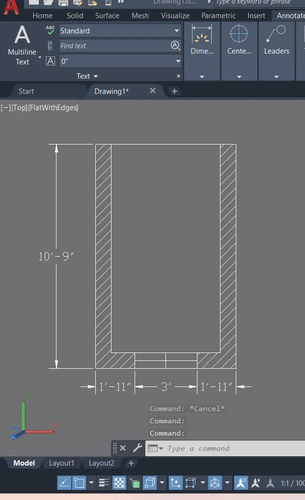
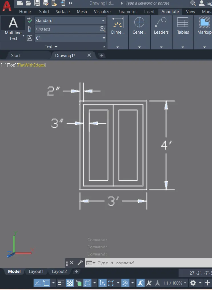
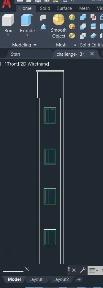
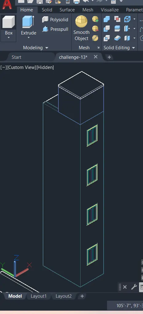
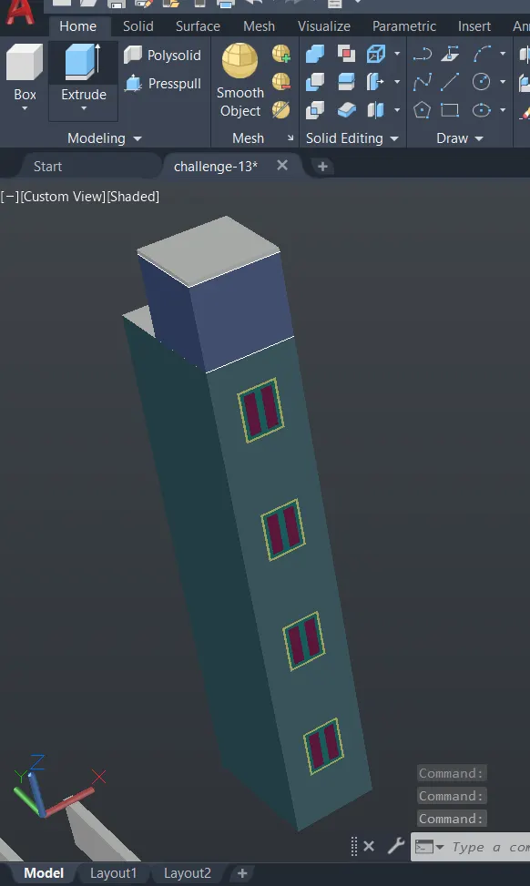
AIM : To Create the 3D View of the Building Façade as given in the plan and elevation.
Procedure for the building facade :
1.First open the auto cad software & create the drawing template in the folder.
2.prepare the drawing sheet as comfotable as like you by setting up & start up.
3.convert the drafting & annotation to the 3D basics or 3D modelling.
4.create the plan with multi line command with the given dimensions.
5.Give the height as per given dimensions in the shown figure of objects in z axis by extrude command.
6.shade the drawn objects by shade command.
7.draw the rectangle for creating window by rectangle command as per given dimensions and attach the solid to the wall of building where is it presented.
8.substract the window solid from the wall by using substract & union commands .use region command to fill the 2d object.
9.check the drawing by viewing the 360 degree view with the help of 3D orbit command & give the dimensions by DIM command.
10. give the obtained color to the building through the bylayer option or creating layers & draw the dimensions by using the dimension tool DIM .
11.save the completed drawing file ctrl+ s , take a snap of drawing upload it in the results.
Results:
2A.
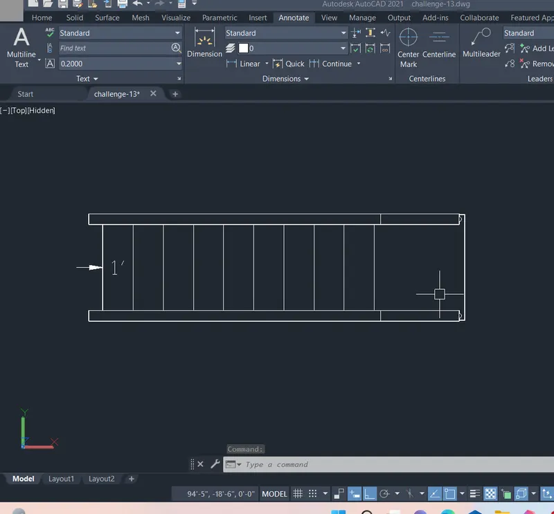
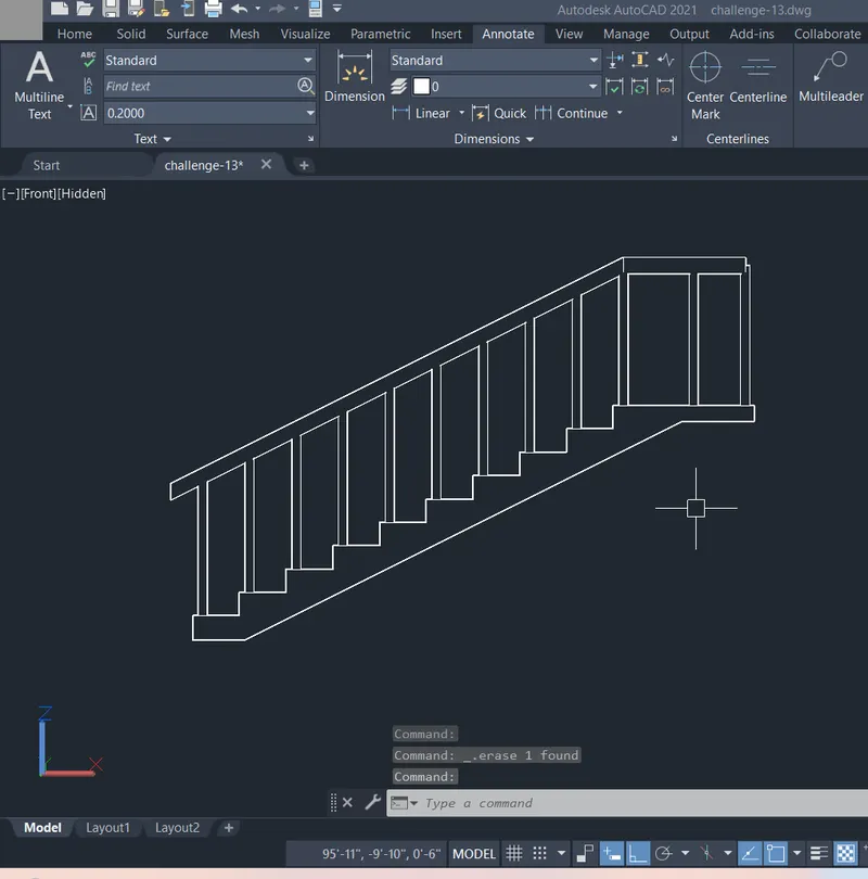
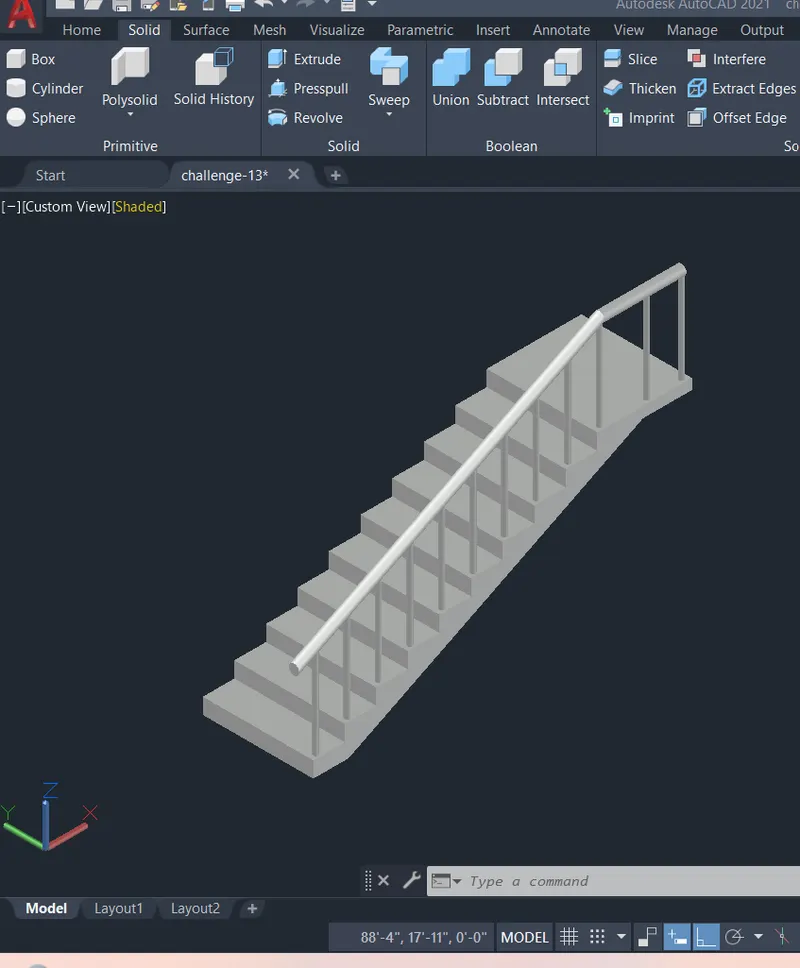
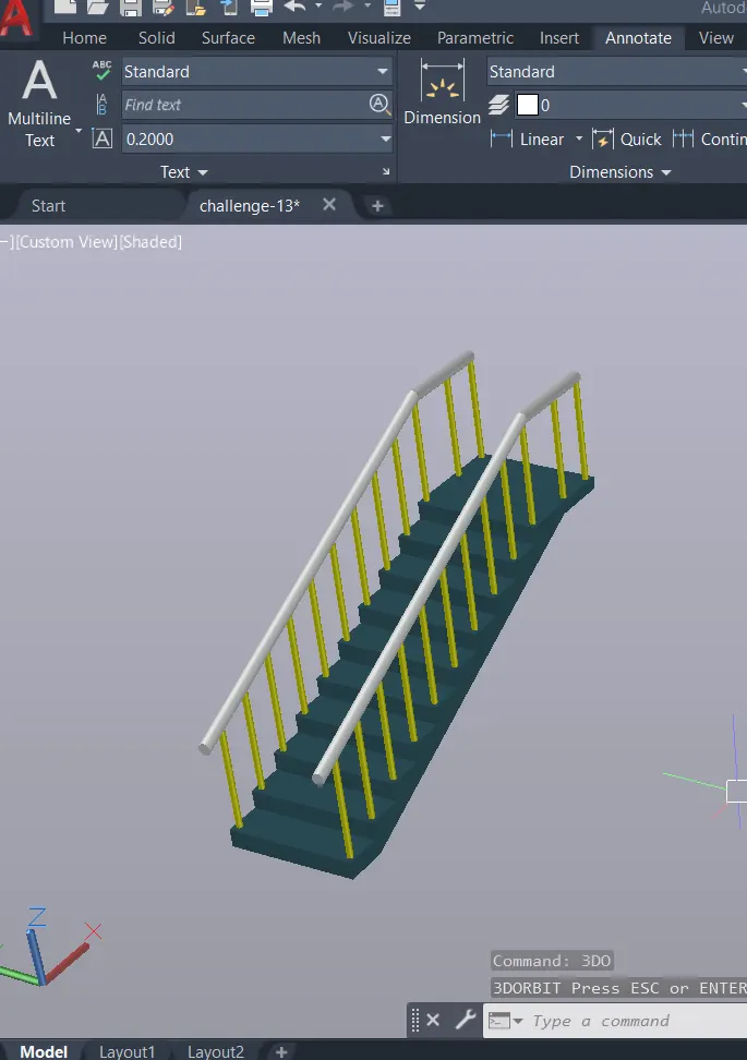
AIM : To Create the ismoteric 3d view of a stair with railing as shown in the plan and elevation.
Procedure for the stair case :
1.First open the auto cad software & create the drawing template in the folder.
2.prepare the drawing sheet as comfotable as like you by setting up & start up.
3.convert the drafting & annotation to the 3D basics or 3D modelling.
4.create the step with line commandas per the given dimensions ( thread = 1' ,rise = 6").and copy it up to the 10th step.and join all the steps as single object.
5.draw a circle and extrude it by the height of 3' and place a copies on the ach step.and connect the hand rail with the line command extrude the circle with in the path.
6.Give the width as 3.5' to the stair in y axis by extrude command next ,copy the hand rail on the other side.
7.shade the drawn objects by shade command.
8.use the substract & union commands where it is requried .use region command to fill the 2d object.
9.check the drawing by viewing the 360 degree view with the help of 3D orbit command & give the dimensions by DIM command.
10. give the obtained color to the building through the bylayer option or creating layers & draw the dimensions by using the dimension tool DIM .
11.save the completed drawing file ctrl+ s , take a snap of drawing upload it in the results.
Results:
4A.
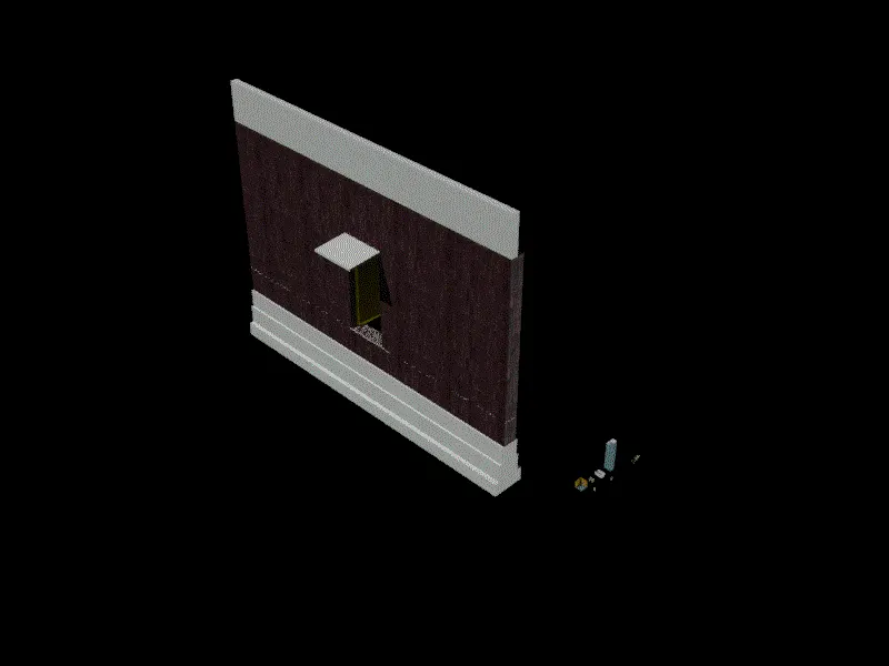
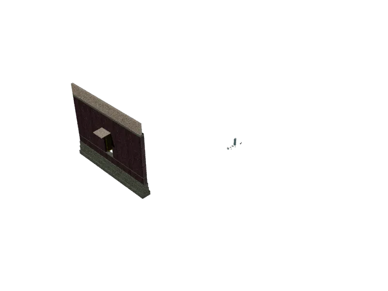
AIM : ToCreate the 3D view of a Wall with spread footing .
Procedure for the Footing :
1.First open the auto cad software & create the drawing template in the folder.
2.prepare the drawing sheet as comfotable as like you by setting up & start up.
3.convert the drafting & annotation to the 3D basics or 3D modelling.
4.create the section of the footing with line command in XY plane with the given dimensions.then rotate it to the z axis using 3Drotate command.
5.extrude the drawn figure with extrude command up to 7500 ,shade the drawn objects by shade command.
6.use the slice command to seperate the solid.and also use wedge command to create sloped solids like sunshade.
7.draw the rectangle for creating door by rectangle command as per given dimensions,then extrude it with height of 2100 and attach the solid to the wall of building where is it presented.
8.substract the door solid from the wall by using substract & union commands .use region command to fill the 2d object.
9.After the figure will complete go to the Materials Browser assigne the supposed colors or maaterials to the selcted solids or objects. then render the drawing by rendering option.then save the rastar or vector image to the folder.
10.check the drawing by viewing the 360 degree view with the help of 3D orbit command & give the dimensions by DIM command.
11. give the obtained color to the building through the bylayer option or creating layers & draw the dimensions by using the dimension tool DIM .
12.save the completed drawing file ctrl+ s , take a snap of drawing upload it in the results.
Results:
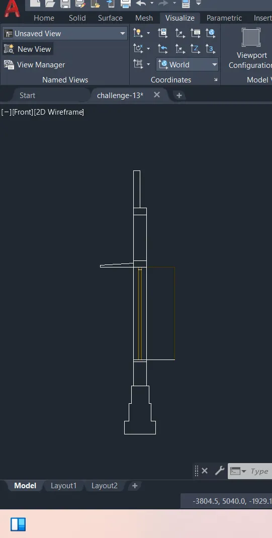
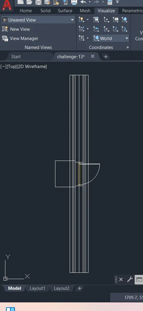
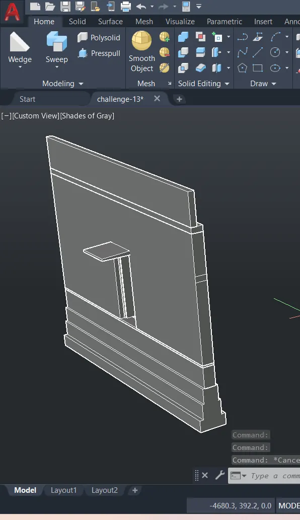

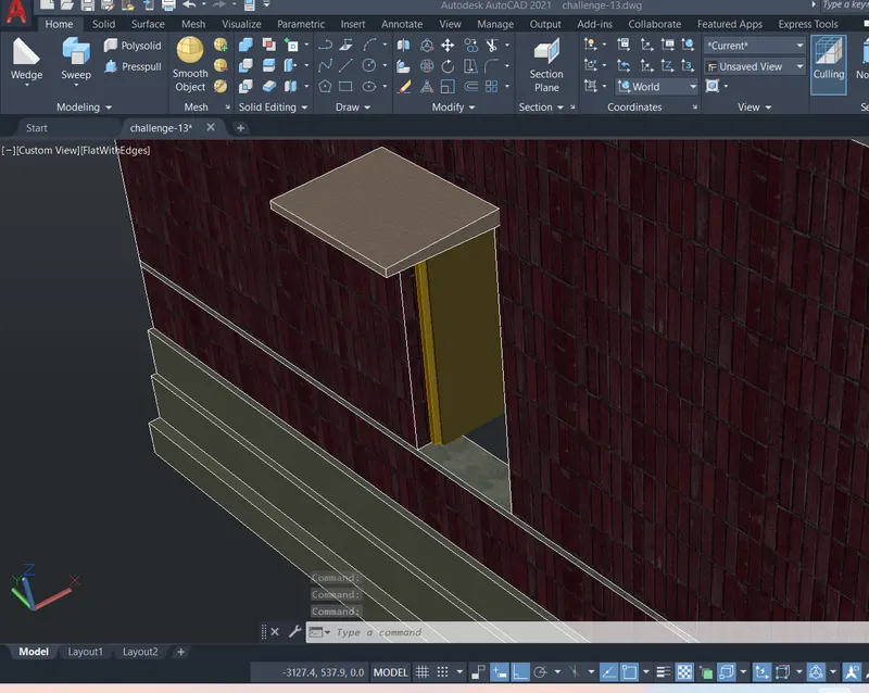
Rendered images :
FINAL RESULTS :
- The 3D Isometric view of various structural elements are drawn in AutoCAD.
- Drawn figures 1-4 are uploded in the above, like a picture.