Creating 3D Isometric view of various structural elements in AutoCAD
Aim 1:
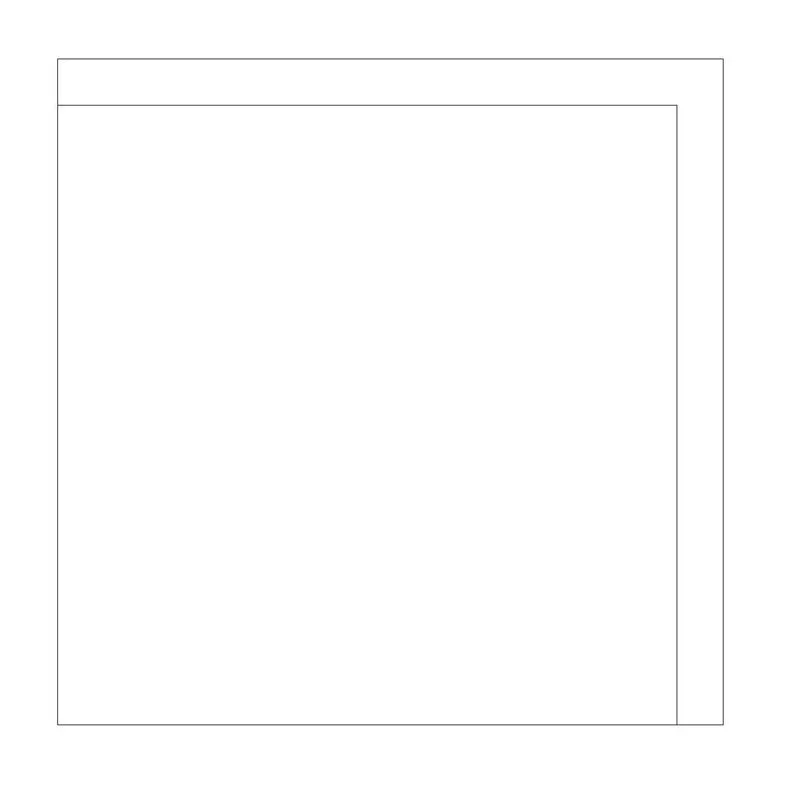
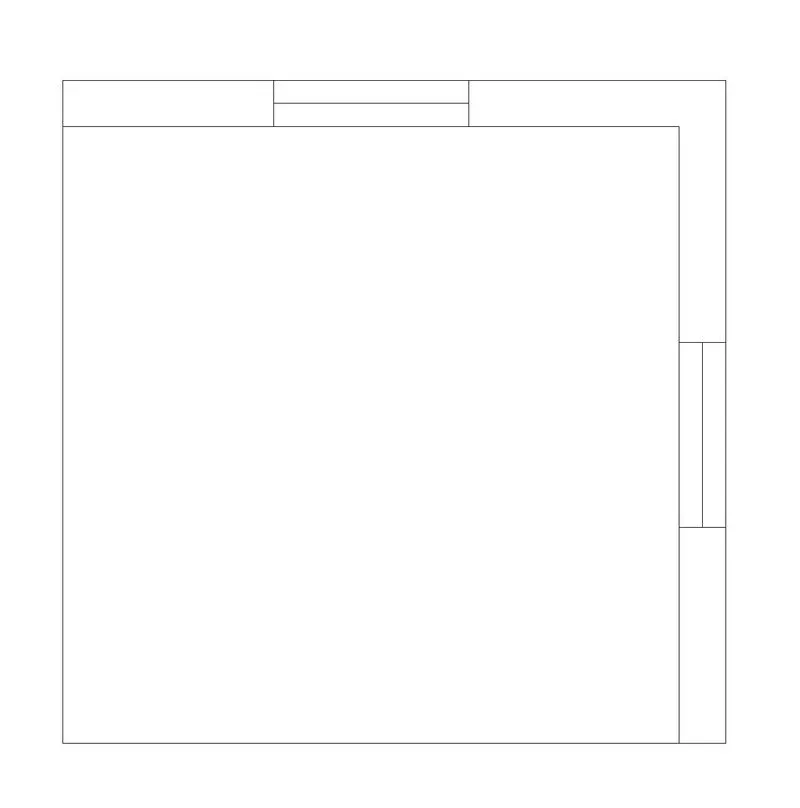
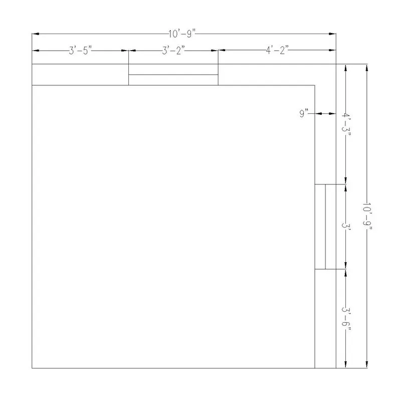
Create a 3D Isometric View of the building with plan and elevation given.
Procedure:
- Draw the plan outline using line tool.
- Draw the walls of 9" as given in the figure.
- Now Draw the windows at the given distances in the figure.
- Dimensioning the plan.
- now turn on the 3D modeling.
- Now with 3DFACE command make the wall face.
- with the help of EXTRUDE command extrude the wall as the given height 10'10".
- Open top view and draw the boundary rectangle.
- make the region of the rectangle.
- extrude this region about 4"
- copy this bottom 4" slab to top and increase its extrusion to 6".
- Enter UCS command and make the interior of the wall as working plane to make the window.
- Draw the window size and subtract it from the wall.
- Draw the 3" border of the window.
- Draw the 4" glass frame of the window.
- Now extrude the glass of window about 1" & group the 3 components of the window.
- Similarly draw the adjacent side window.
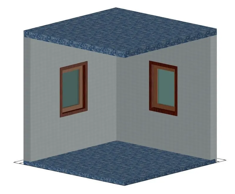
- Now Apply the materials on the solids.
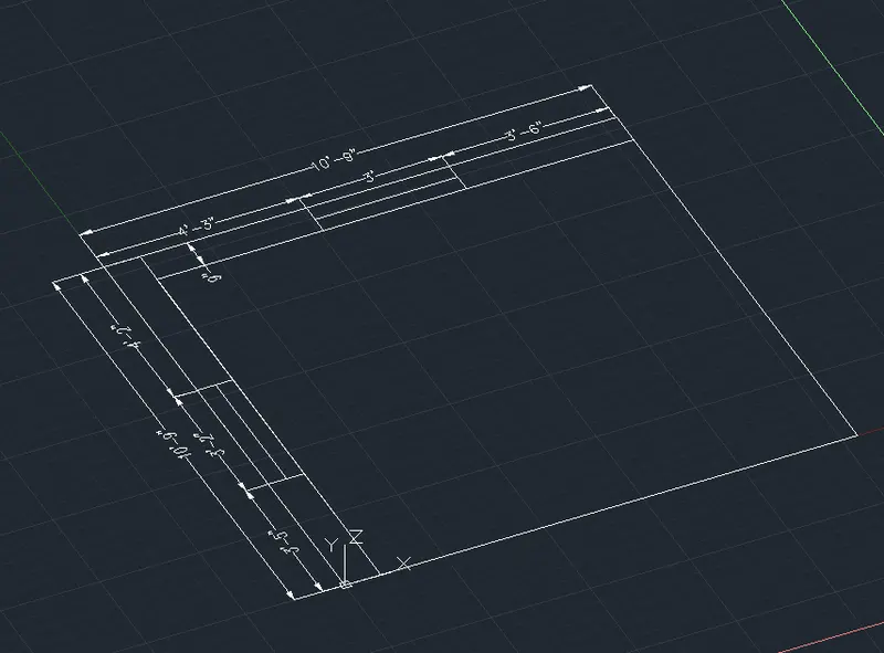
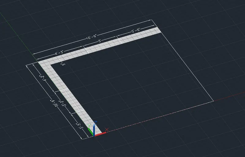
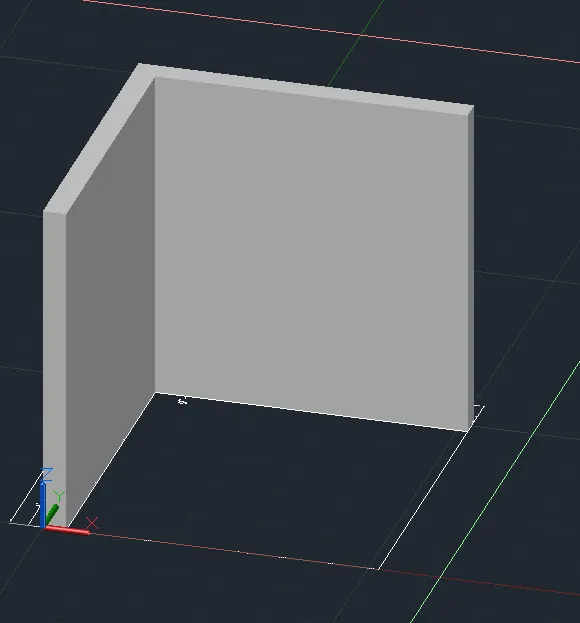
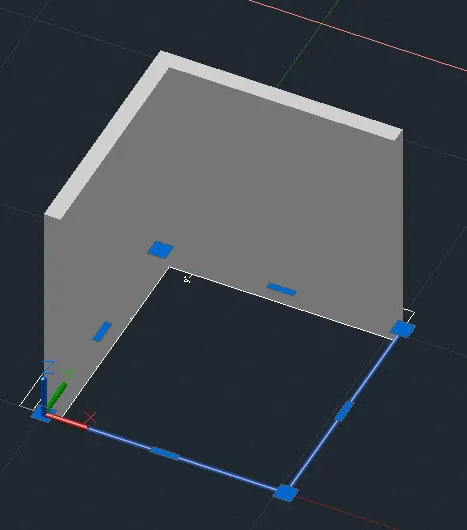
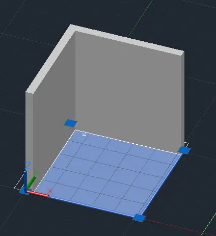
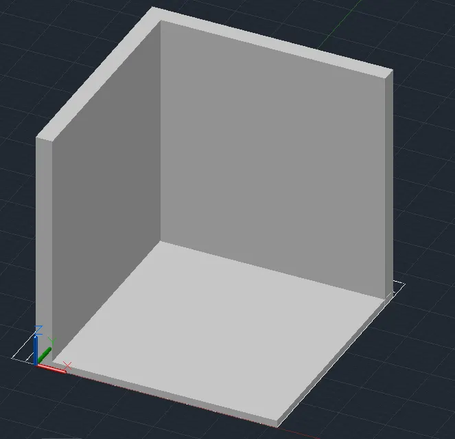
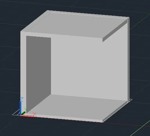
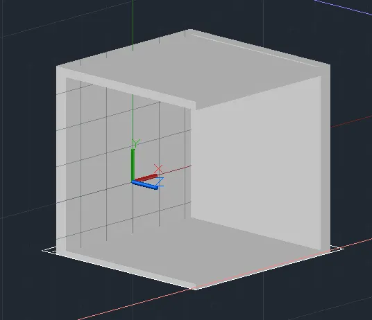
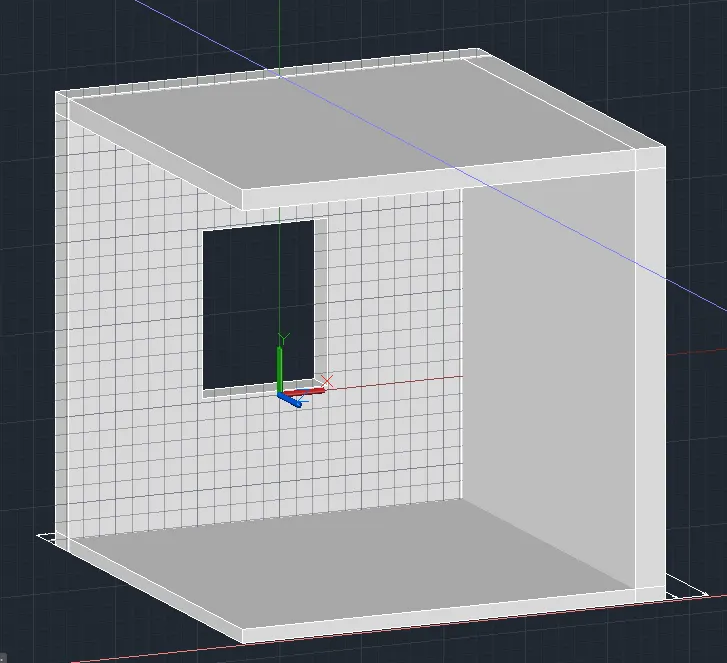
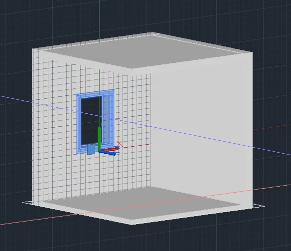
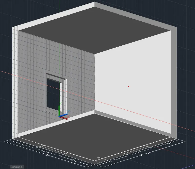
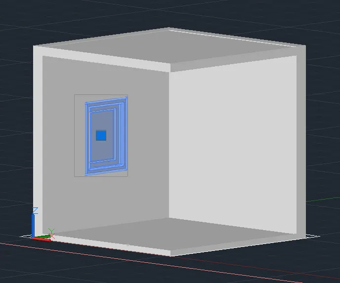
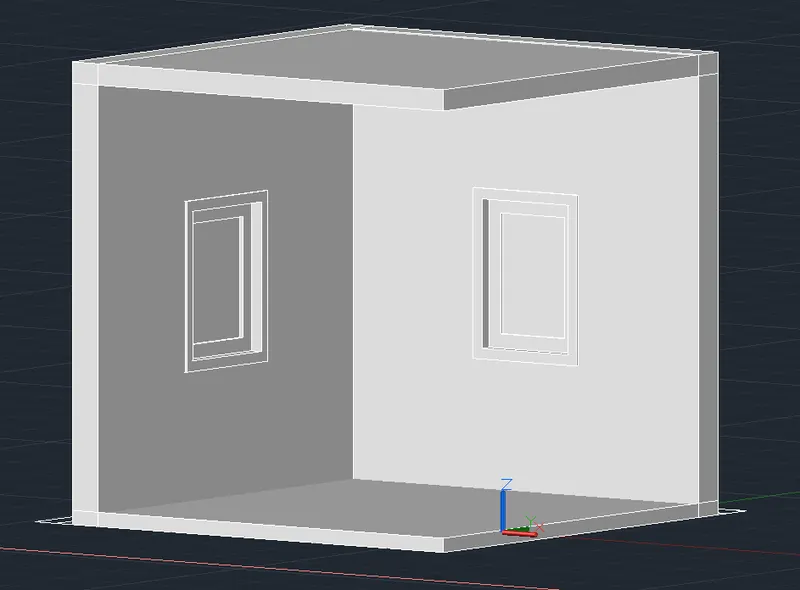
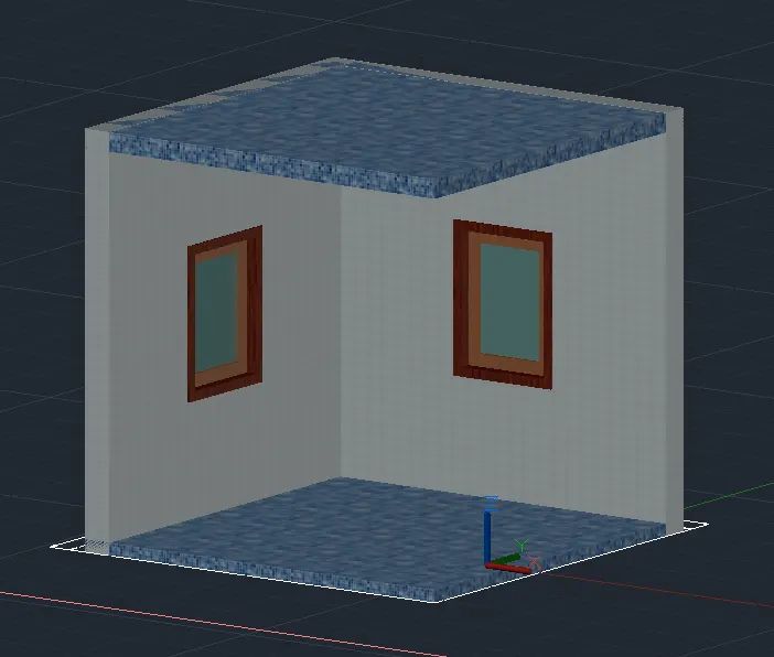
Final Result:
Aim 2:
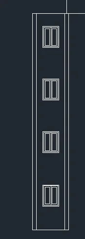
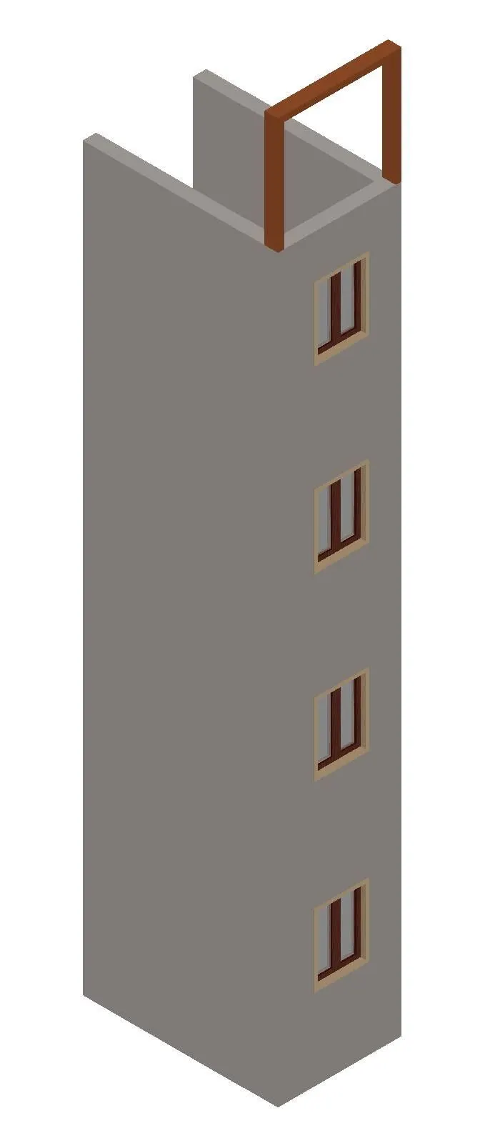
Create the 3D View of the Building Façade as given in the plan and elevation. Also, see the detail of the window.
Procedure:
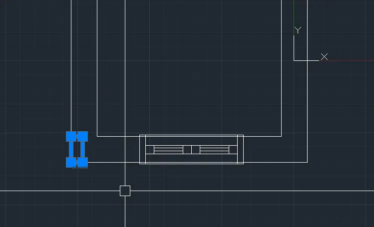
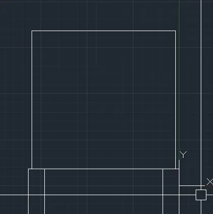
- Draw the top view and region the section and extrude it about 40'10".
- Now with UCS change the plane to make the openings of the window.
- region the window sections.
- Extrude the windows and cut the windows extrusion from the wall.
- Draw the Window frame of all windows.
- Now draw the opening of the windows glass frames.
- Enter the slice command to divide the opening into two parts.
- Now draw and extrude the glass of the window.
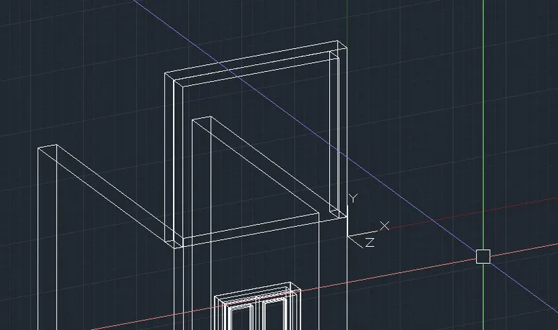
- Enter the UCS command and make the top as the working plane and draw profile of the top elevation.
- make the path of the profile and enter the sweep command to draw the elevation.
- Now apply all the materials to the components.
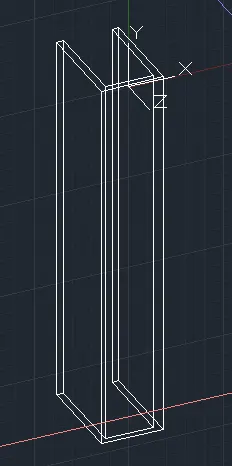
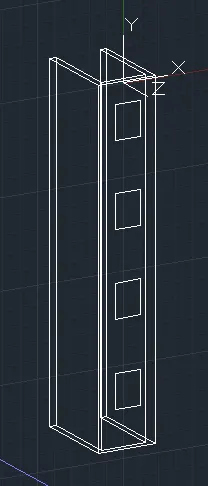
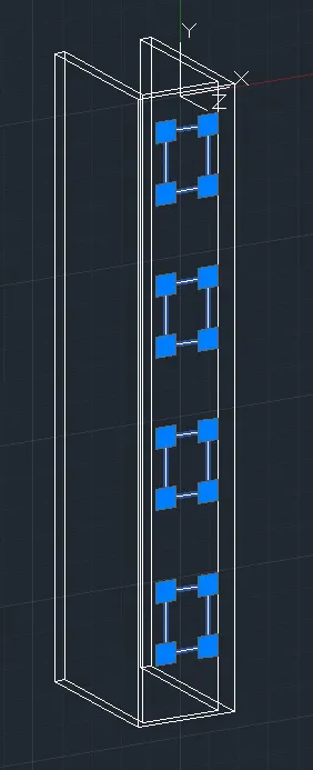
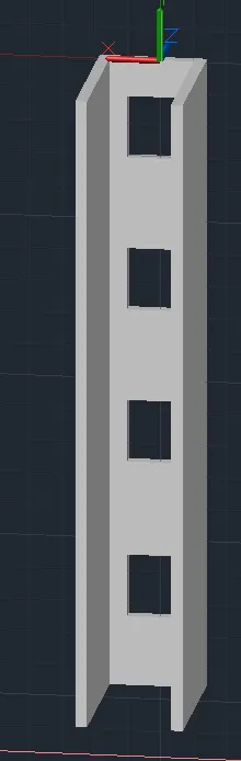
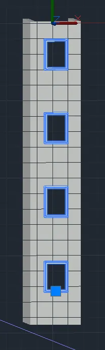
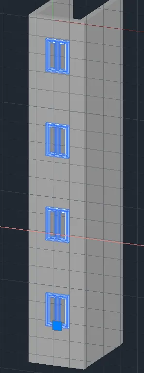
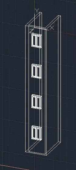
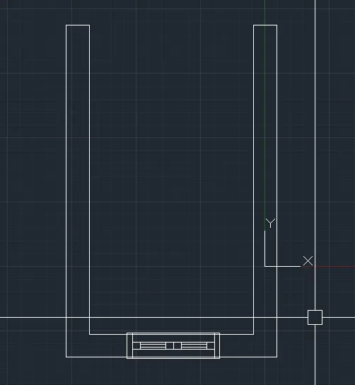
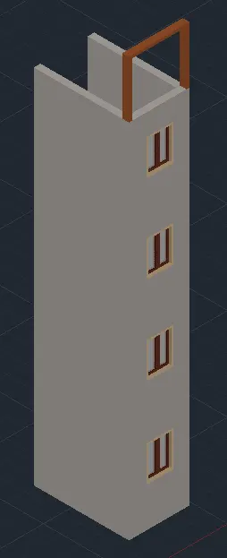
Final Result:
Aim 3:
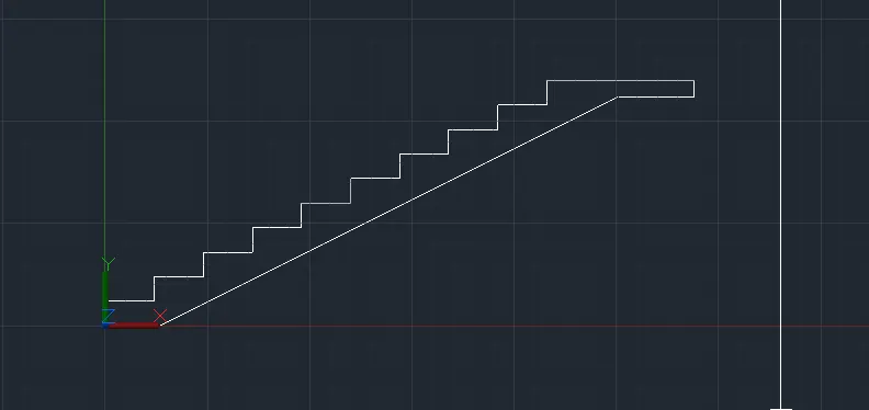
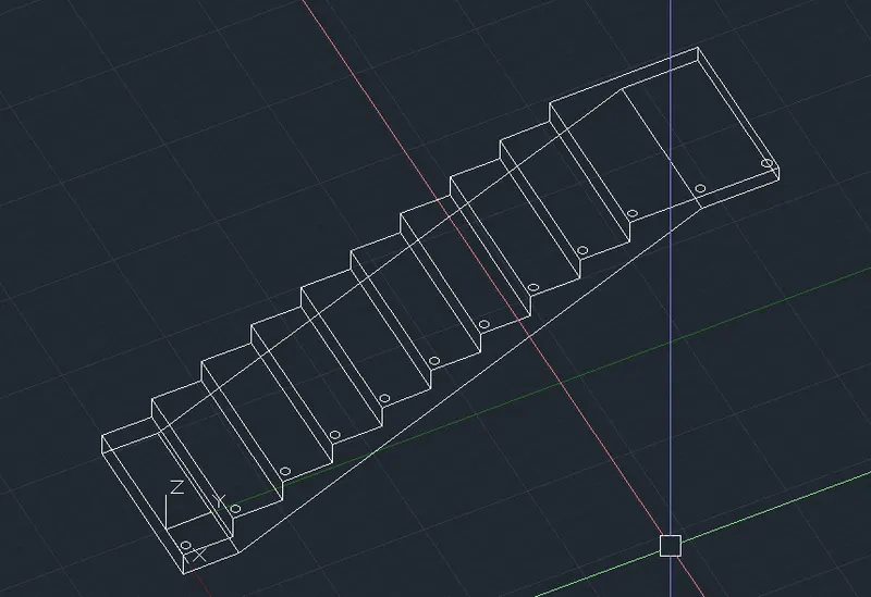
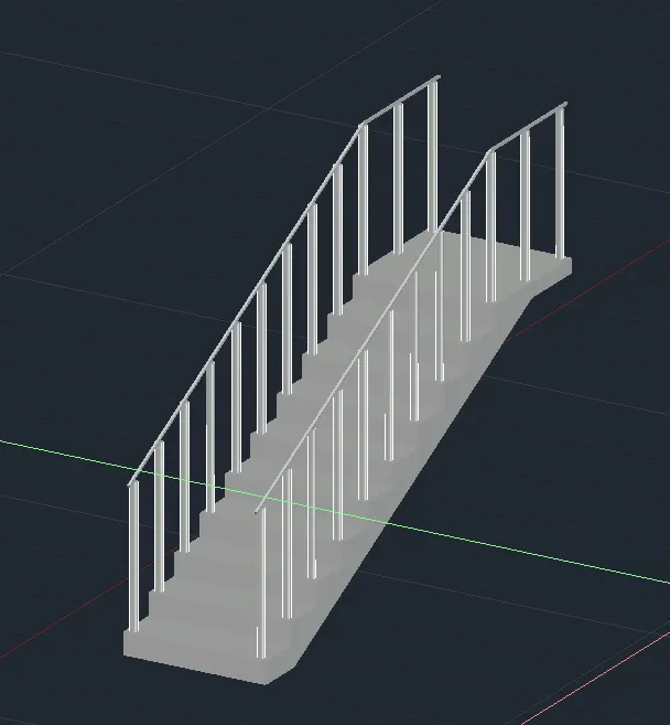
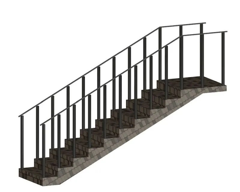
Create the ismoteric 3d view of a stair with railing as shown in the plan and elevation. Assume the size of the balustrades and the hand rails.
Procedure:
- Draw the elevation of the staircase.
- make the region of this elevation and extrude the region area.
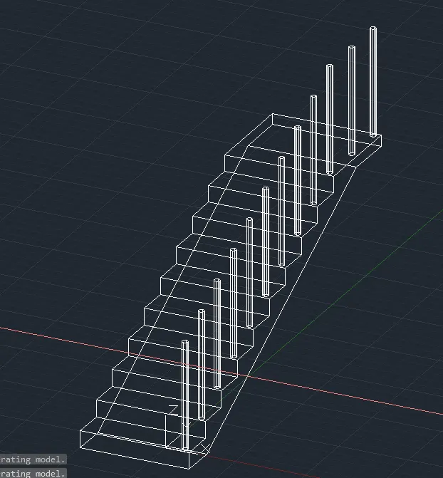
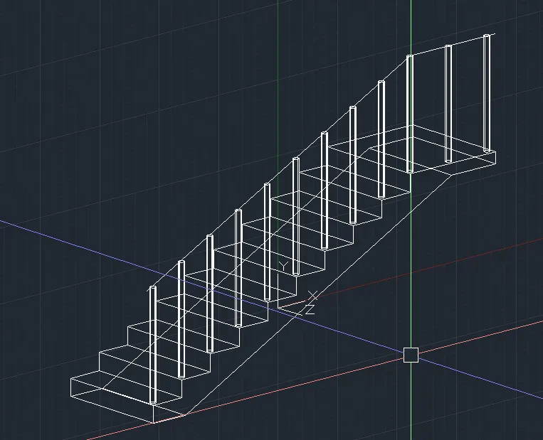
- Now change the work plane to the top of stairs and draw the railing vertical of the stairs.
- Extrude the circles to make 3D vertical support.
- Now change the UCS and draw the handle polyline.
- Create the profile and enter the sweep command and finish it & copy it to another side also.
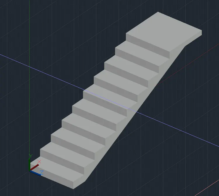
Final Result:
Aim 4:
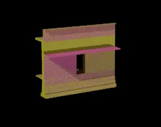
Create the 3D view of a Wall with spread footing . Create the Door opening only. Assume the size of the parpaet and the coping. See the plans and elevation for the details. Also, create a rendered view of the model with materials as of your choice.
Procedure:
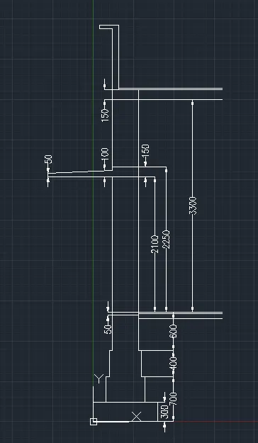
- Draw the Section of the given figure:
- make the region to make the surface extrusion.
- Make the door opening as per the top view given.
- Applying the material to the figure.
- Render the view and save the result.
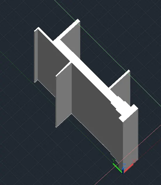
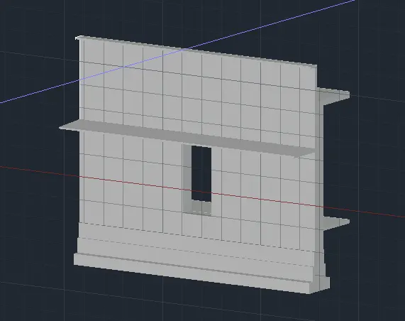
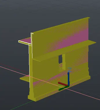
Final Result: