Creating 3D Isometric view of various structural elements in AutoCAD
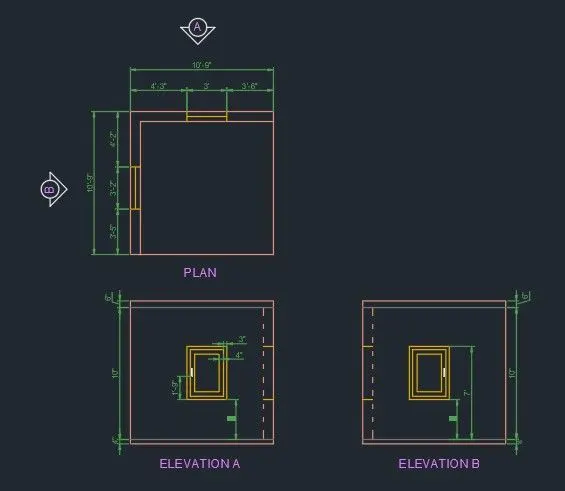
Aim-To create 3D isometric view of the building with plan and elevation given.
Introduction-All dimensions are in feet & inches. In this 3D elevation done by using autocad.
Procedure-
-Set unit in engineering with precison 0'0" and inches
-Set limit, i.e. lower is 0'0",0'0" and upper is 50'0",50'0"
-Set dimension style with given dimension
-Statr draw plan in 2D according to given dimension
-For elevation draw projection from plan and draw as per given figure.
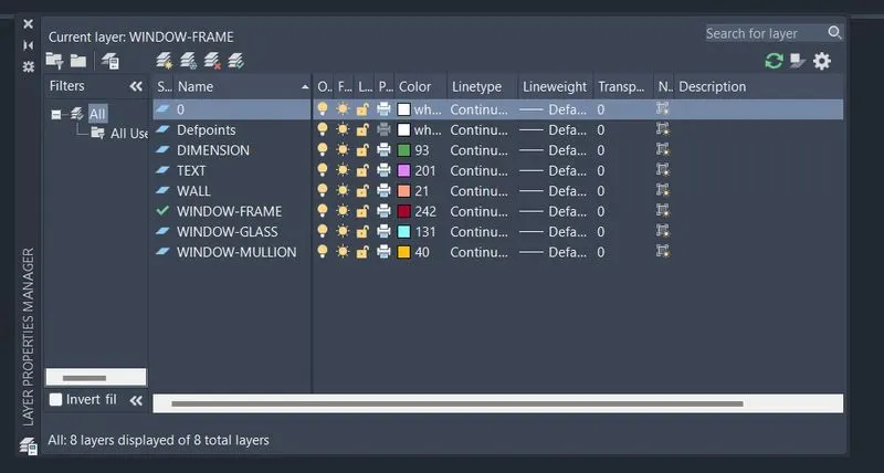
-LA enter and create each layer seprately and apply it
-After creating plan and elevation give proper dimension
-DT enter for text
-Now convert 2D to 3D modeling
-First create boundary for plan wall and extrude it upto 10'
-For wall below and above window make rectangle by setting UCS and extrude it.
-Union all walls
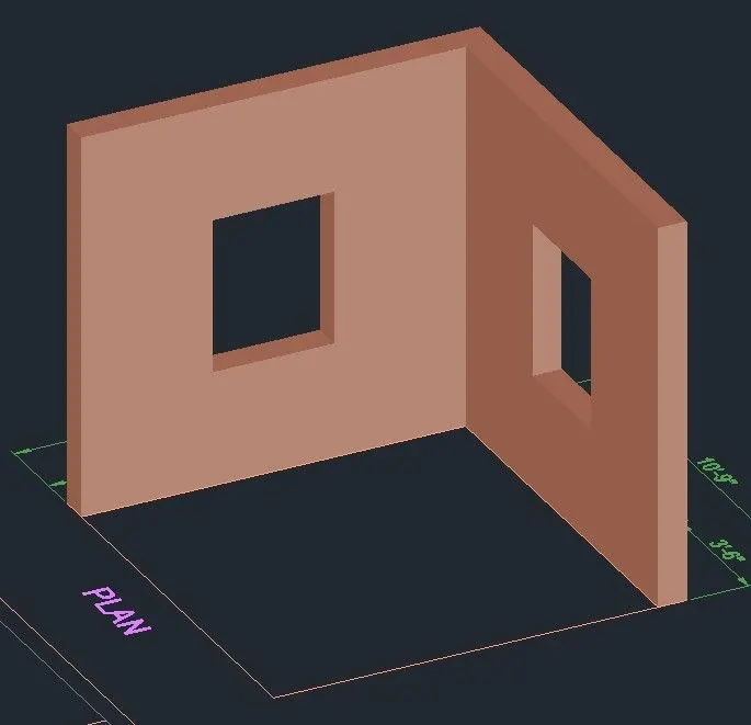
-To create window, take window from particular elevation then set UCS and rotate it
-Now make boundary first, subtract each layer properly
-According given layer extrude it 3" inside for window frame, 2" for window mullions and 1" for glass
-Move mullion 1" inside and 1.5" glass move inside also
-Now make whole window into group
-Put window at place and move it inside approx 3"
-Same for other window also
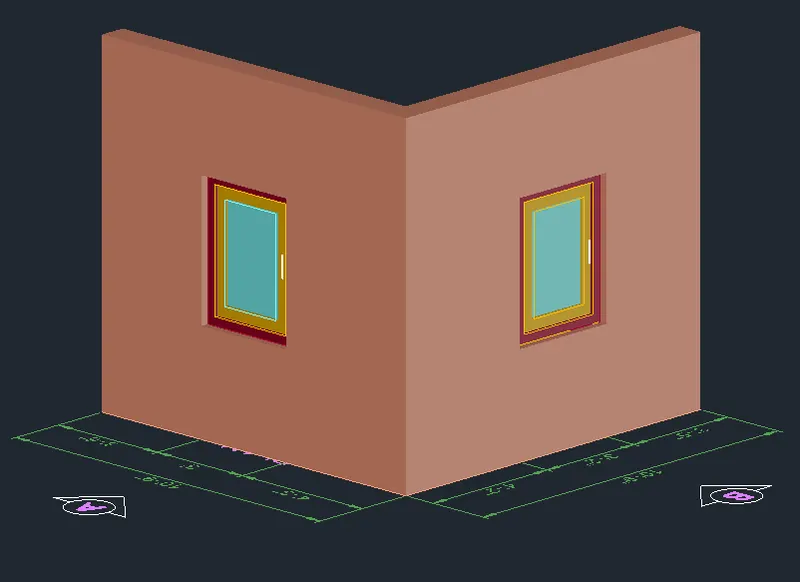
Result-
First plan drawn in 2D and then create in 3D
Aim-To create 3D view of building facade as given in plan and elevation
Introduction-All diemnsions are in feet & inches. In this window detail is given seprately for better understanding.
Procedure-
-Set unit in engineering with precison 0'0" and inches
-Set limit, i.e. lower is 0'0",0'0" and upper is 50'0",50'0"
-Set dimension style with given dimension
-Statr draw plan in 2D according to given dimension
-Seprate window is drawn to create 3D easily
-LA enter and create each layer seprately and apply it
-After creating plan give proper dimension
-DT enter for text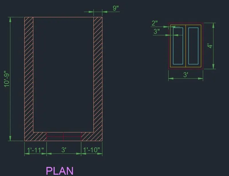
-Set sheet in 3D modelling
-Create boundary for walls and extrude it upto given dimension
-To create window, take window then set UCS and rotate it
-Now make boundary first, subtract each layer properly
-According given layer extrude it 3" inside for window frame, 2" for window mullions and 1" for glass
-Move mullion 1" inside and 1.5" glass move inside also
-Now make whole window into group
-Put window at place and move it inside approx 3"
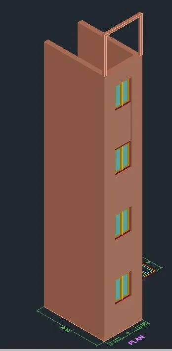
-After creating one window and placing it copy it in Zaxis at given dimension
-To provide walls between walls set UCS and create rectangle and extrude it
-Now to draw tower Set UCS and 3P for polyline accoring to given dimension
-In front elvation provide dimesion after setting UCS
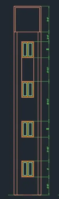
Result-
This is the final sketch in 3D front elvation
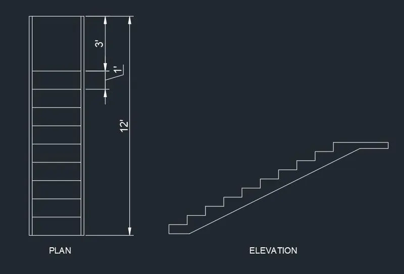
Aim-To create isometric 3D view of stair with railling as shown in plan and elevation by using autocad
Introduction-All dimensions are in feet & inches. Assuming missing dimensions. first draw in 2D and then in 3D
Procedure-
-Set unit in engineering with precison 0'0" and inches
-Set limit, i.e. lower is 0'0",0'0" and upper is 50'0",50'0"
-Set dimension style with given dimension
-First draw stair in 2D plan and elevation both as per given dimension
-In plan dimension given by DIMLIN command
-
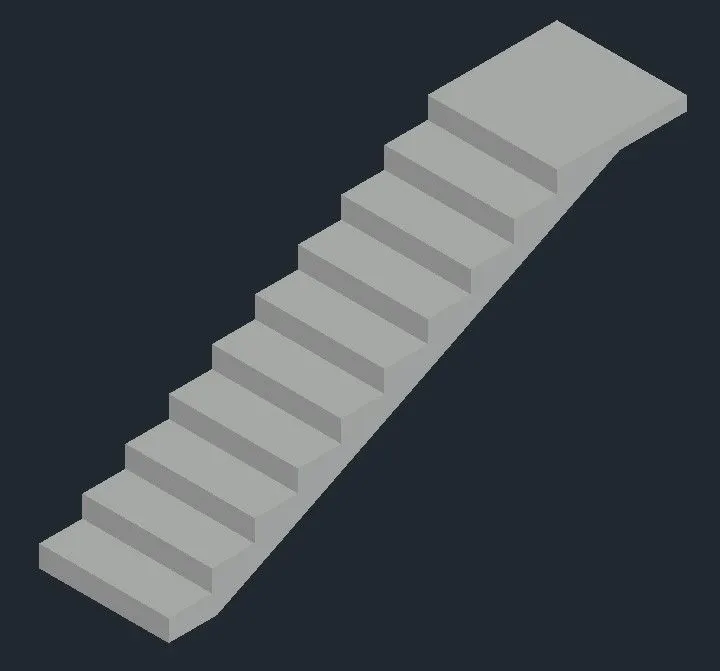
-Now covert 2D to 3D modelling take elevation set UCS and rotate elevation
-Create boundary for elevation of stair and extrude it 3' as a width
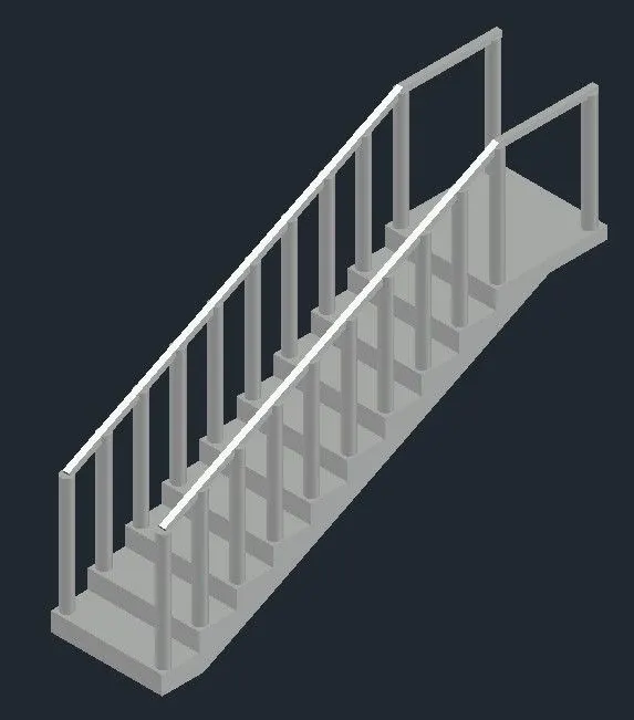
-To create railing set UCS on 1st step of staiecase take 2" of circle then extrude it upto 3'2"
-Copy this circle on every stairs nd on landing also
-Take 3D polyline to draw railing and sweep it with rectangle
-Copy this railing to other side also.
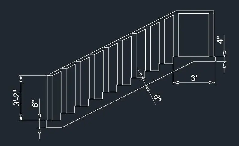
-Now go to front view and hidden profile
-Set UCS and dimension to it
Result-
This is final sketch of3D staircase by using autocad.
Aim-To create 3D view of wall with spread footing and rendered view of model with material.
Introduction-All dimension are in mm. Choice of material is asuume and height of camera also
Procedure-
-Set unit in decimal with precison 0.
-Set limit, i.e. lower is 0,0 and upper is 20000,20000
-Set dimension style with given dimension
-Start drawing in 2D first as per given dimension
-First draw plan and then section of wall with given dimension respectivly
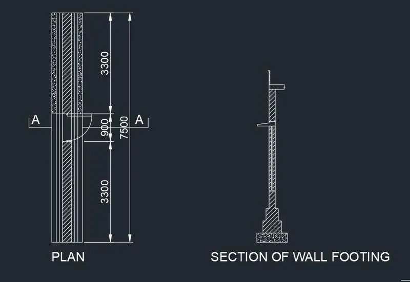
-Now make sheet in 3D modelling
-Take section of wall and rotate it
-Make it boundary and extrude it
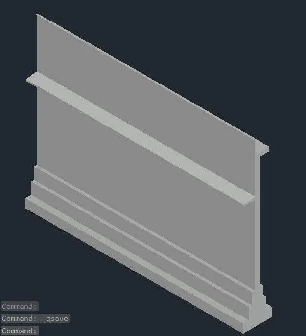
-As per the plan there is door of 900 so put the UCS on face where we want to create a door
-Now draw door as per the given dimension and at given place
-Make it region then extrude it and then subtract it
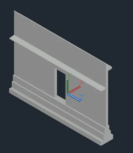
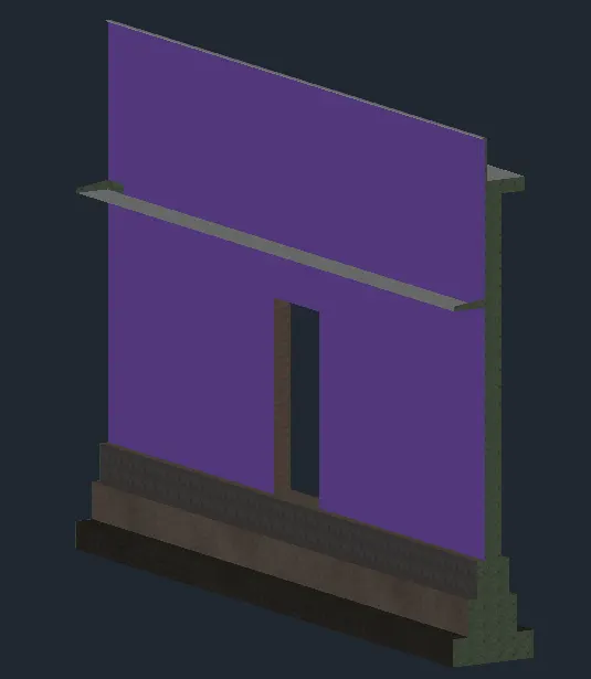
-Type MAT for material and give it to this
-Create rectangle in top view as a ground floor and extrude it -50mm
-Create circle on the corner of this ground floor and extrude it upto 3m and out camera on it
-3Dorbit to set proper view
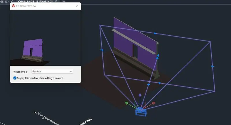
-Now for rendering RR in command
-Environment phase on
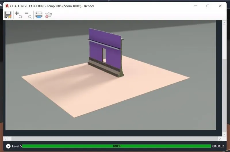
-We can save this image as png. jpg etc.
Result-
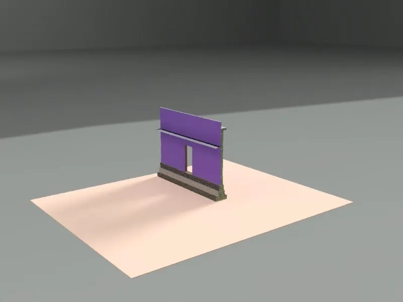
In this jpeg image provided for reference