Creating 3D Isometric view of various structural elements in AutoCAD
AIM : Create a 3D Isometric View of the building with plan and elevation given.
INTRODUCTION:
An isometric drawing is a 3D representation of an object, room, building or design on a 2D surface. we have used various command in this drawing such as extrude, subtract, boundary, union et
PROCEDURE :
step-1 :
- Open autocad select imperial feet inches
- set unit to engineering inches
- select workspace > 3d modelling
- select 2dwireframe > go to 2d mode to draw plan
- go to layer properties make different layer for drawing
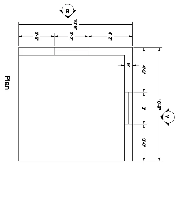
- type line > make a rectangle of dimensions 10'9" x 10'9"
- type offset > offfset distance 9" > select two side of rectangle > give offset inside the recangle
- type fillet > fillet the corner
- next step make window
- give offset of 3'5" to vertical line which is at left side
- then offset of 3'2"
- trim the unwanted lines
- type line command make middle line for window
- give offset of 3'6" to horizontal bottom line
- then offset of 3'.
- trim the unwanted lines
- type line command make middle line for window
- type dimlin provide dimensions
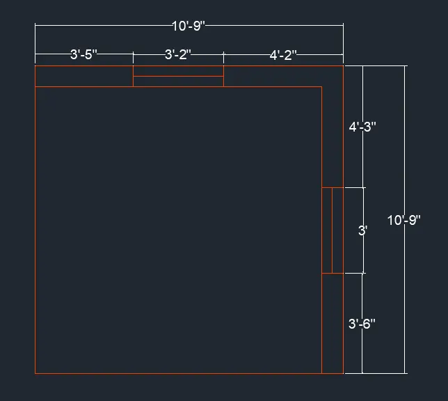
- type boundary .> select region > pick point > select object to give boundary
- type extrude command > extrude the boundary region > upto 10'6" height in positive
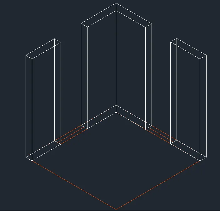
- type rec . make rectangle at top of between two extrusion
- make rectangle joining two corner point
- do this for two side of wall
- type boundary .> select region > pick point > select object to give boundary
- type extrude command > extrude the boundary region > upto 3'6" height in negative
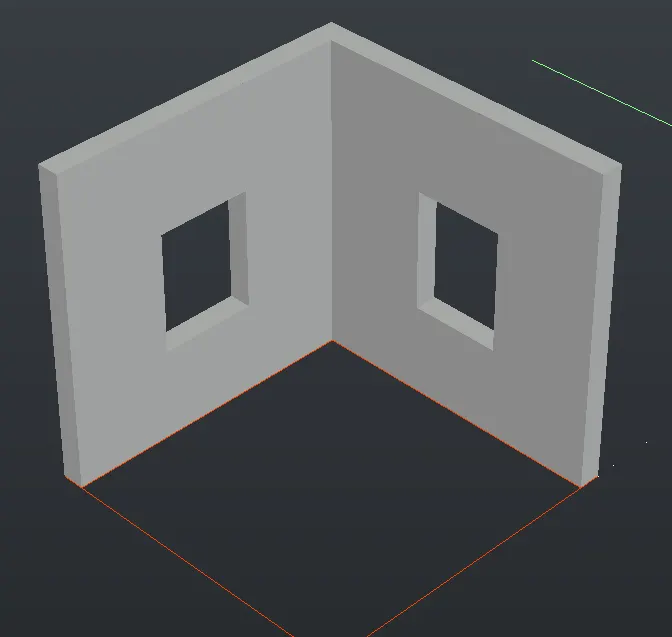
- give the floor
- type boundary .> select region > pick point > select object to give boundary
- type extrude command > extrude the boundary region > upto 4" height in negative
- type union > join the all extrusion > make single entity
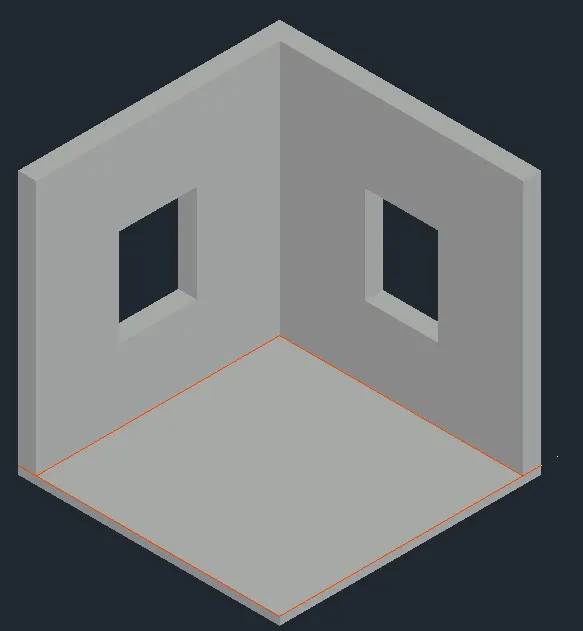
step-2 : making windows
- go to 2d mode wireframe
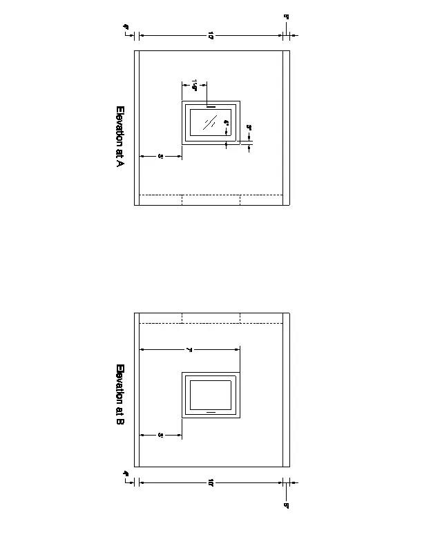
- set the ucs in such a way that window must be align to elevation
- type rec > give dimensions >3' x 4'
- type offset > offset distance 3" > give offset inside the rectangle
- type offset > offset distance 4" > give offset inside the rectangle
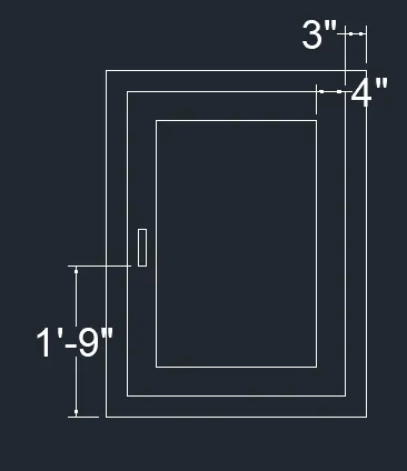
- select layer of window panel
- type boundary .> select region > pick point > select object to give boundary
- type subtract > subtract the inner rectangle from outer rectangle
- repeat the procedure for inner rectangle
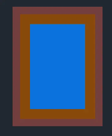
- set the ucs in such a way that window must be align to elevation
- type rec > give dimensions >3'2" x 4'
- type offset > offset distance 3" > give offset inside the rectangle
- type offset > offset distance 4" > give offset inside the rectangle
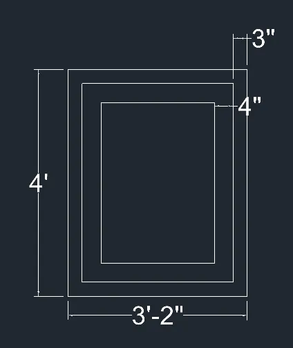
- select layer of window panel
- type boundary .> select region > pick point > select object to give boundary
- type subtract > subtract the inner rectangle from outer rectangle
- repeat the procedure for inner rectangle
- type move command paste this window in elevation
- keep ortho off
- keep in 2d wireframe workspace
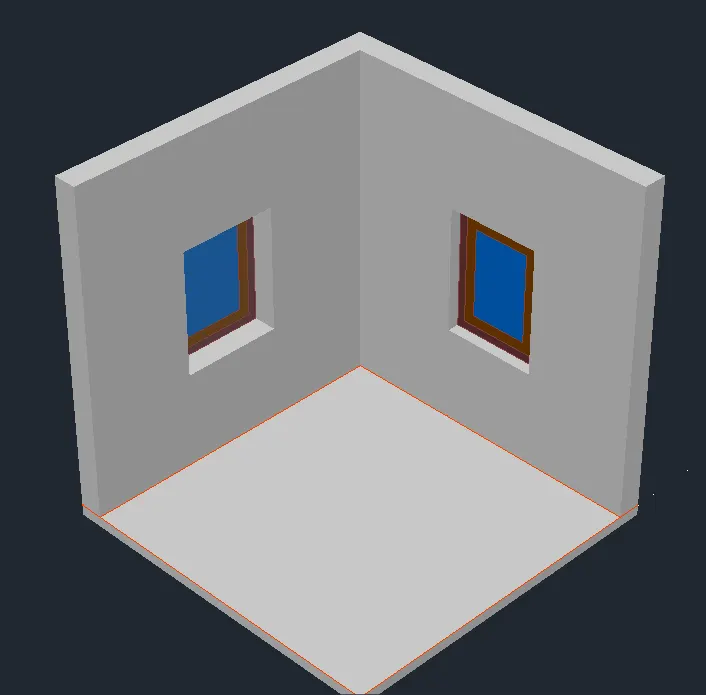
RESULT :
We have Created a 3D Isometric View of the building with plan and elevation given
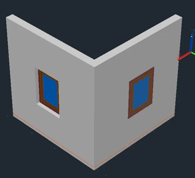
2.
AIM:
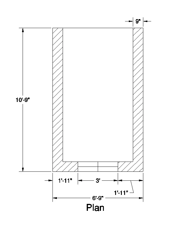
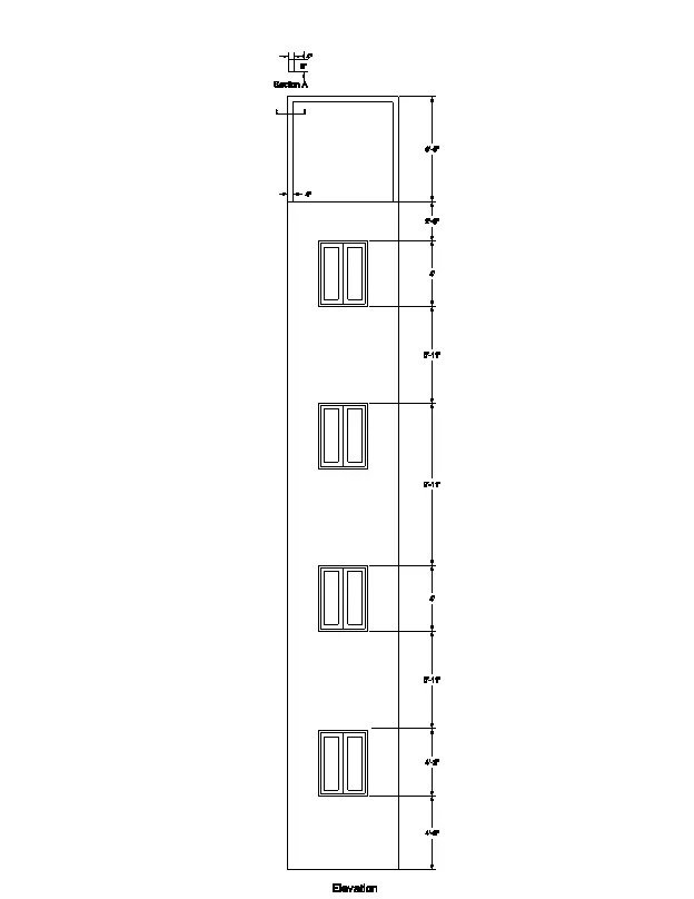
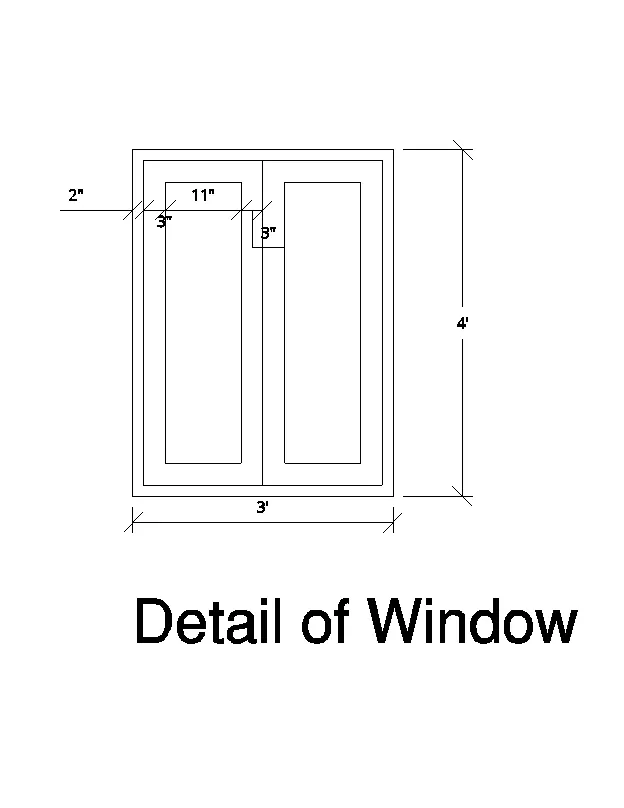
Create the 3D View of the Building Façade as given in the plan and elevation. Also, see the detail of
the window.
INTRODUCTION :
An isometric drawing is a 3D representation of an object, room, building or design on a 2D surface. we have used various command in this drawing such as extrude, subtract, boundary, union etc.
PROCEDURE :
step-1
- Open autocad select imperial feet inches
- set unit to engineering inches
- select workspace > 3d modelling
- select 2dwireframe > go to 2d mode to draw plan
- go to layer properties make different layer for drawing
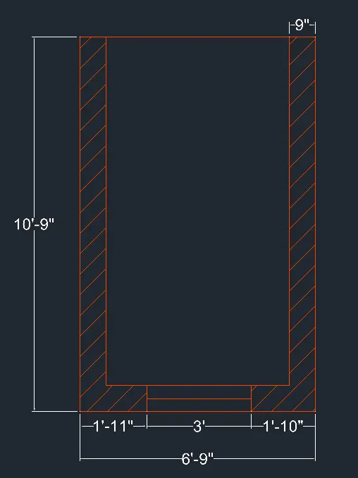
- type line > make a rectangle of dimensions 6'9" x 10'9"
- type offset > offset distance 9" >
- offset the 3 side of rectangle
- for window give vertical offset of 1'11", then 3' offset
- trim the unwanted line
- type hatch > provide hatch
- type dimlin > provide dimension
step-2 :
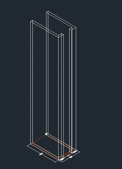
- go to parallel 3d view
- type boundry > select region > pick point
- extrude > select object to extrude > give height of 40'10"
step-3 :
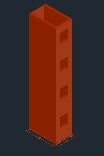
type boundry > select region > pick point
- extrude > select object to extrude > give height of 4'6"
- type boundry > select region > pick point
- extrude > select object to extrude > give height of 4'2"
- type boundry > select region > pick point
- extrude > select object to extrude > give height of 5'11'
- type boundry > select region > pick point
- extrude > select object to extrude > give height of 4'
- type boundry > select region > pick point
- extrude > select object to extrude > give height of 5'11"
- type boundry > select region > pick point
- extrude > select object to extrude > give height of 4'
- type boundry > select region > pick point
- extrude > select object to extrude > give height of 5'11"
- type boundry > select region > pick point
- extrude > select object to extrude > give height of 4'
- type boundry > select region > pick point
- extrude > select object to extrude > give height of 2'5"
- delete the windows position extrusion
step-4 :
- make window
- type rec > select dimensions > 3'x4'
- type offset > offset dist 3" > offset the rec inside
- type line > draw a line middle point of rec
- offset the rec 3" inside again
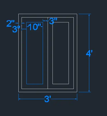
- select layer of window panel
- type boundary > select region > pick point > select object to give boundary
- type subtract > subtract the inner rectangle from outer rectangle
- repeat the procedure for inner rectangle
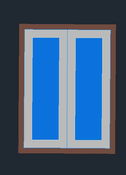
- set ucs properly
- copy the window and set on the position of window provide in elevation
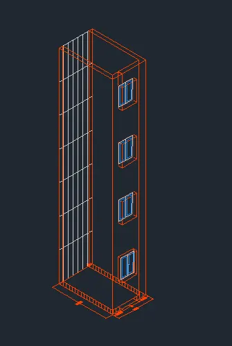
step-5 :
- make roof of building
- type rec > make rec on top
- type region > select rec
- type extrude > height -4"
- set the ucs properly draw the cutting section
- type line > make rec of 6'9" x 6'5"
- type region > select rec
- type extrude > height -4"
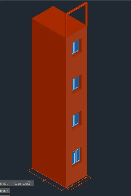
RESULT :
we have Created the 3D View of the Building Façade as given in the plan and elevation.
3.
AIM :
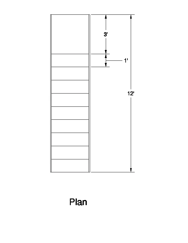
Create the ismoteric 3d view of a stair with railing as shown in the plan and elevation. Assume the size of the balustrades and the hand rails.
INTRODUCTION :
An isometric drawing is a 3D representation of an object, room, building or design on a 2D surface. we have used various command in this drawing such as extrude, subtract, boundary, union etc. Assume the size of the parpaet and the coping. See the plans and elevation for the details. Also, create a rendered view of the model with materials as of your choice. We have Assumed the size of the balustrades and the hand rails.
PROCEDURE :
step-1 :
- Open autocad select imperial feet inches
- set unit to engineering inches
- select workspace > 3d modelling
- select 2dwireframe > go to 2d mode to draw plan
- go to layer properties make different layer for drawing
- type plan and press enter
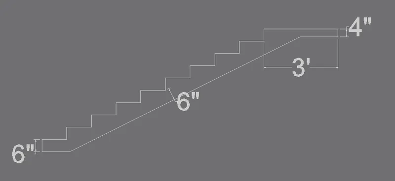
- type line command and draw a line vertical 6" dist and then horizontal line 1'
- type copy > copy the item 10 times
- at end extend the line 2' so we will get 3' landing
- give offset of 6" to inclination
step-2 :
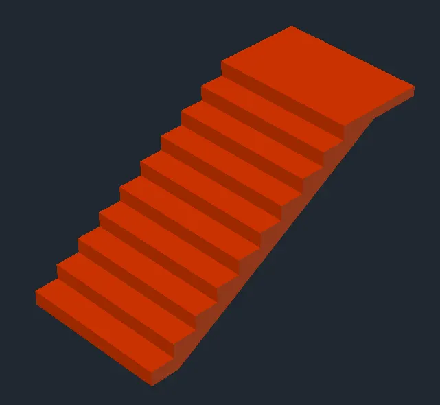
- type boundary > select region > select pick point and give region to object
- go to 3d view
- type 3drotate > select object > select axis > give rotate angle
- type extrude > select object and give 5' width to staircase
step-3:
- type ucs > set the ucs
- go to layer select different colour layer
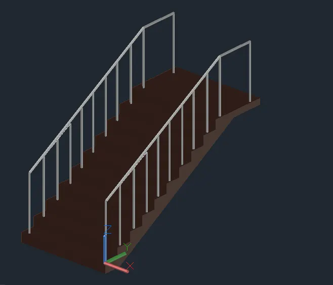
- type c for circle make circle on stair
- extrude the circle upto height 3'
- copy the baluster and paste on every stairs
- type 3dpolyline .> connect the top of point and provide line
- draw a circle
- type sweep command select the circle and press enter > select the line and press enter
- copy this railing to other side of stairs
RESULT :
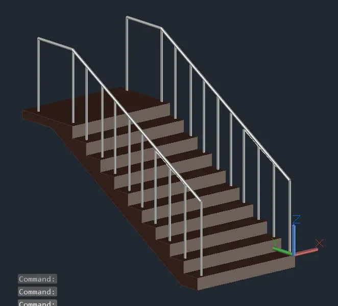
We have Created the ismoteric 3d view of a stair with railing as shown in the plan and elevation.
4.
AIM :
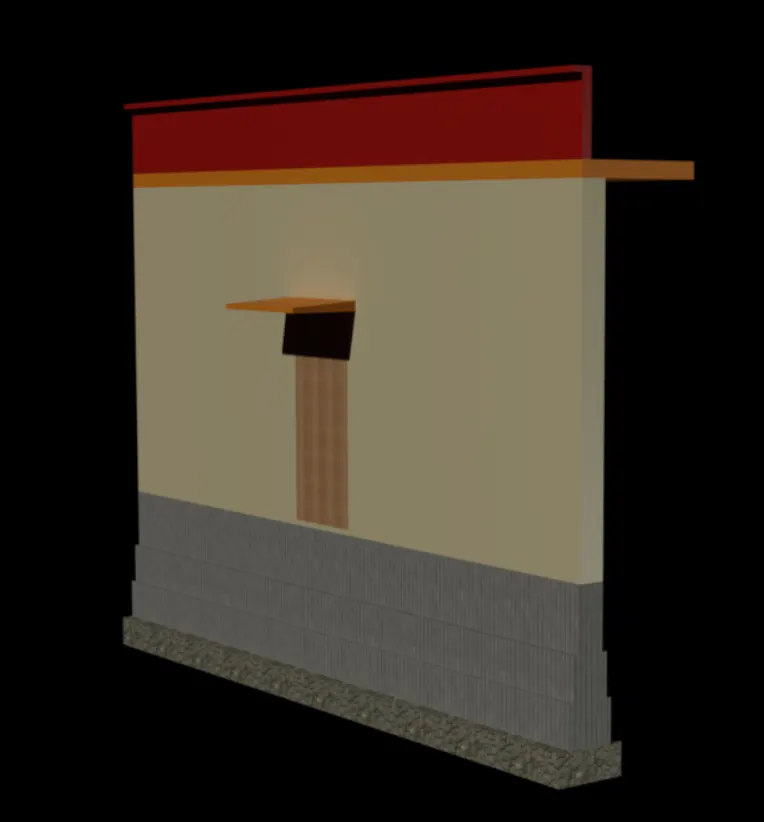
Create the 3D view of a Wall with spread footing . Also, create a rendered view of the model with materials as of your choice.
INTRODUCTION :
An isometric drawing is a 3D representation of an object, room, building or design on a 2D surface. we have used various command in this drawing such as extrude, subtract, boundary, union etc.We have Assumed the size of the parpaet and the coping. we have taken refernce of the plans and elevation for the details. Also, we have created a rendered view of the model with materials as of your choice.
PROCEDURE :
step-1 :
- Open autocad select metric
- set unit > decimal > milimeter
- select workspace > 3d modelling
- select 2dwireframe > go to 2d mode to draw plan
- go to layer properties make different layer for drawing
- type plan and press enter
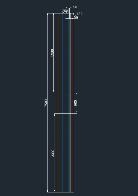
- type rec > give dimensions > 250 x 7500
- type offset and give continuous offset of 50,50,120
- type trim> trim unwanted line
- type explode > explode the inner rectangle
- type offset and offset the bottom most horizontal line > offset distance 3300
- type offset again offset the line distance of 900
step-2 :
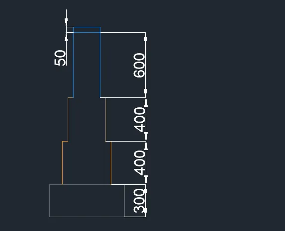
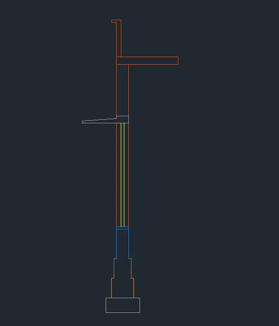
- take reference of above plan
- make line using projection of plan
- taking the refrence from drawing make following section
- type boundary > select region > pick point > give boundary to all diagram
step-3 :
- type 3d rotate >select object > select base point > give axis
- rotate the above digram
- set ucs
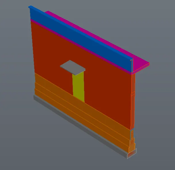
- type extrude > select object > extrude distance -7500
- select the side to provide door
- set ucs
- make rectangle
- type subtract > select bigger rect > then door rectanle
- adjust chajjas
step-4 :
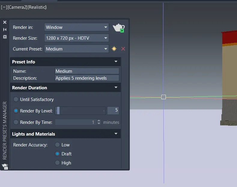
- select material browser
- select material > select object > select assign
step-5 :
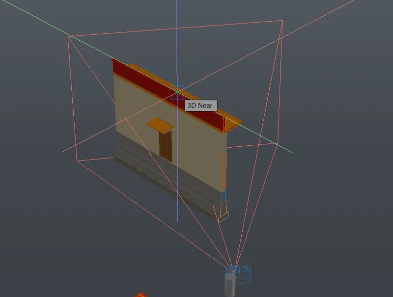
- select create camera
- set camera position
- set camera .> height > view
- save view
step-6 :
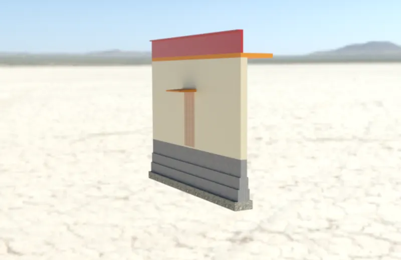
- select render
- set background env .> image quality > lights
- type rr for render
RESULT :
we have Created the 3D view of a Wall with spread footing . Also, we have created a rendered view of the model with materials as of your choice.