Creating 3D Isometric view of various structural elements in AutoCAD
AIM TO DRW THE ISOMETRIC VIEW OF THE BUILDING
PROCEDURE
1 open autocad
2 select a new heet from the home rebbon
3 now select the units
4 now draw a rec of 10.9,10.9
5 give it a offset of 4 from the left line and give it a offst of 6 from the right
6 now leave heigh of 3 and draw a rec at the center of the big rec now give it a offset of .4,.3
7 now use the line type command to change the line to dash line
8 decrease the spacing between the dashes
9 now give a offset of 3 from the bottom line and div it into 3 parts
10 now make a copy of the window and place it beside it
11 use the rotate command to rotate the window
12 use the leader to mention diamentions
13 use the m text commandd to write the text
14 result 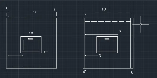
2 aim to draw the 3d view of the building
1 open autocad
2 select a new heet from the home rebbon
3 now select the units
4 draw a rec of 45.3 height and 6 breath
5 draw window by using the using the rec and offset option
6 now draw the other windows by following the dimentions
7 use m text and dim command to give the diamentions
8 result 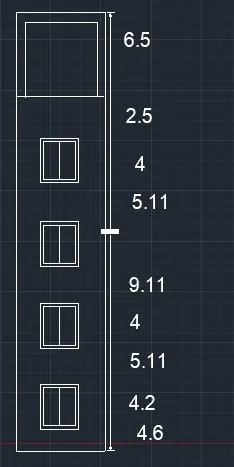
3 aim to draw a window with specificatins
procedure
1open autocad
2 select a new heet from the home rebbon
3 now select the unit
4 now draw a rec of 3,4
5 now give it a offset of 2
6 inow from the inner rec drw another rec by giving a offset of 3
7 now div the rec into two parts
8 result 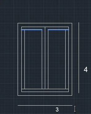
4 aim to draw the isometric view of the staircase
.
1open autocad
2 select a new heet from the home rebbon
3 now select the unit
4 now select a point
5 dra a line of 6
6 then draw a line of 1.5
7 repeat this proceess to draw multiple steps
8 then draw a line of 3 at the end of steps as landing now
9 join the 1t step base with the landing
10 now draw a line of 3.2 on the top of the firse setp and give it a ofset
11 now copy that stair holder on all the steps
12 no go the snapoption and select the end points
13 use the line option to join the lines
15 result 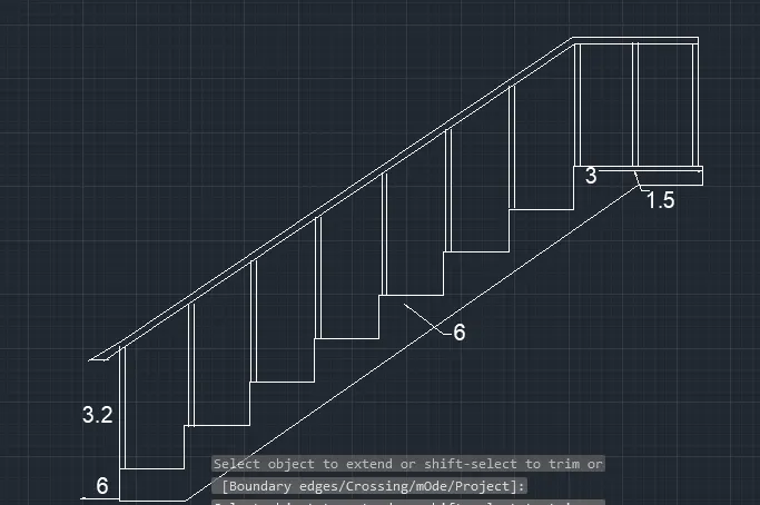
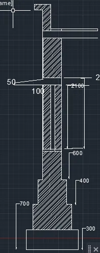
6 aim to draw the isometric view of wall footing
1 open autocad
2 select a ne sheet
3 now select units and limits
4 now draw the 1 se rec and on top of 2 rec wit the use of proper dimention
5 now draw another rec and give it a offst from both sides to make two rec
6 now draw a extended section with the help of lline and trim command
7 now use the hatch command to hatch the parts
8 use the leader option to specify the dimentions
9