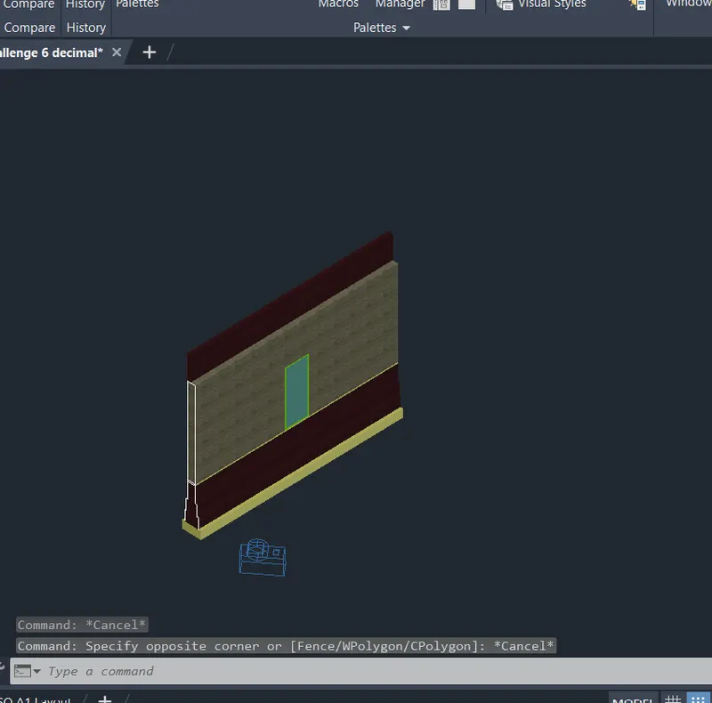
Creating 3D Isometric view of various structural elements in AutoCAD
1.Aim: To create the 3d model of building unit in the Auto cad engineering system.
- Auto Cad 3d modeling is developed to plot the modules in 3 dimensional or as to develop the solind model of a unit.
- In Auto cad length ,width and height is also plotted in the same plane. In the auto acd 2d Only one plane formed with X and y axis is only used while in the Auto cad 3d model Z axis is also used to plot the height of the model with repect to the X and Y axis.
- In the Auto cad 3d model all the views of the model can be visible simultaneously using the view cube option.
Procedure:
- Click on new File and create the new template for plotting the drawing
- Now enter units (un) command and select the engineering system in the units and also set the precision of the units and insertion scale to inches and click on ok.
- Now click on the settings and change the model space from the drafting and annotation to the 3d modeling.The 3d modeling ribbon bar with various 3d tool bars is updated in the ribbon.
- Now click on the view cube to change the UCS icon in to the various views as we required.
- Now click on the view cube and set the ucs icon in to the desired plane and the model is plotted on the selected plane of the axis.
- The given plan is a wall of the building which can be plotted with the poly line command or rectangle command.Enter the recangle command and plot the rectangle to a size of 10'9"x10'9".
- Enter the off set command and offset the rectangle to an offset distance of 9" and trim the line on two sides in which the wall section isnot shown in the plan.
- Now enter the poly line command and plot the window on the walls to a size of 3'.
- Now create the layers for the wall and the window using the layer command.
- Now enter the region in the command bar and create the regions for the walls in the plan or the regions can be created by the boundry command by selecting the closed boundry area.
- The unit is extrude with an desired thickness for the making as a solid unit.The extrude command will be worked only for the units which are created with the regions only.
- Now eneter the extrude command in the command bar and select the region of the wall and enter the dis tance to which the wall is to be extruded and press enter then the model is extruded to the required thickness and formed as a solid model.
- First extrude the wall in the downward direction to a thickness of 4" whuch will be the dampproof course or any other unit below the walls and again enter the extrude command in the command bar and extrude the walls in the upward direction to a height of 10'.
- Now enter the rectangle comman and plot the rectangle over the window and create the region for the rectangle over the window and enter the extrude command and extrude the rectangle over the window to the sill level of window which is 3' from the bottom of the wall.
- Now again enter the rectangle command and plot the recagle of size 3'x4' which equal to the window size and offset the rectangle to a thickness of 3" which create the frame of the window and again offset the rectangle to an offset distance of 4" which create the panel of the window.
- Now create the region for the frame and panel of the window and create the layers for the frame and panel of the window.The frame of the window is extrude to the inside of the wall using the extrude command to a distance 2".
- Now change the ucs icon to the top face and plot the rectangles over the walls to asize of 10'9"x9" and create the regions for the rectangles using the region or boundry command and extrude the rectangles over the walls to a thickness of 6" which may be the slab of the building.
- Now change the drawing in to shaded option and we can get the isometric model of the building and after the rendering of the plot is created if we require.
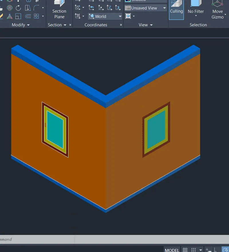
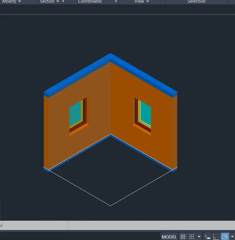
- The result of the 3d model of the building unit is obtained as shown below.
2.Aim: To create the 3d model of building unit in the Auto cad engineering system.
- Auto Cad 3d modeling is developed to plot the modules in 3 dimensional or as to develop the solind model of a unit.
- In Auto cad length ,width and height is also plotted in the same plane. In the auto acd 2d Only one plane formed with X and y axis is only used while in the Auto cad 3d model Z axis is also used to plot the height of the model with repect to the X and Y axis.
- In the Auto cad 3d model all the views of the model can be visible simultaneously using the view cube option.
Procedure:
- Click on new File and create the new template for plotting the drawing
- Now enter units (un) command and select the engineering system in the units and also set the precision of the units and insertion scale to inches and click on ok.
- Now click on the settings and change the model space from the drafting and annotation to the 3d modeling.The 3d modeling ribbon bar with various 3d tool bars is updated in the ribbon.
- Now click on the view cube to change the UCS icon in to the various views as we required.
- Now click on the view cube and set the ucs icon in to the desired plane and the model is plotted on the selected plane of the axis.
- The given plan is a wall of the building which can be plotted with the poly line command or rectangle command.Enter the recangle command and plot the rectangle to a size of 10'9"x6'9".
- Enter the off set command and offset the rectangle to an offset distance of 9" and trim the line on two sides in which the wall section isnot shown in the plan.
- Now enter the poly line command and plot the window on the walls to a size of 3'.
- Now create the layers for the wall and the window using the layer command.
- Now enter the region in the command bar and create the regions for the walls in the plan or the regions can be created by the boundry command by selecting the closed boundry area.
- The unit is extrude with an desired thickness for the making as a solid unit.The extrude command will be worked only for the units which are created with the regions only.
- Now eneter the extrude command in the command bar and select the region of the wall and enter the dis tance to which the wall is to be extruded and press enter then the model is extruded to the required thickness and formed as a solid model.
- It is multi storey building so we can plot the one floor and the rest of the floors can be copied with reference to the basepoint First extrude the wall in the upward direction to a height of 9'11".
- Now enter the rectangle command and plot the rectangle over the window and create the region for the rectangle over the window and enter the extrude command and extrude the rectangle over the window to the sill level of window which is 3'6" from the bottom of the wall.
- Now again enter the rectangle command and plot the recagle of size 3'x4' which equal to the window size and offset the rectangle to a thickness of 2" which create the frame of the window and again offset the rectangle to an offset distance of 3" which create the panel of the window.
- Now create the region for the frame and panel of the window and create the layers for the frame and panel of the window.The frame of the window is extrude to the inside of the wall using the extrude command to a distance 2".
- Now change the ucs icon to the top face and plot the rectangles over the walls to asize of 10'9"x9" and create the regions for the rectangles using the region or boundry command and extrude the rectangles over the walls to a thickness of 6" which may be the slab of the building.
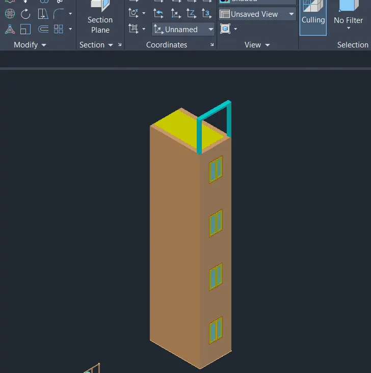
- The remaining floors canbe copied with reference to the bottom base point and the top unit is formed with the rectangle or the poly line command. Enter the rec command and plot the rectangle of size 4"x9" and extrude it to a height of 6'5" and copied it to edges of the wall and they are joined with rectangle and it also extruded to a thickness of 4"
- Now change the drawing in to shaded option and we can get the isometric model of the building and after the rendering of the plot is created if we require.
- The result of the 3d model of the building unit is obtained as shown below.
3.Aim: To create the 3d model of the stair case unit in the Auto cad engineering system.
- Auto Cad 3d modeling is develope9d to plot the modules in 3 dimensional or as to develop the solind model of a unit.
- In Auto cad length ,width and height is also plotted in the same plane. In the auto acd 2d Only one plane formed with X and y axis is only used while in the Auto cad 3d model Z axis is also used to plot the height of the model with repect to the X and Y axis.
- In the Auto cad 3d model all the views of the model can be visible simultaneously using the view cube option.
Procedure:
- Click on new File and create the new template for plotting the drawing
- Now enter units (un) command and select the engineering system in the units and also set the precision of the units and insertion scale to inches and click on ok.
- Now click on the settings and change the model space from the drafting and annotation to the 3d modeling.The 3d modeling ribbon bar with various 3d tool bars is updated in the ribbon.
- Now click on the view cube to change the UCS icon in to the various views as we required.
- Now click on the view cube and set the ucs icon in to the desired plane and the model is plotted on the selected plane of the axis.
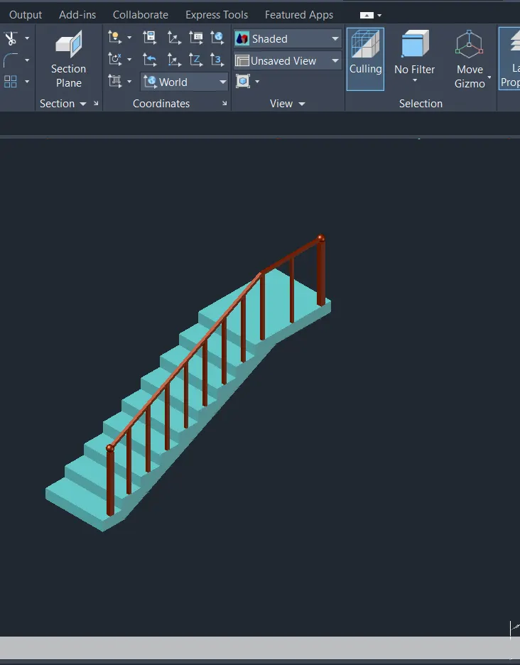
- The given plan is a stair case of the building with the hand rail which can be plotted with the poly line command or rectangle command.The stair case is generraly developed with the elevation model drawing and it can be plotted with a poly line command
- Enter the polyline command and plot the step of tread size 1' and size of rise is 6" One step is plotted and the remaining steps are copied with refence ot previous step.
- Now enter the copy in the command bar and select the step and press enter and then select array inthe command bar and enter the number of steps as 9 nos and press enter
- The landing at the top of the flight plotted with line command to a width of 3' and enter the line command and join the stps in the bootom of the flight and offset the line to an offset distance of 6" which forms the soffit slab of the stair case.
- Now the stair case is formed as a region and it is rotated with the 3d command with an angle of 90 and it is extruded to a distance of 3'.
- The balustrades is plotted on the step with the rectagle command of size 2"x2" and it extruded to a height of 3' and it is copied to all the steps and all the ballustrade is joined with line and it sweep with the rectangle which forms the hand rail of the stair case.
- The hand rail is copied ot other side of the flight and layers are inserted to the steps and the hand rails.The drawing mode is changed to the 2d wire frame to the solid editting model.
- The result of the 3d model of the stair case unit is obtained as shown below.
4. Aim: To create the 3d model of the wall with a spread footing unit in the Auto cad decimal system.
- Auto Cad 3d modeling is developed to plot the modules in 3 dimensional or as to develop the solind model of a unit.
- In Auto cad length ,width and height is also plotted in the same plane. In the auto acd 2d Only one plane formed with X and y axis is only used while in the Auto cad 3d model Z axis is also used to plot the height of the model with repect to the X and Y axis.
- In the Auto cad 3d model all the views of the model can be visible simultaneously using the view cube option.
Procedure:
- Click on new File and create the new template for plotting the drawing
- Now enter units (un) command and select the decimal system in the units and also set the precision of the units and insertion scale to mm and click on ok.
- Now click on the settings and change the model space from the drafting and annotation to the 3d modeling.The 3d modeling ribbon bar with various 3d tool bars is updated in the ribbon.
- Now click on the view cube to change the UCS icon in to the various views as we required.
- Now click on the view cube and set the ucs icon in to the desired plane and the model is plotted on the selected plane of the axis.
- The given plan is a wall of the building with the spread footing which can be plotted with the poly line command or rectangle command.Enter the recangle command and plot the rectangle to a size of 700x300 which will be the bottom raft of the footing.
- Now again enter the poly line command and create the footing of three steps of size 500x400,400x400, 300x600 and the wall to the size of 300x3300.
- Now create the layers for the wall and the footing steps separately using the layer command.
- Now enter the region in the command bar and create the regions for the walls in the plan or the regions can be created by the boundry command by selecting the closed boundry area.
- The unit is extrude with an desired thickness for the making as a solid unit.The extrude command will be worked only for the units which are created with the regions only.
- Now eneter the extrude command in the command bar and select the region of the wall and enter the dis tance to which the wall is to be extruded and press enter then the model is extruded to the required thickness and formed as a solid model.
- The footing and the wall is of same length 7500 so the footing and the wall can be extruded to a distance of 7500. Now eneter the rec command and create the rectangle of size 900x2100 in the wall at a distance of 3300 from one of edge of the wall and it formed as a region and extruded to thickness of 300 and it is subracted from the wall so thet we can insert the door easily.
- The door can be plotted on the wall using the rectangle command and to a size of 900x2100 and the frame and panel is created with offset command to an offset distance of 50mm and 75mm.
- Now create the region for the frame and panel of the window and create the layers for the frame and panel of the window.The frame of the window is extrude to the inside of the wall using the extrude command to a distance of 50mm.
- The parapet wall is plotted with a polyline command and a coping of 50x50mm is created with same polyline and it extruded to the length equal to the wall.
- Now the drawing is rendered to get the desired view of the building wall.Rendering is the process of making the buiding view with various background and light and applying the material effects first change the drawing mode in to the realistic mode and enter the camera in the command bar and place the camera at the required altitude and enter the details of the lens of the camera and press enter.
- Now select the material browser apply the various materials of the building unit and assign the material unit accprding to the desire and the model is saved.
- The result of the 3d model of the wall with the spread footing unit is obtained as shown below.