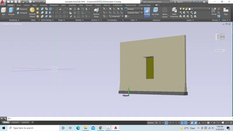
Creating 3D Isometric view of various structural elements in AutoCAD
1. 3D isometric view of building
To create the isometric view of the given building
Steps
- Draw the floor plan, elevation of the building with given dimension
- Create the layer such as 3d wall, 3d window frame, 3d mulions etc
- Select the wall in floor plan by using the command boundary create the region inside the boundary
- Then use subtract command to subtract the inner region
- Create the windox frame, mulions and glass by using the command boundary adn subtract
- Then extrude the regions at specified dimensions
Result
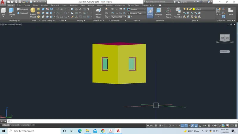
3. 3D isometric view of building
To create the isometric view of the given building
Steps
- Draw the floor plan, elevation of the building with given dimension
- Create the layer such as 3d wall, 3d window frame, 3d mulions etc
- Select the wall in floor plan by using the command boundary create the region inside the boundary
- Then use subtract command to subtract the inner region
- Create the windox frame, mulions and glass by using the command boundary adn subtract
- Then extrude the regions at specified dimensions
Result
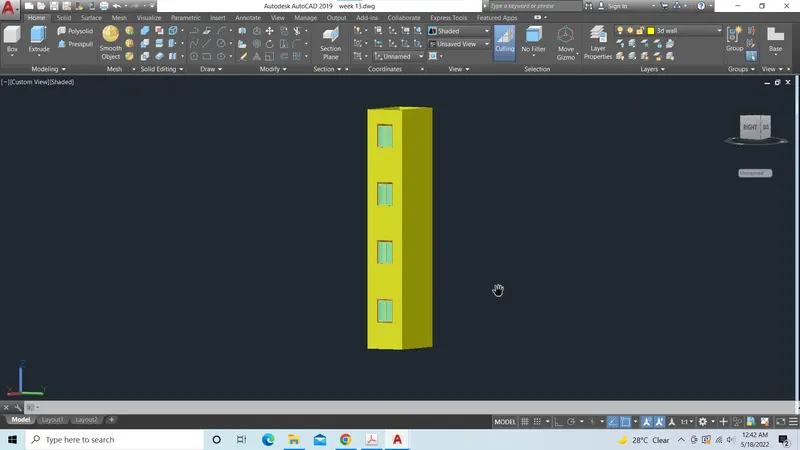
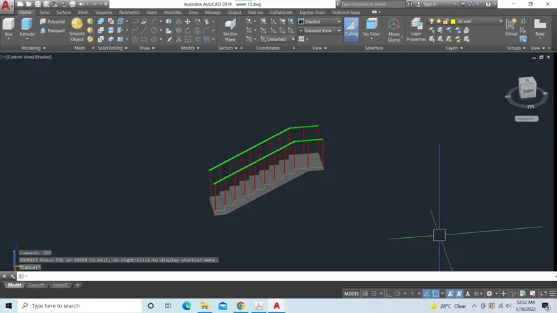
4. 3D isometric view of stair case
To create the isometric view of the given building
Steps
- Draw the floor plan, elevation of the staircase with given dimension
- Create the layer such as 3d stairs, 3d hand rails, 3d hand rail frames etc
- Select the stairs in floor plan by using the command boundary create the region inside the boundary
- Then extrude the stairs in 90 in y direction to 3'
- Then draw circle of radius 1'' at 2'' distance from both x and y direction then extrude to cylinders in z axis of distance 2'8
- Then copy the cylinders to all stairs
- Then change ucs icon, draw the circle of 2'' over the cylinders and create region by using boundary command
- Then extrude the handrail by using the path line created by connecting the centres of the cylinders
Result
5. 3D isometric view of wall footing
To create the isometric view of the given building
Steps
- Draw the plan, section view of the wall footing with given dimension
- Create the layer such as 3d wall, 3d door frame, 3d door, 3d lintel etc
- Select the wall in floor plan by using the command boundary create the region inside the boundary
- Similarly select the footing and create region for footing
- Then create door region, door frame region from the section drawing
- Then use subtract command to subtract the inner region
- Then extrude the regions by using the dimensions given in the drawing.
- Then open material browser in view ribbion
- Then pick material such as wall paint(light beige), wood (laquared, robble) for door and door frame and concrete (wall texture - beige) for footing
- Then assign the materials
Result