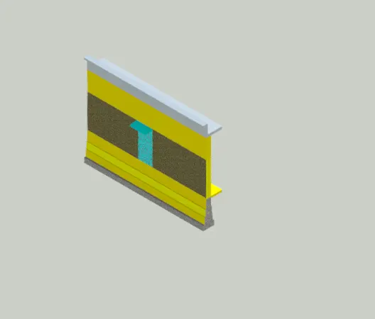
Creating 3D Isometric view of various structural elements in AutoCAD
Aim - To create a 3D Isometric view of building with plan and elevation.
Introduction - i) An Isometric view is an 3D representation of the object.
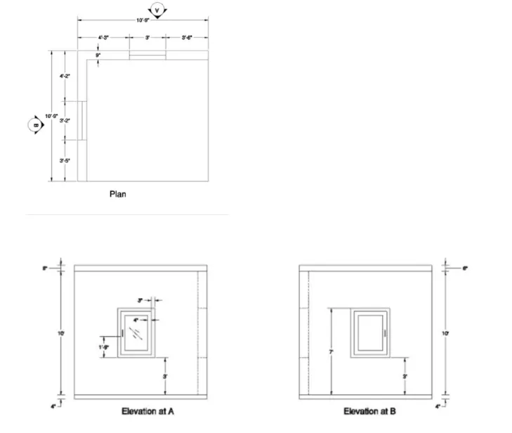
ii) In an give fig , view of building is given with plan and elevations.
iii) Height of the building is given as 10' .
iv) The thickness of bottom and top floor is given as 4" and 6"
v) Following Commands are used -
a) Line
b) Rectangle
c) Extrude
d) 3DMove
e) Copy
f) Dim
g) 3D faces
h) Region
i) Subtract
j) Boundary
Procedure -
i) Open a New drawing (Cntrl + N) select Imperical units ( Feet and Inches )
ii) Select units to Engineering and select precision as Inches (0'0.0")
iii) Command DS / Drafting settings - Change the Snap spacing and Grid spacing 1' and Change major lines
every grid to 5 .
iv) Change the workspace setting from Drafting and Annotations to 3D Modeling .
Step by Step Procedure -
Step 1) Creating a plan
i) To draw a rectangle
ii) Command Rec
iii) Enter Length - 10'10"
iv) Enter Width - 10'10"
v) Command Offset - Take the offset of 9" to draw the wall thickness .
vi) Now we have to draw the windows on upper side and left hand side of size 3' and 3'2" respectively .
vii) Command DIM linear and measure the dimensions as per given drawing .
viii) On view cube click on TOP view .
Step 2)
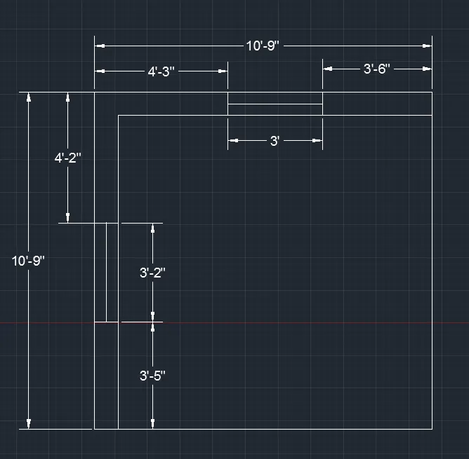
i) Now we have to create boundary to extrude the wall
ii) Command Boundary
iii) Pick up the points , pick up the edges of the wall , Press Enter
iv) Command Extrude
v) Extrude the object at an ht of 10'10" .
vi) Extrude the window at height of 3'4" using the Extrude command .
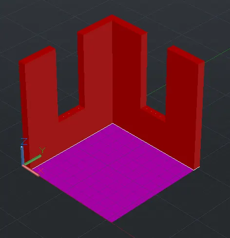
vii) Now , draw a rectangle at the top to draw a window opening on both the side
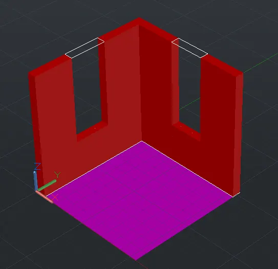
ix) Command boudary
x) Pick up the point of rectangle which we have drawn
xi) Exclude the rectangle to the downward side 3'6"
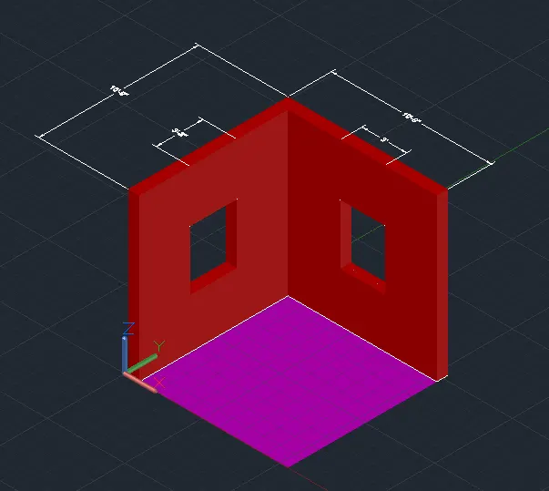
Step 3) Create Elevations A and B
i) Create a rectangle
ii) Command Rec 1
iii) Enter Length - 3'
iv) Entter Width - 4'
v) Enter Length - 3'2"
vi) Entter Width - 4'
vii) Create an offset of a distance 3" and again 4" for both the window
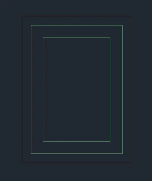
vi) Command Subtract - Select bigger region and subtract smaller region
vii) Follow the same procedure for all the three boxex.
viii) Command BO
ix) Pickup the internal points and press Enter .
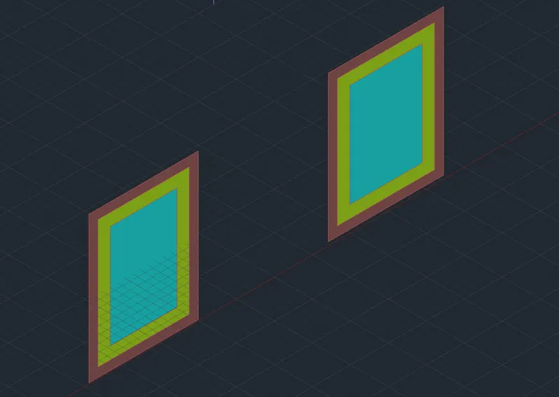
Step 4)
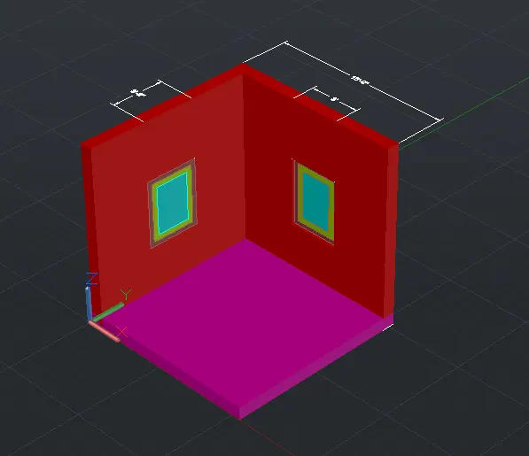
i) Command 3DMove
ii) Move the window and assign it to the respective opening of 3' and 3'2"
Step 5)
i) To see the different view click on view cube and select the view
ii) Click on View on Ribbon bar and Create a new view as V1
iii) Similarly we can create different views by creating a view or directly from the view cube.
Step 6)
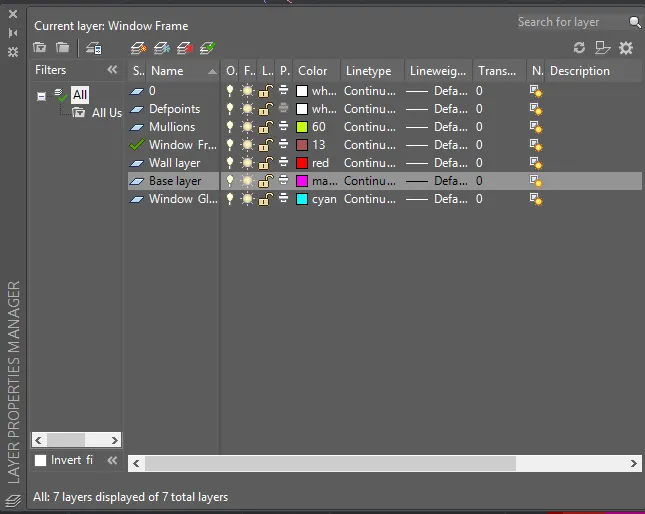
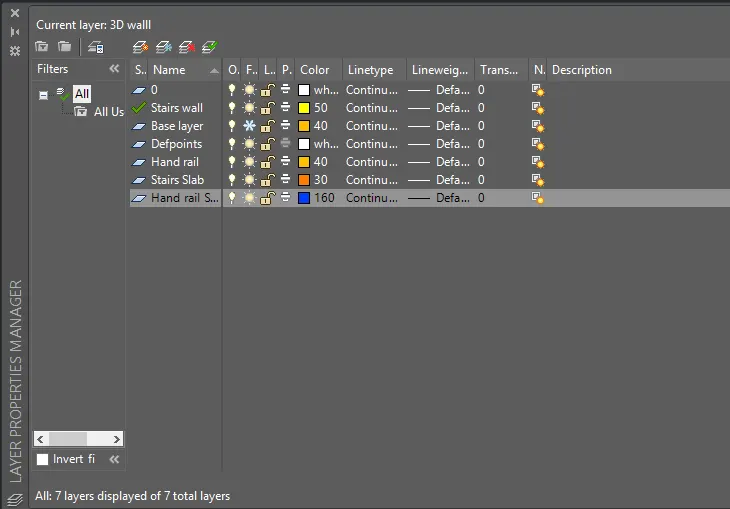
i) Command Layer
ii) We have already create a different layer by giving different properties
iii) Following are the layers which are used .
Results -
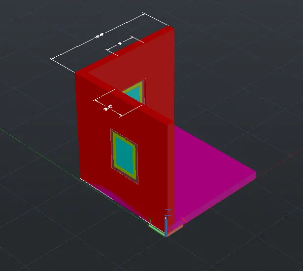
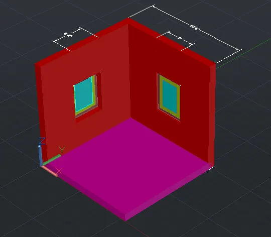
i) A 3d Isometric View of Building is created with given plan dimensions and given elevations.
ii) Following are the 3D views .
1) SW ISOMETRIC -
2) SE ISOMETRIC -
3) NE ISOMETRIC -
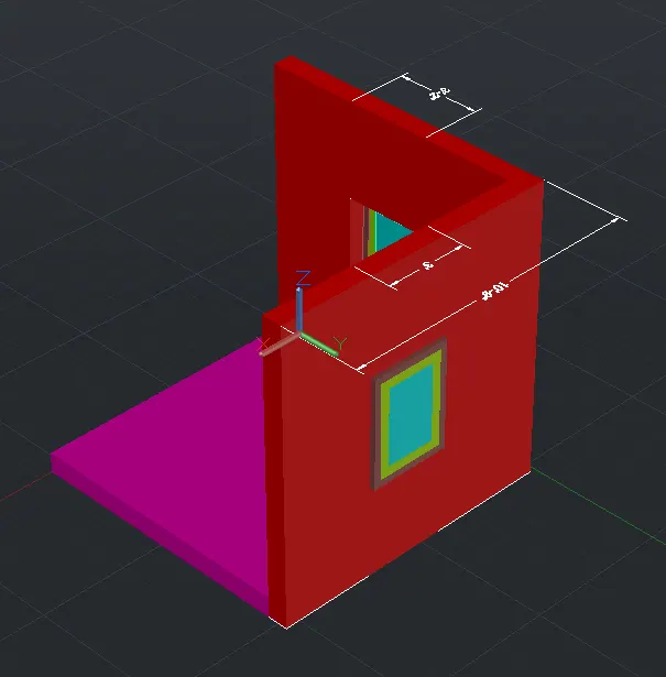
4) ELEVATIONS A and ELEVATIONS B -
2)
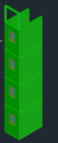
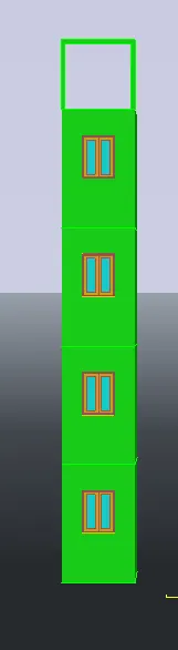
Aim - To create 3D View of the Building Façade as given in the plan and elevation.
Introduction - i) In a given fig a 3D view of building facade is given with plan and elevations
ii) Dimensions are given in fig .
iii) Floor to floor height is given as 5'11"
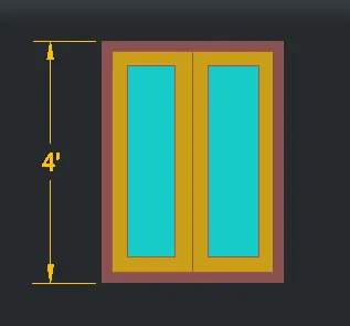
iv) Height of window is given as 4'6" .
v) Following Commands are used -
a) Line
b) Rectangle
c) Extrude
d) 3DMove
e) 3D Rotate
f) Copy
g) Dim
h) 3D faces
i) Region
j) Subtract
k) Boundary
Procedure -
i) Open a New drawing (Cntrl + N) select Imperical units ( Feet and Inches )
ii) Select units to Engineering and select precision as Inches (0'0.0")
iii) Command DS / Drafting settings - Change the Snap spacing and Grid spacing 1' and Change major lines
every grid to 5 .
iv) Change the workspace setting from Drafting and Annotations to 3D Modeling .
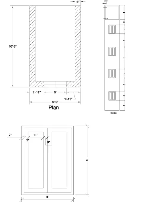
Step by Step Procedure -
Step 1) Create a layer
i) Command LA
ii) Create a different layer by adding new layer .
iii) Following are the layers
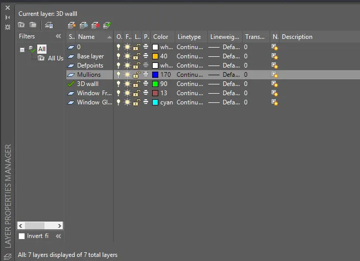
Step 2) Create a plan -
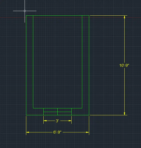
i) Create a plan of 6'9" x 10'9"
ii) Command Rec
iii) Enter length - 6'9"
iv) Enter width - 10'9"
v) Command Offset - 9" for wall
v) Draw a window of size 3' as shown in fig
vi) Command DIm and measure the dimensions
Step 2) Create a wall
i) Command BO
ii) Pick up the internal points
iii) And Press Enter - Region is created
iv) Command Extrude and And extrude the wall at a height of 10'10"
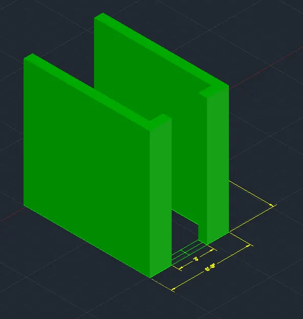
v) Now we have to create a window openings , for that we have to create a rectangle where we have drawn window opening
vi) Extrude the window at a height of 4'6" .
vii) Draw the rectangle at top and Extrude it at bottom at height of 1'3"
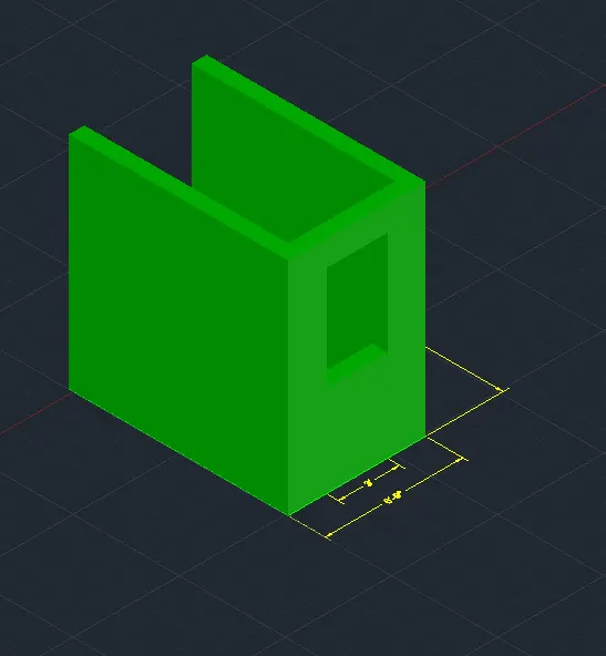
Step 3) Create a window
i) Create a window of size 3' x 4'
ii) Command Rec
iii) Enter length - 3'
iv) Enter width - 4'
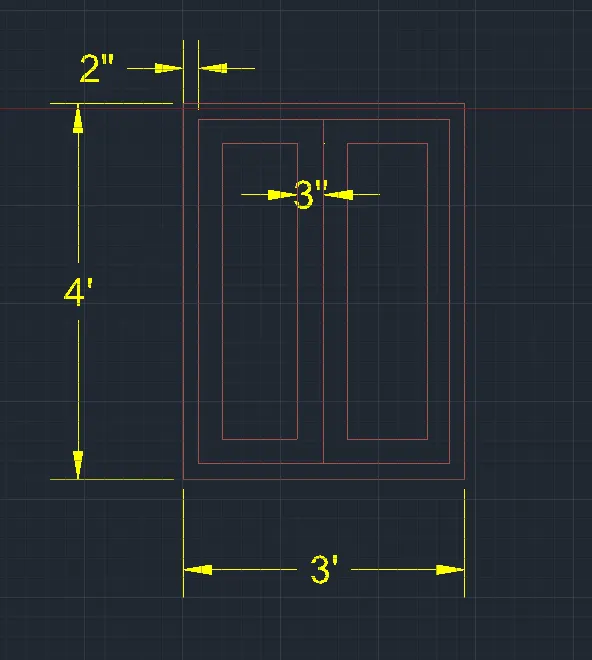
v) Command Bo
vi) Pick up the internal points and press Enter .
vii) Similarly we have to do it for remaining boxex also
viii) Command Subtract - Select Biggere rectangle and subtract smaller rectangle .
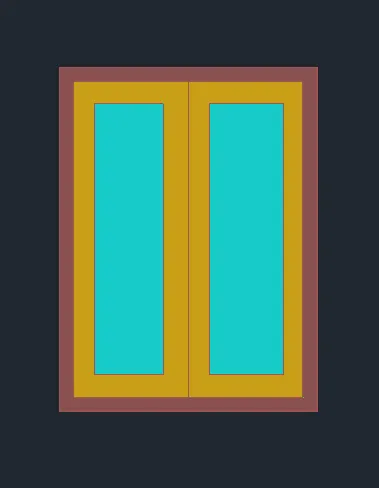
ix) Command 3D move
x) Move the windows to the openings and place it .
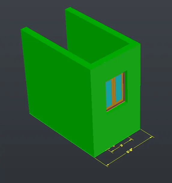
Step 4) Elevations
i) Command Copy
ii) Copy the 1st floor to 4 times as shown in fig
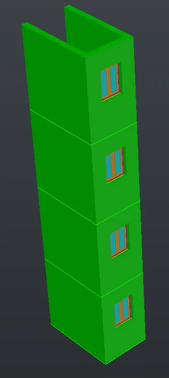
Step 5) Create top part
i) Command Rec
ii) Enter length - 6'9"
ii) Enter Width - 6'5"
iii) Command Offset of 4" to create a wall
v) Command boundary - Pick up internal points and Press Enter
vi) Command Extrude - at a distance of 9" as shown in fig .
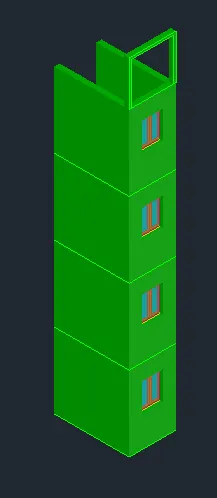
Step 6) To see the different views
i) To see the different view click on view cube and select the view
ii) Click on View on Ribbon bar and Create a new view as V1
iii) Similarly we can create different views by creating a view or directly from the view cube.
Results -
i) A 3D view of Building is created with plan and Elevations
ii) Following are the views
1) SW ISOMETRIC
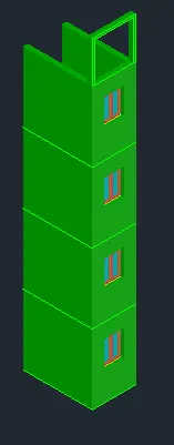
2) SE ISOMETRIC
3) Front View
4) Window Elevation
3)
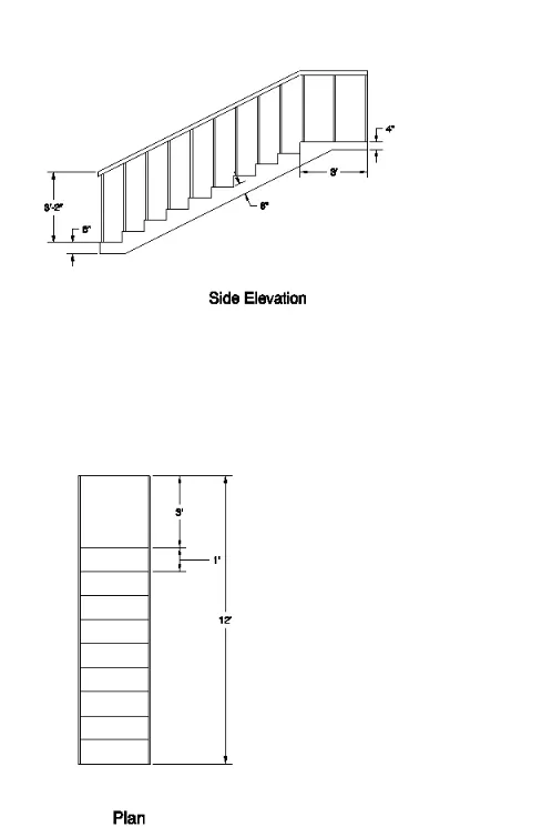
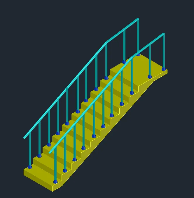
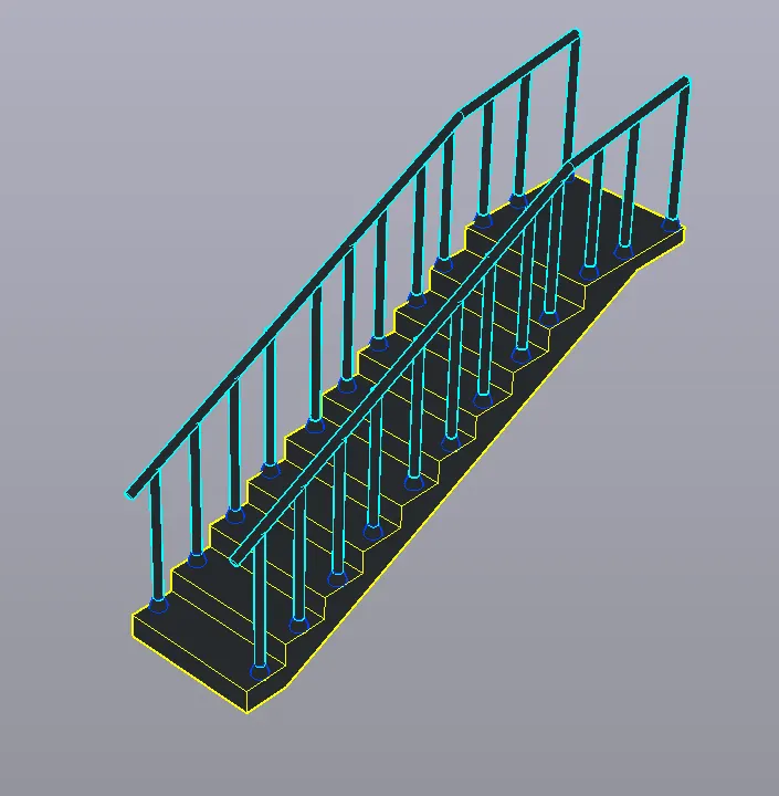
Aim - To create the 3D view of Staircase with railing as shown in fig .
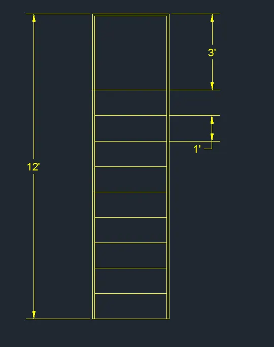
Introduction - i) A plan and elevations are given in figure .
ii) In a given plan 9 no of stairs are given
iii) Width of landing is given as 3'
iv) Tread is given as - 1' and Riser is given as 6"
v) Following Commands are used -
a) Line
b) Rectangle
c) Extrude
d) 3DMove
e) Copy
f) Dim
g) 3D faces
h) Region
i) Subtract
j) Boundary
k) Sweep
Procedure -
i) Open a New drawing (Cntrl + N) select Imperical units ( Feet and Inches )
ii) Select units to Engineering and select precision as Inches (0'0.0")
iii) Command DS / Drafting settings - Change the Snap spacing and Grid spacing 1' and Change major lines
every grid to 5 .
iv) Change the workspace setting from Drafting and Annotations to 3D Modeling .
Step by Step Procedure -
Step 1) Create a Layer
i) Command LA
ii) Create a layer with different properties as shown in figure .
iii) Following are the properties
Step 2) Create a plan
i) Command Rec
ii) Enter Length - 3'
iii) Enter Width - 12'
iv) Command Offset and take offset 1" on both sides
v) Again command offset and take distance 1' from bottom and repeat it for 9 times as shown in figure .
Step 3) Create a side elevation -
i) Command line
ii) Tak the reference point and draw a riser as 6" and draw thread as 1'
iii) Copy the 1st step and repeat it for 9 times
iv) From the last step draw the landings at a distance 3'
v) Draw a stairs slab of a distance 6" .
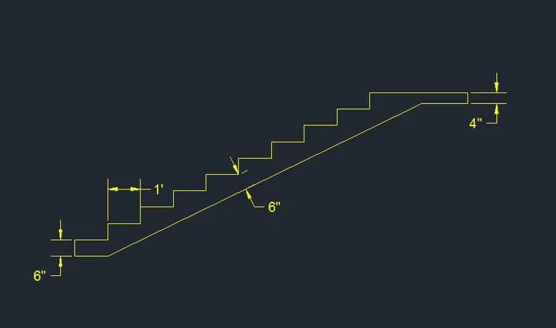
vi) Command BO
vii) Pick up the internal points and press Enter
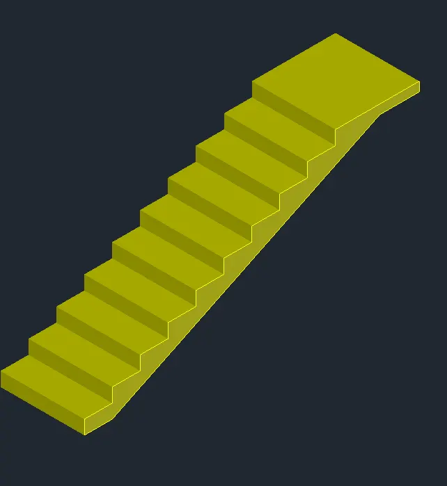
viii) Command Extrude - and extrude the side elevations at distance of 3' .
Step 4 ) Create a Hand rails
i) Create a Hand rails of 1" diameter at a height of 3'
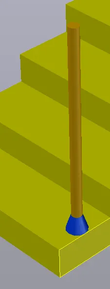
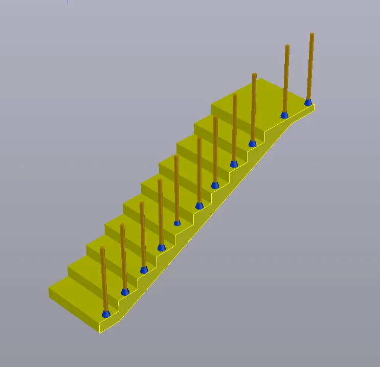
ii) Click on Front view and and copy the handrails on every steps .
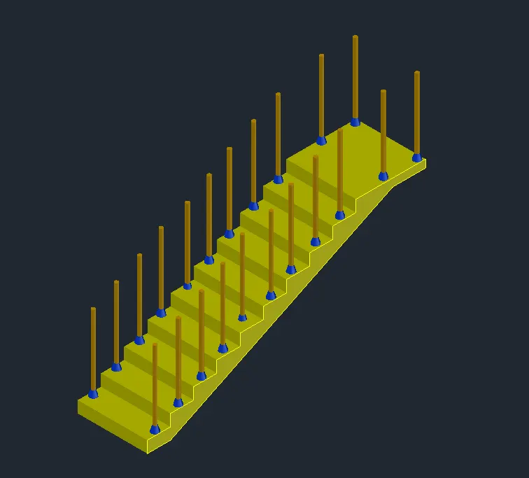
iii) Similarly copy this handrails on opposite also by giving command Copy .
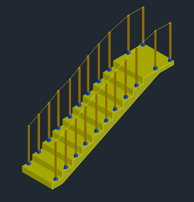
iv) Command Line
v) Join the top surface of hand rails by drawing the lines
vi) Command Circle
vii) Draw a circle of 1" Radius .
viii) Command Sweep and select the path as a the line which we have drawn in step (iv)
Step 5) To see the different views
i) To see the different view click on view cube and select the view
ii) Click on View on Ribbon bar and Create a new view as V1
iii) Similarly we can create different views by creating a view or directly from the view cube.
Results -
i) A 3D view of Staircase is created with plan and side elevations
ii) Following are the views .
1) SW ISOMETRIC
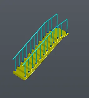
2) SE ISOMETRIC
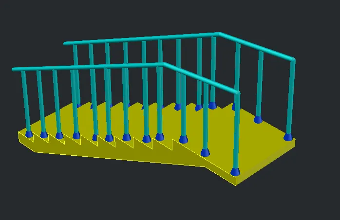
3) NW ISOMETRIC
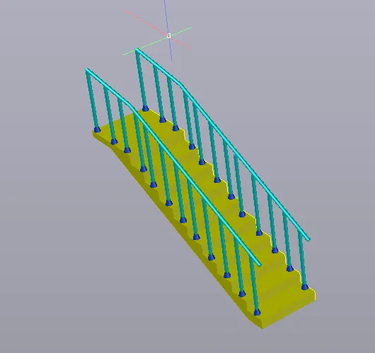
4) FRONT View
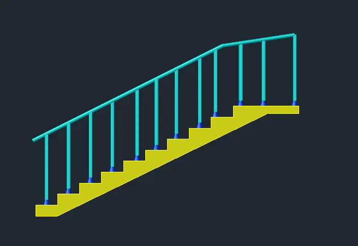
5) HIDDEN VIEW
4)
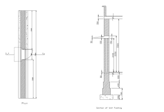
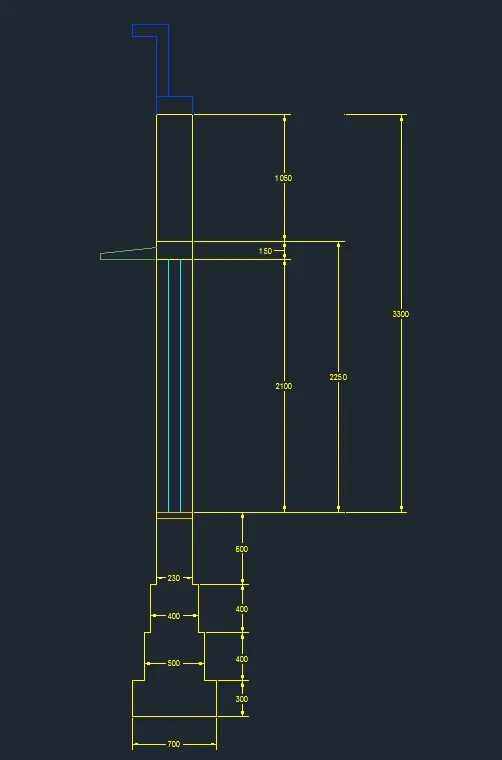
Aim - To draw a 3D view of wall with spread footing as shown in plan and section of wall footing .
Introduction - i) In a given fig , plan and section of wall is given which is having spread footing .
ii) Spread footing is type of shallow footing which is usually used under each column of building and piers .
iii) Thickness of wall is given as 230mm
iv) In section , detail dimension of footing is given .
v) Following Commands are used -
a) Line
b) Rectangle
c) Extrude
d) 3DMove
e) Copy
f) Dim
g) 3D faces
h) Region
i) Subtract
j) boundary
k) MAT
l) Render
Procedure -
i) Open a New drawing (Cntrl + N) select Imperical units ( Feet and Inches )
ii) Select units to Engineering and select precision as Inches (0'0.0")
iii) Command DS / Drafting settings - Change the Snap spacing and Grid spacing 1' and Change major lines
every grid to 5 .
iv) Change the workspace setting from Drafting and Annotations to 3D Modeling .
Step by Step Procedure -
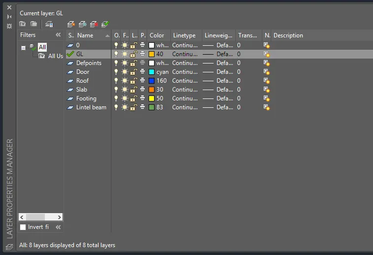
Step 1) Create a Layer
i) Command LA
ii) Create a layer with different properties as shown in figure .
iii) Following are the properties
Step 2) Create a plan
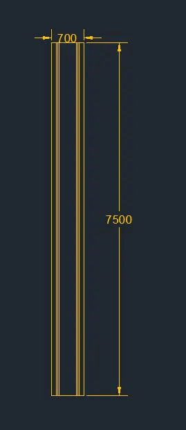
i) Create a plan of 700mm x 7500 mm
ii) Command Rec
iii) Enter Length - 700mm
iv) Enter Width - 7500mm
v) Command Offset
vi) Take the offset of 100 mm from left and right side
vii) Again take offset of 30mm , 30mm on both sides .
Step 3)
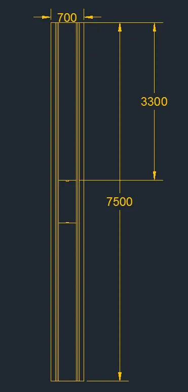
i) Draw a vertical line of distance 3300mm from botttom .
ii) From 3300 point draw a horizontal line and take the offfset of 900mm ( For Door )
iii) Measure the remaining distance it will be 3300 mm .
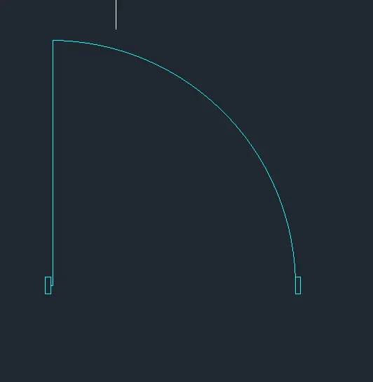
iv) Create a door
a) Draw a horizontal line of distance 900 mm
b) Draw a frame of 30mm x 20 mm
c) Draw a hinges by taking offset of 10 mm from frames .
d) Draw a circle by taking midpoint of hinges and draw the circle till it touches to the other sides
e) Trim the remaining lines .
v) Move the door to the plan .
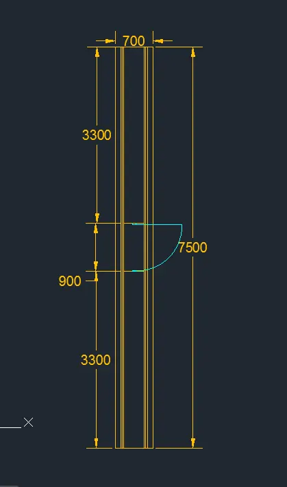
vi) Draw a section line as shown in fig
vii) Change the line type to ISO DASH type
viii) Command DT and Give the text as A A on both siides .
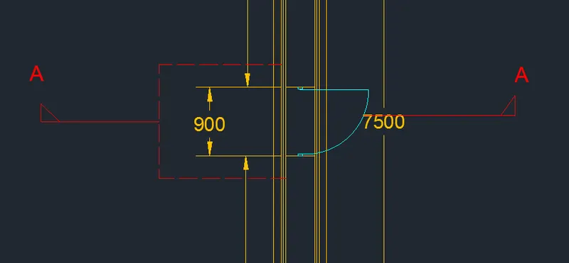
ix) Command Hatch -
x) Select the hatch pattern as AR - CONC
xi) Pickup the internal points and press enter
xii) Change the scale to 10 to visible hatch pattern
xiii)Similarly follow the same pattern for hatching of wall .
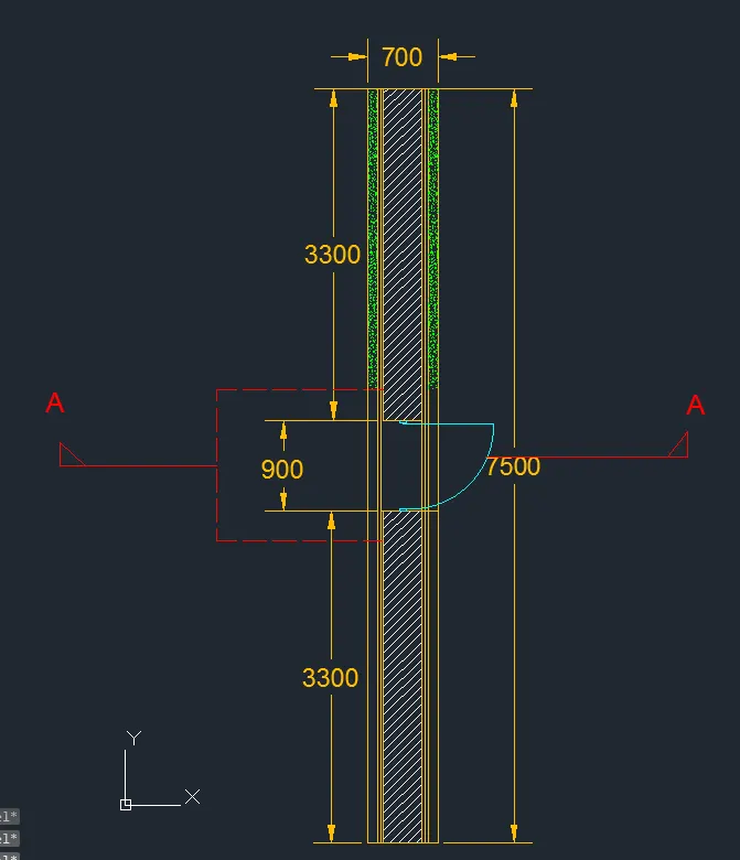
Step 4) Creating Section View of Wall .
i) Draw a PCC of size 700mm x 300mm
ii) Command Rec
iii) Enter length - 700 mm
iv) Enter width - 300 mm
v) Now we have to draw 1st step footing as a size of 500mm x 400mm
vii) Similarly draw 2nd stpe footing of size 400mm x 400mm
viii) Siimilarly draw 3rd Step footing as a size of 300mm x 600 mm
ix) From top take the offset of 50mm as shown in fig .
x) Trim unwanted lines
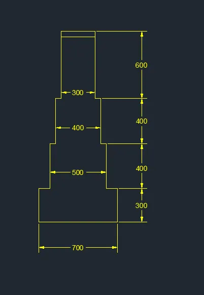
xi) Command Line - Draw a vertical line of 2100mm
xii) Again draw a line of 150mm
xiii) Again draw a line of 1050mm from previous line and close the line by drawing the same line on opposite side also
xiv) To draw a upper part take offset of 150mm from previous lines horizontlly .
xv) Draw a vertical line of a distance 500mm . Draw a horizontal line of 200mm in -x direction .
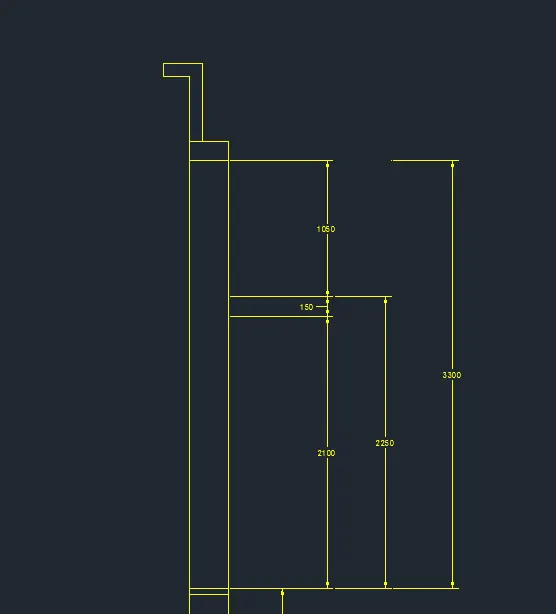
xvi) Draw lintel beam , door and assign layer respectively .
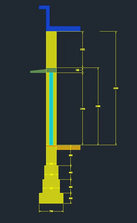
Step 5) Creating A 3D view -
i) First create a boundary layer
ii) Command Bo
iii) Pickup the intenal points
iv) Follow the same procedure for whole wall .
Step 6)
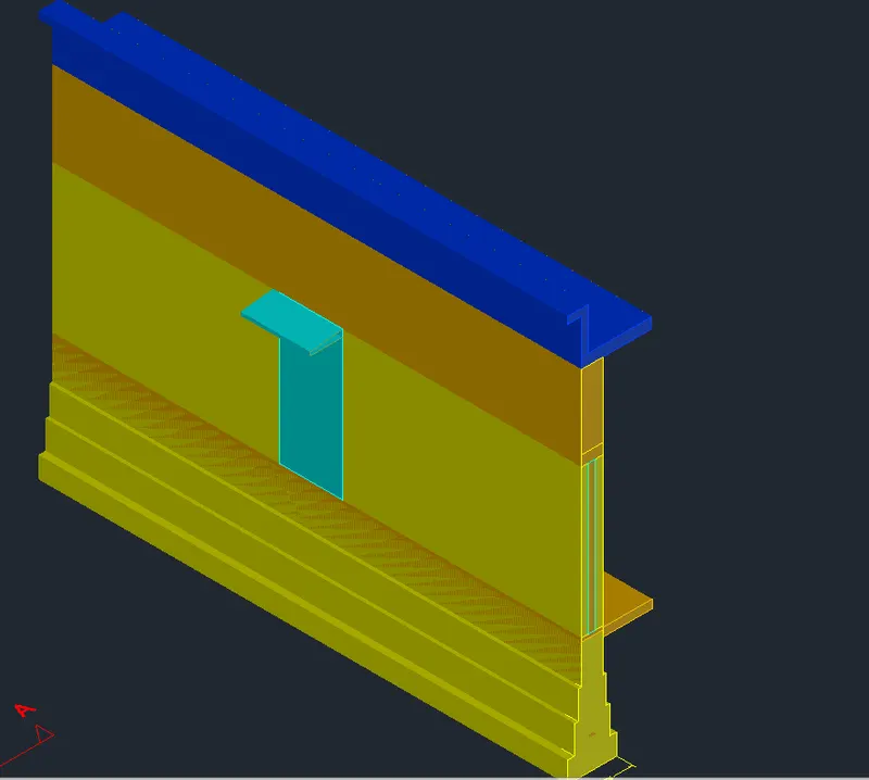
i) After creating 3D view , we have to extrude the region by 7500 mm
ii) Command Extrude
iii) Select the whole object and Extrude the region at a distance 7500 mm
iv) To draw a door - Command UCS - Select the face - set the ucs
v) Draw a door and Subtract it from the wall .
Step 7) To create Rendering view -
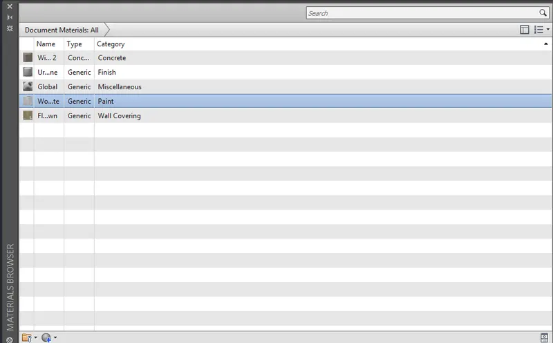
i) To create a render view 1st we have assign the material properties
ii) Command MAT - Add propertes
iii) Following are the properties .
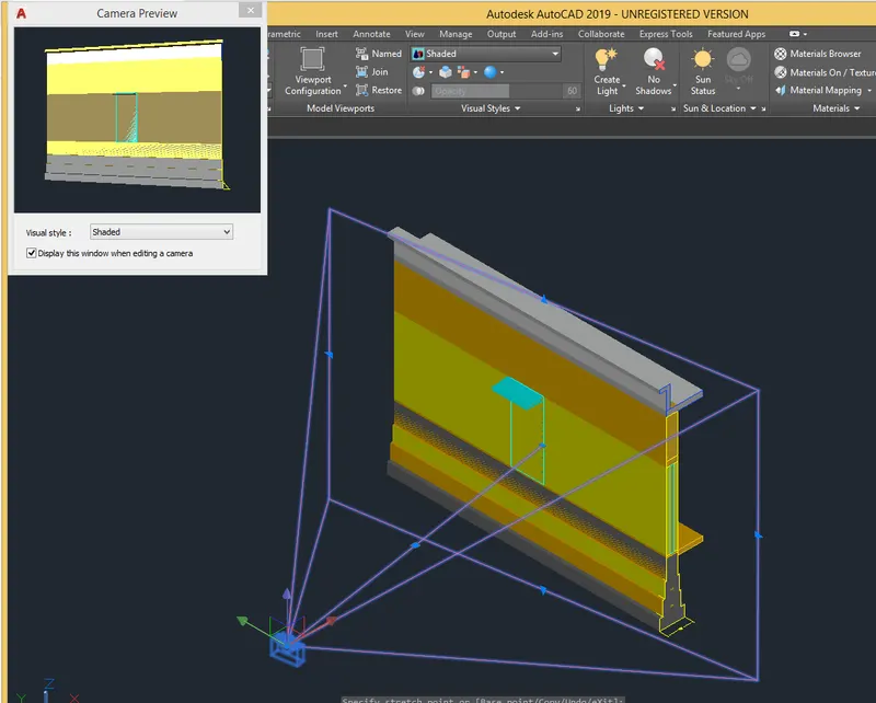
iii) Set a camera at a distance of 1000mm from door and at an height of 500mm from ground
Results -
i) A 3D view of wall with spread footing is created .
ii) A different material properties are assigned to the section
iii) A render view is also created .
1) Plan -
2) View of Spread Footing -
3) SE ISOMETRIC -
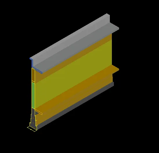
4) SW ISOMETRIC
5) Render View -