Creating 3D Isometric view of various structural elements in AutoCAD
1. Create a 3D Isometric View of the building with plan and elevation given.
Aim :-
- To Create a 3D Isometric View of the building with plan and elevation.
Introduction :-
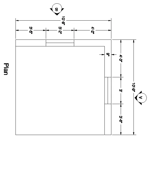
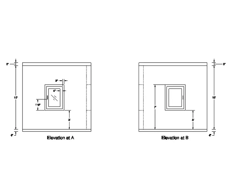
- A Plan view of 2 walls is given.
- There is separate window in both the walls.
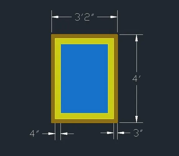
- Width of both the windows of A side and B side is 3' and 3'2" respectively.
- Window has 3" window Mullion and 4" of frame.
Procedure :-
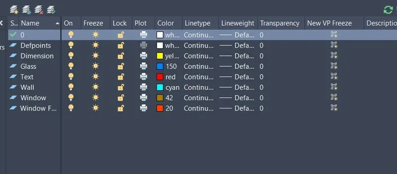
- Open Layer properties and create the different layers for the different components.
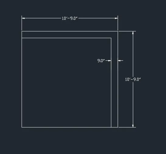
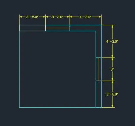
- Create a rectangle of size 10'9" X 10'9".
- Now offset the rectangle2 side lines with 9" as showing below in the image.
- Delete Unwanted Lines.
- Draw the line at the middle of the 9" upper side Wall.
- Offset the line with 1'7".
- Draw the line at the rightside wall of the 9" Wall.
- Offset the line with 1'6".
- Annotate with the dimension.
- Select the boundary command and select the boundary of the wall.
- Now select EXTRUDE command and Extrude the walls in upper side with the height of 10'.
- Select the boundary command and select the boundary of the window.
- Now select EXTRUDE command and Extrude the window in upper side with the height of 3'.
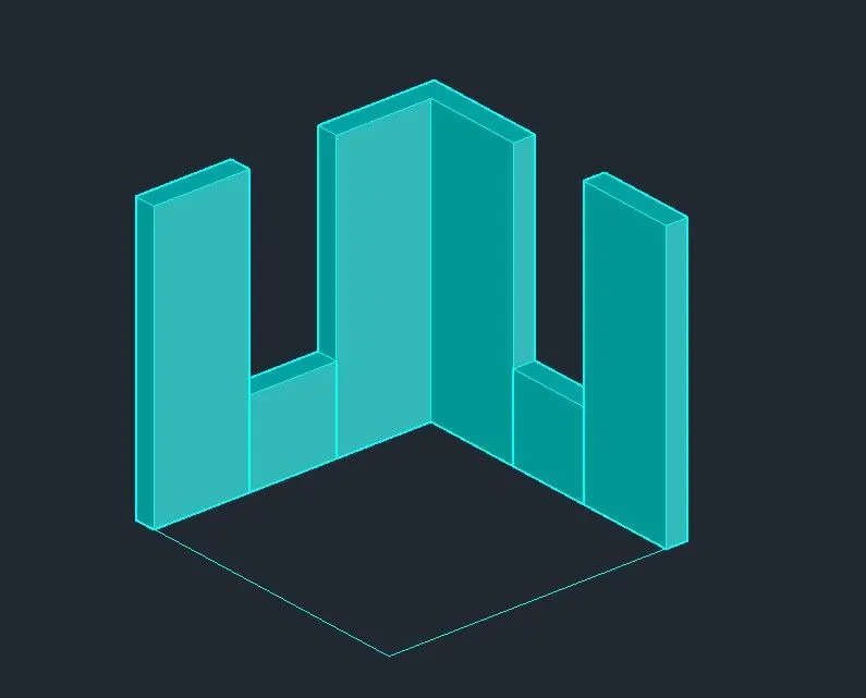
- Now draw the rectangle at the top side of the wall.
- Select the boundary command and select the boundary of the window.
- Now select EXTRUDE command and Extrude the window in upper side with the height of -4'.
- Select the Union command and select all the wall and press Enter.
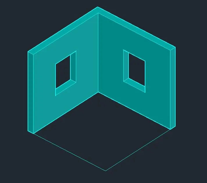
- Switch off the layer of walls.
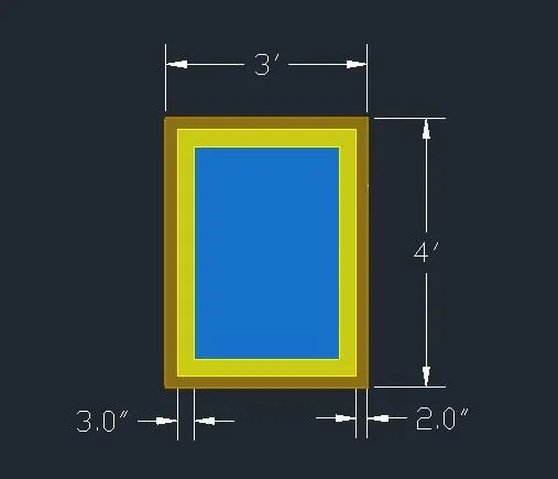
- For window of A side wall, Draw rectangle of 3' X 4'.
- offset the rec. 2" and 3" distance inside.
- Now select the Outer rectangle and type boundary command and pick the point.
- It will select whole window.
- Now substract the window frame.
- Do the same process for Window mullion and window glass.
- And add the layers in the Window.
- Extrude the winwow as per the width of wall.
- For window of B side wall, Draw rectangle of 3'2" X 4'.
- offset the rec. 3" and 4" distance inside.
- Now select the Outer rectangle and type boundary command and pick the point.
- It will select whole window.
- Now substract the window frame.
- Do the same process for Window mullion and window glass.
- And add the layers in the Window.
- Extrude the winwow as per the width of wall.
- Now Swith on the layer of wall.
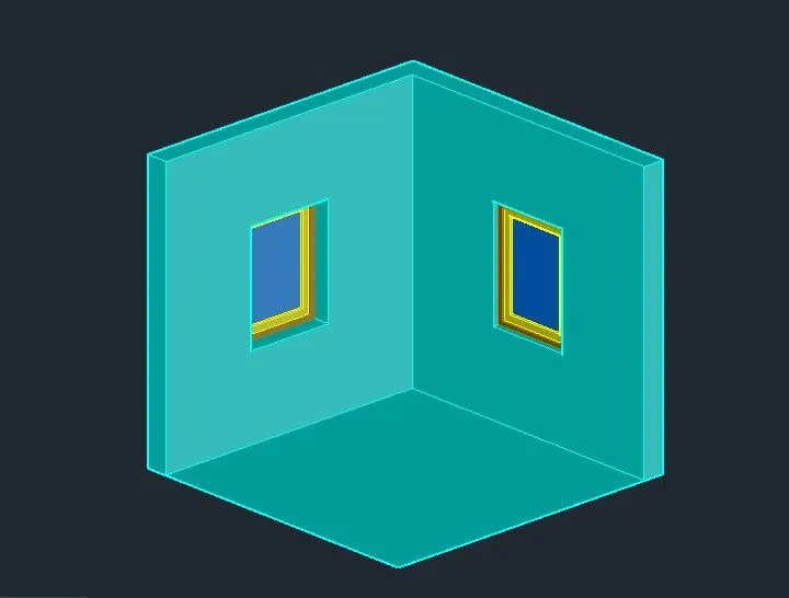
Result :-
- Different views of the drawings are as per in the following images.
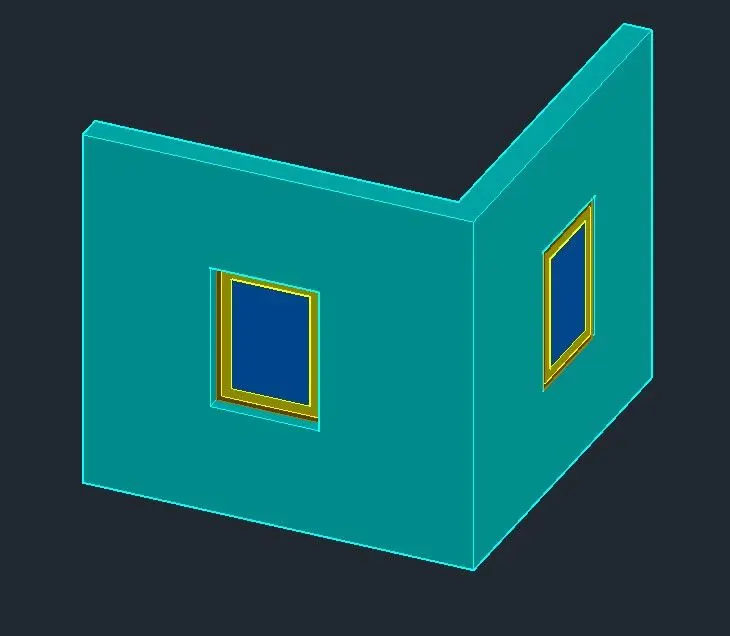
Isometric View 1
Isometric View 2
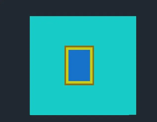
Section - A
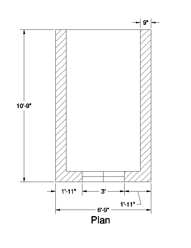
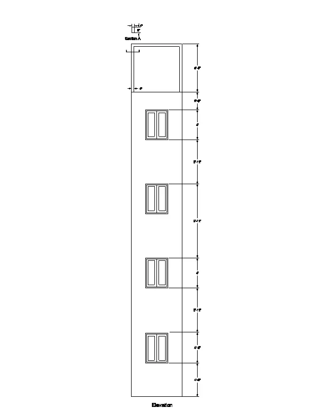
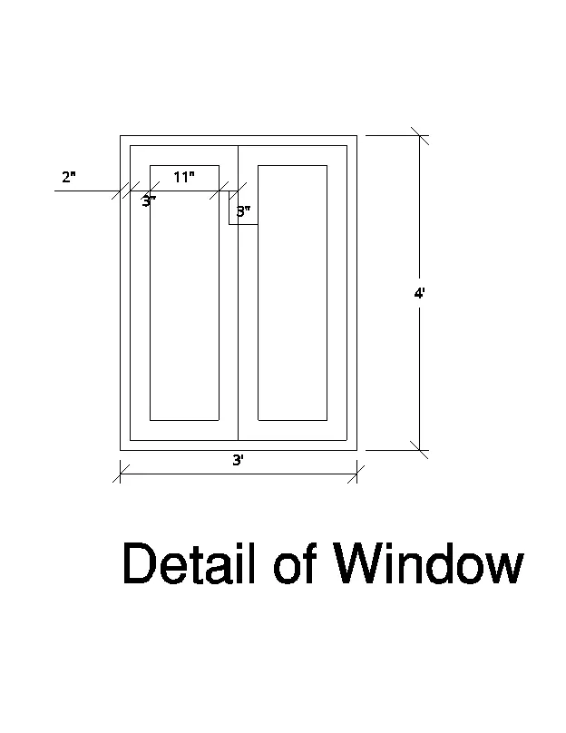
2. Create the 3D View of the Building Façade as given in the plan and elevation. Also, see the detail of the window.
Aim :-
-
To Create the 3D View of the Building Façade as given in plan and elevation with detail of the window.
Introduction :-
- There is the building facade in the drawing which has 4 floors and wall box at the top.
- Which has 3 sided wall.
- There is window in the elevation side wall.
- We are creating the 3D drawing of the Building Facade.
Procedure :-
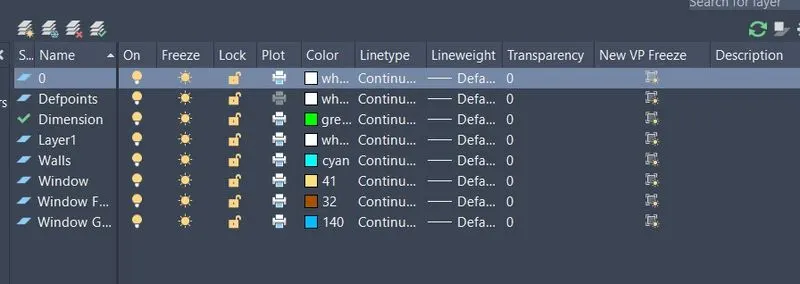
- Open Layer properties and create the different layers for the different components.
- Draw the rectangle of size 6'9" X 10'9".
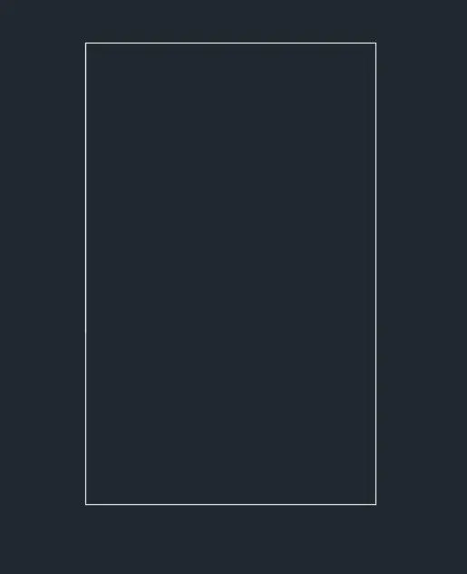
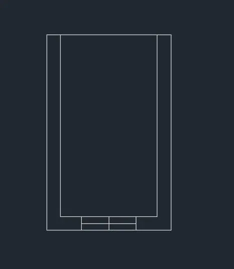
- Now offset the Rectangle with 9" for wall.
- Trim the line from 1 side adn join that line with outer recatangle.
- Draw the line fom the middle of the waal.
- Offset the line with 1'6" both side and make window space.
- Now fill the HATCH in the wall.
- Add the layers to every component.
- Annotate with dimensions.
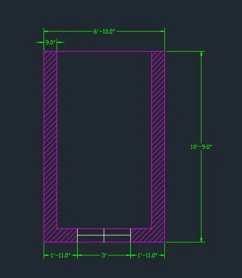
- Select the boundary command and select the boundary of the wall.
- Now select EXTRUDE command and Extrude the walls in upper side with the height of 10'.

- Select the boundary command and select the boundary of the window.
- Now select EXTRUDE command and Extrude the window in upper side with the height of 4'6".
- Now draw the rectangle at the top side of the wall.
- Select the boundary command and select the boundary of the window.
- Now select EXTRUDE command and Extrude the window in upper side with the height of -1'3".
- Select the Union command and select all the wall and press Enter.

- Switch off the layer of walls.
- Draw rectangle of 3' X 4'3".
- offset the rec. 2" and 3" distance inside.
- Now select the Outer rectangle and type boundary command and pick the point.
- It will select whole window.
- Now substract the window frame.
- Do the same process for Window mullion and window glass.
- And add the layers in the Window.
- Extrude the winwow as per the width of wall.
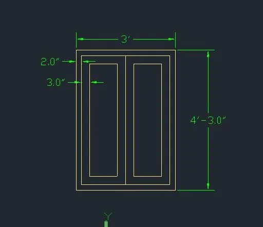
- Now add the layers of window frame, Mullion and Glass.
- Extrude the winwow as per the width of wall.
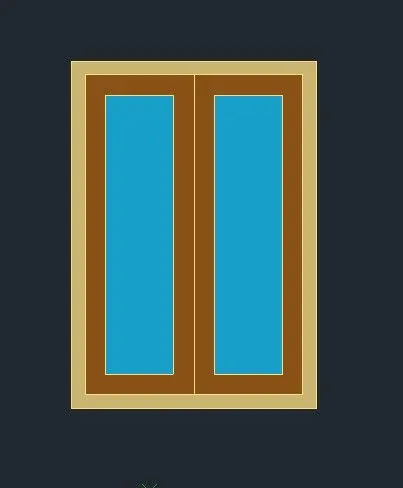
- Now Swith on the layer of wall.
- So the 1 floor of Building Facade is ready.
- Now group the whole drawing and copy the floor 3 times one by one.
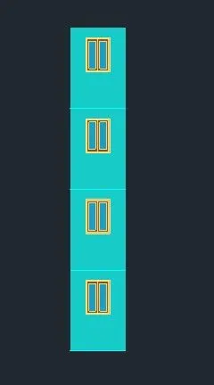
- NOw for top part, draw rthe line of 6'5' upper side and make 1 box.
- Offset the line inside with the size of 4".
- Trime unwanted lines.
- Select the boundary command and select the boundary of the wall.
- Now select EXTRUDE command and Extrude the wall in upper side with the height of 9".
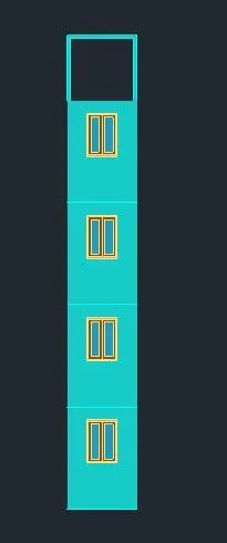
Result :-
- Different views of the drawings are as per in the following images.
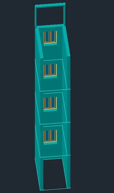
Back- Right View
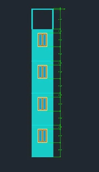
Front View

Top View
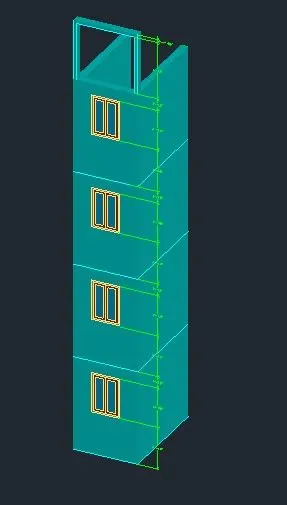
Front - Right View
3. Create the ismoteric 3d view of a stair with railing as shown in the plan and elevation. Assume the size of the balustrades and the hand rails.
Aim :-
- To Create the ismoteric 3d view of a stair with railing.
Introduction :-
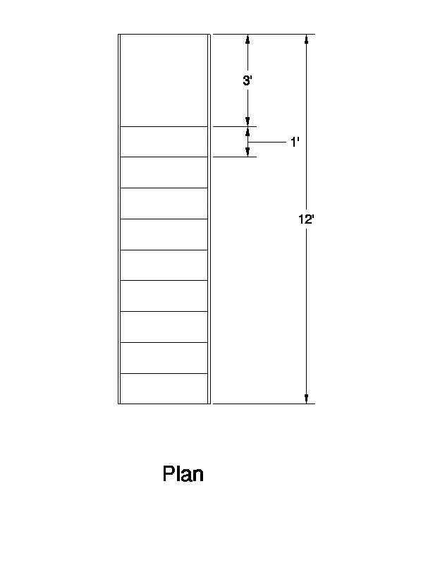
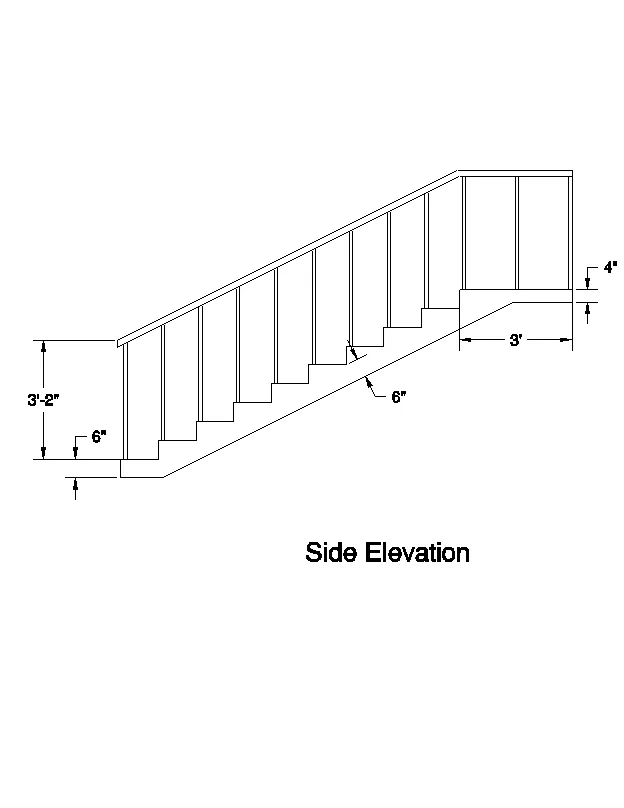
- Plan and Elevation view of stairs is given.
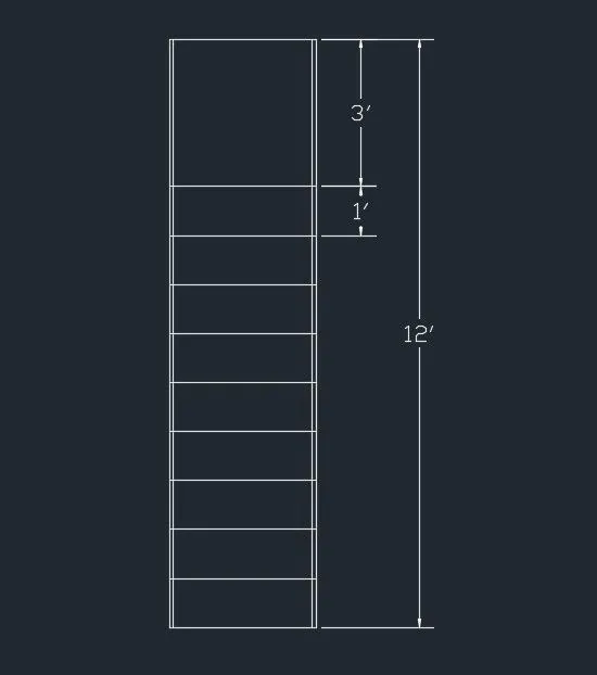
- Length of the stairs with landing is 12' and width is 3'.
- There is 9 tread and 8 risers.
- Length of tread is 1'.
- We are creating the 3D view of a stair with railing.
Procedure :-
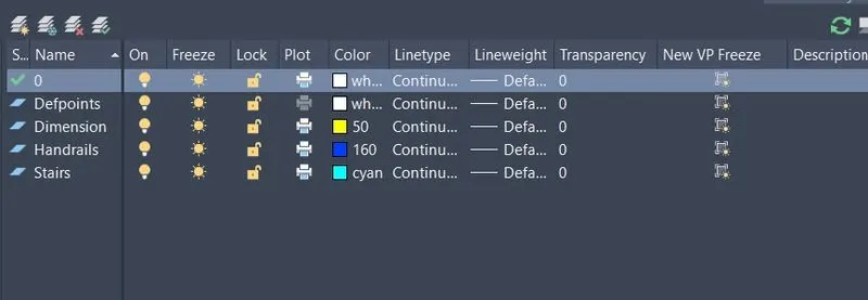
- Open Layer properties and create the different layers for the different components.
- Draw the rectangle of size 3' X 12'.
- From down side offset the3' line with 1' size 9 times.
- Ofsfet the 12' line with 0.5" line.
- Annotate with dimension.
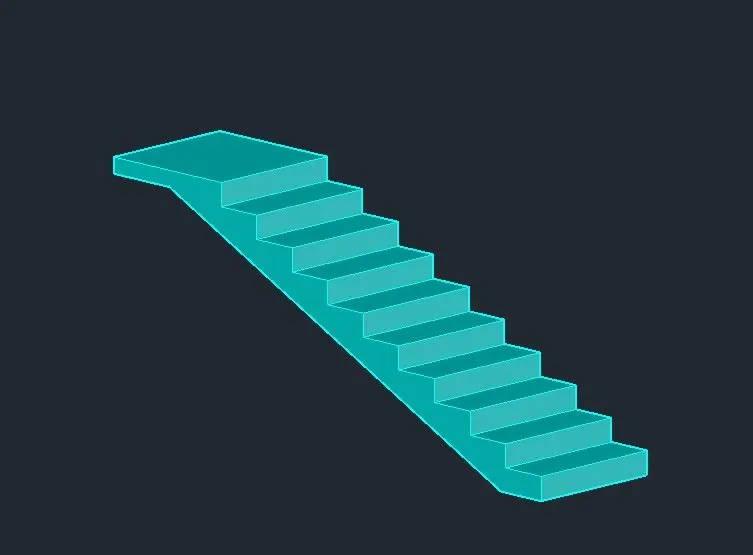
- Now select the line command and draw the line with 6" upper side then 1' right side.
- Repeat the process 9 times.
- Then draw the line of 3' right side in last.
- Draw the slab of 4".
- And connect the downwars side of stairs.

- Select the boundary command and select the boundary of the Stair.
- Now select EXTRUDE command and Extrude the stair in left side with the height of 3'.
- Now draw the circle of 1" diameter at the end of the stair for railing.
- Change the circle into boundary.
- Now select EXTRUDE command and Extrude the circle in upper side with the height of 3'.
- Copy the raili at every stair.
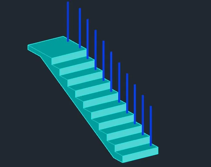
- Now 3DMIRROR all the rails at other side of stair.
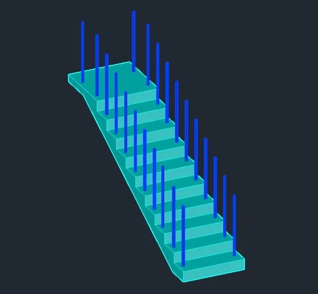
- Now with SWEEP command draw the top hand rail.
- Sweep the cirle in the HAndrail.
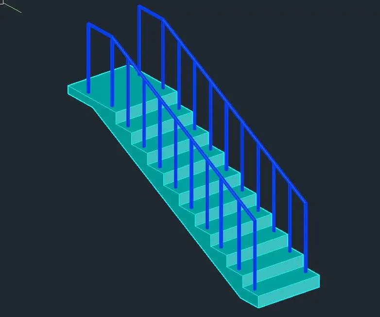
Result :-
- Different views of the drawings are as per in the following images.
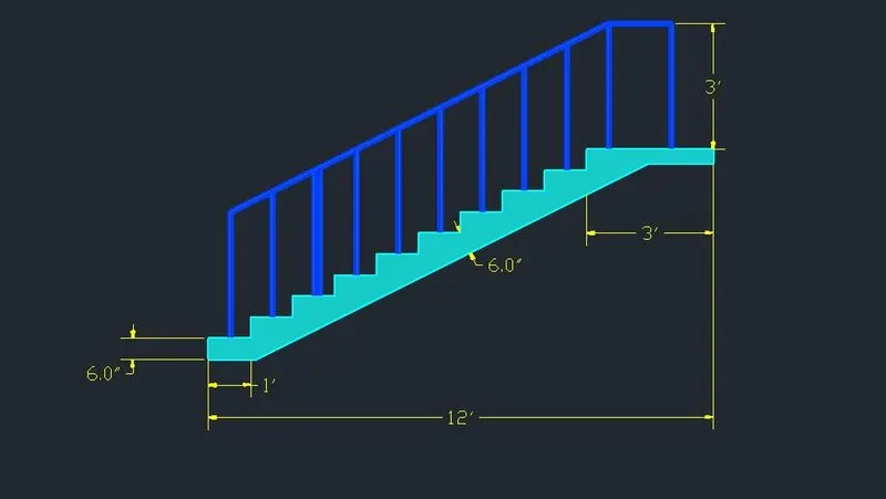
Side Elevation
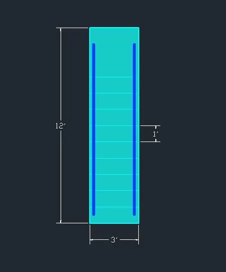
Top View
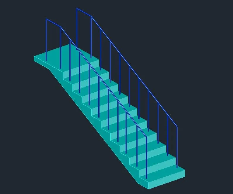
Left-Front View
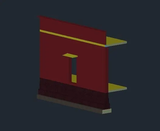
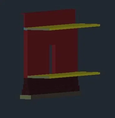
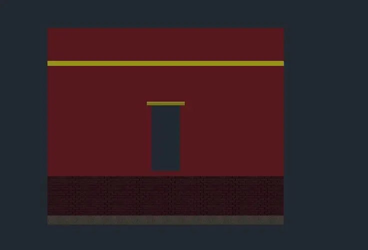
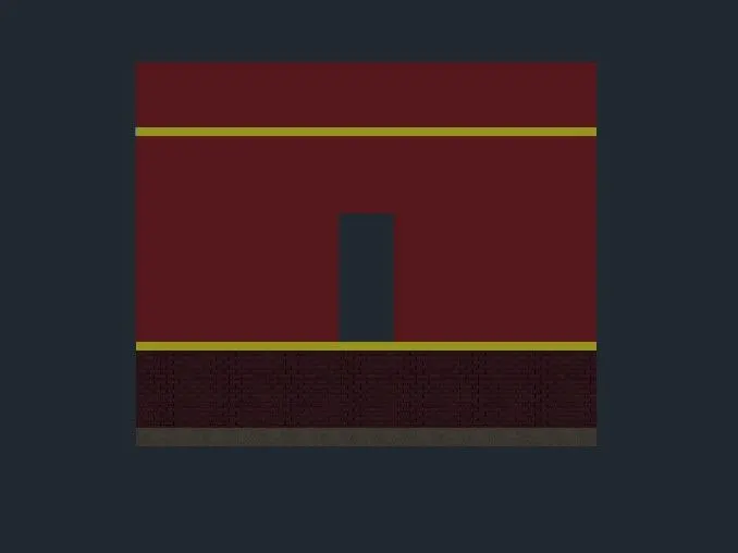
4. Create the 3D view of a Wall with spread footing . Create the Door opening only. Assume the size of the parpaet and the coping. See the plans and elevation for the details. Also, create a rendered view of the model with materials as of your choice.
Aim :-
- To Create the 3D view of a Wall with spread footing and door opening.
Inroduction:-
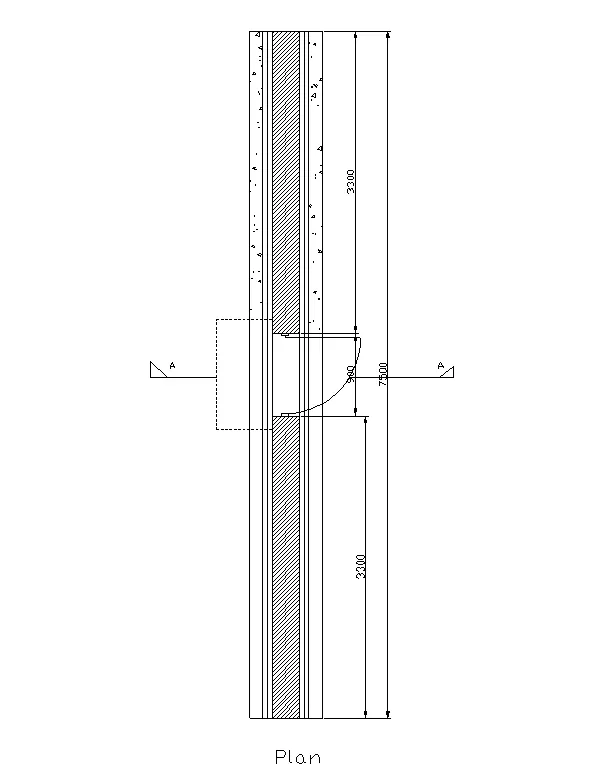
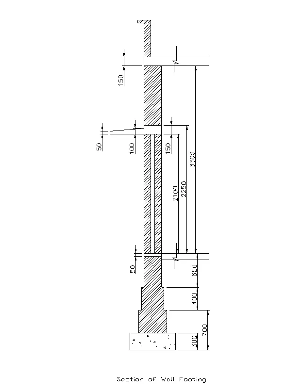
- Plan view and section view of wall with spread footing under it are given.
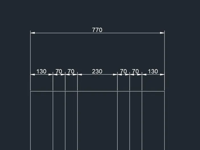
- Plan view consists of horizontal dimesions of footing.
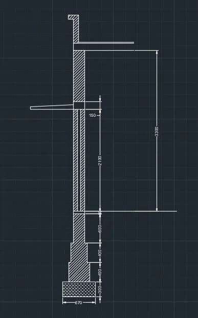
- Elevation view consists of vertical dimensions of different levels of footing.
- Thickness of wall-230 mm
Procedure :-
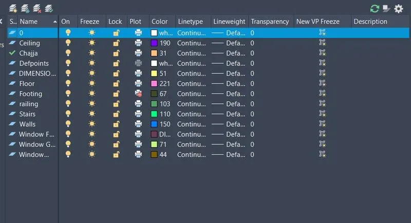
- Open Layer properties and create the different layers for the different components.
- D
- Draw the door opening of 900mm.
- Draw the rectangle of 50 X 100.
- Draw line of 850mm.
- Use Circle command and trim the unwanted line.
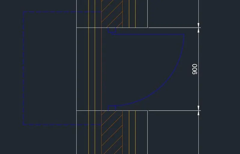
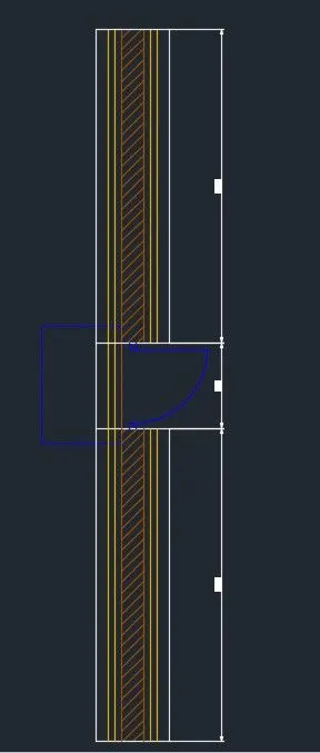
- Place the door 3300 mm away from the corner of the wall.
- Select the layers Respectively.
Elevation View :-
Procedure :-
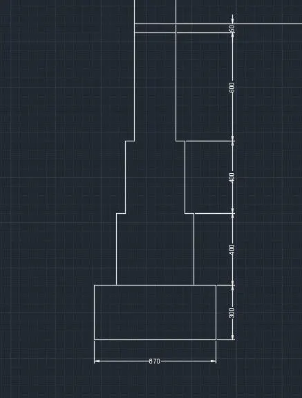
- Draw the rectangle of size 230 X 3300.
- Draw the roof with the thickness of 150 mm.
- Draw the oarapet waal of size of 600 mm.
- Draw the rectangle of size of 230 X 600 below ground level.
- Draw the rectangle of size of 330 X 600.
- Draw the rectangle of size of 430 X 600.
- Draw the rectangle of size 670 X 300 mm for footing.
- Draw the chajjas of some size of projection.
- Do the HAtches in the plan view of Section.
- Now Select the respected areas and place the boundary in it.
- And place whole drawing under boundaries.
- Extrude the Whole drawing 7500 mm .
- Draw the line as per the layers.
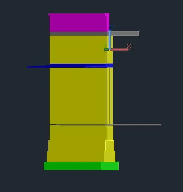
- Plan view of Drawing :-
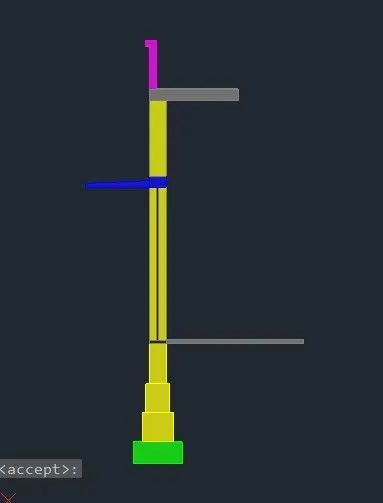
- Rendering is done by adding materials 3D view.
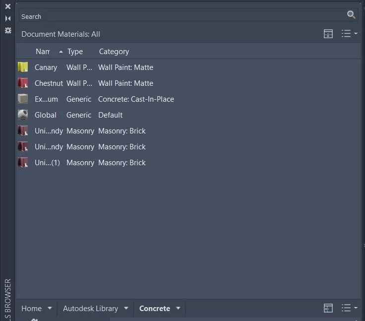
- Material Browser is used to insert the materials in drawing.
- MAterial libraries is as per following.
Result :-
- Results of rendered drawing is as per following.
Right-Front View
Left- Bottom View
Front Elevation View
Side Elevation