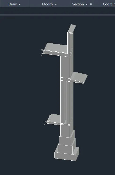
Creating 3D Isometric view of various structural elements in AutoCAD
Ans 1)
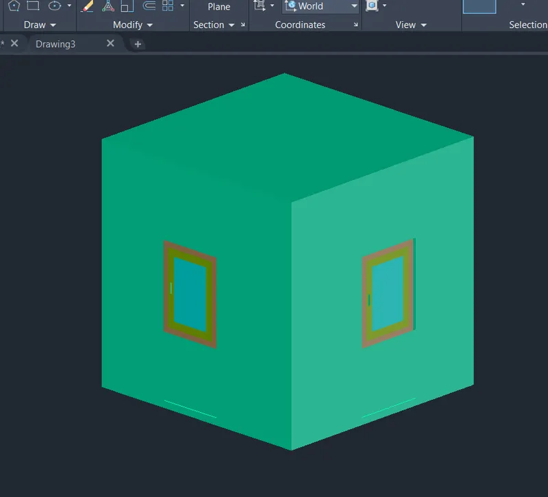
Aim: Create a 3D Isometric View of the building with plan and elevation in AutoCAD by using proper dimensions.
Procedure:
Select "rectangle" tool from the draw panel or type rec in command prompt and press enter.
Specify the first point and press enter.
Give the dimensions as 10'9 by 10'9 and press enter.
Draw the plan in 2D view.
Draw walls and windows and press enter.
Now Extrude the rectangle by 10' and press enter.
Again extrude the window part by 3' and press enter.
Now Shift the UCS and press enter again draw the rectangle and press enter.
Extrude the rectangle in negative direction by 3' and press enter.
Draw the Window separately as per the dimensions and press enter.
Group all the elements of window and press enter.
Move the window to the location of the window.
Use render command or type RR in command prompt and press enter.
Press esc to finish.
Ans 2)
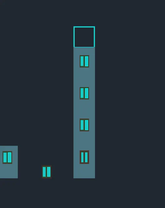
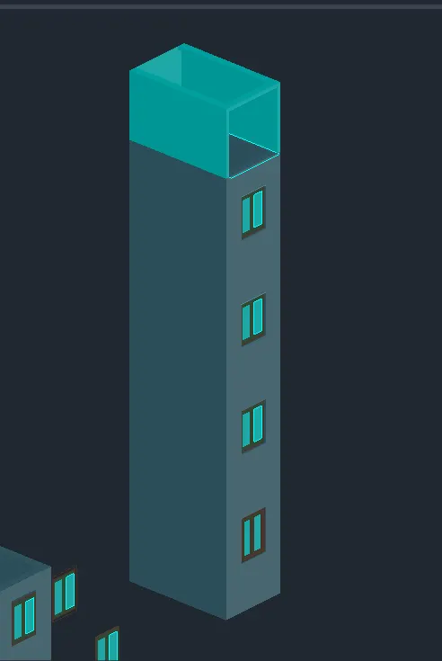
Aim: Create the 3D View of the Building Façade as given in the plan and elevation in AutoCAD by using proper dimensions.
Procedure:
Select "rectangle" tool from the draw panel or type rec in command prompt and press enter.
Specify the first point and press enter.
Give the dimensions as 6'9 by 10'9 and press enter.
Draw the plan in 2D view.
Draw walls and windows and press enter.
Now Extrude the rectangle and press enter.
Again extrude the window part by 4'6 and press enter.
Now Shift the UCS and press enter again draw the rectangle and press enter.
Now make the offset of 4'2 and press enter.
Again extrude the rectangle and press enter again shift the ucs above it and draw rectangle anf follow the same steps as above and press enter.
Draw the Window separately as per the dimensions and press enter.
Group all the elements of window and press enter.
Move the window to the location of the window.
Use render command or type RR in command prompt and press enter.
Press esc to finish.
Ans 2)
Aim: Create the 3D View of the Building Façade as given in the plan and elevation in AutoCAD by using proper dimensions.
Procedure:
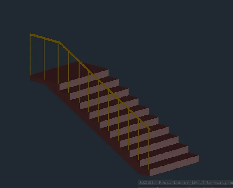
Select "line" tool from the draw panel or type line in command prompt and press enter.
Specify the first point and press enter.
Give the dimensions as 6" in vertical direction and in horizontal direction as 1' press enter.
Draw the plan in 2D view.
Now Extrude the plan and press enter.
Draw the railing of the starts and press enter.
Use render command or type RR in command prompt and press enter.
Press esc to finish.
Ans 2)
Aim: Create the 3D View of the Building Façade as given in the plan and elevation in AutoCAD by using proper dimensions.
Procedure:
Select "rectangle" tool from the draw panel or type rec in command prompt and press enter.
Specify the first point and press enter.
Give the dimensions and press enter.
Draw the plan in 2D view.
Now Extrude the plan and press enter.
Use render command or type RR in command prompt and press enter.
Press esc to finish.