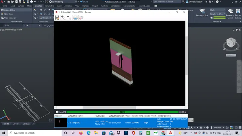
Creating 3D Isometric view of various structural elements in AutoCAD
Aim: - to create 3d isometric views of the building as shown in the figure.
Procedure: -
- Units- engineering.
- Go in 3d modelling workspace.
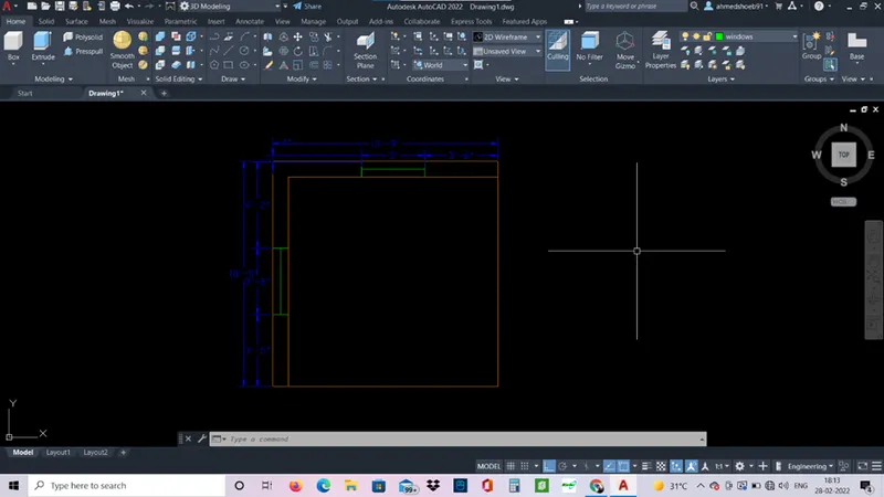
- In the top view. Draft the 2d drawing of the model.
- Use line. Offset and trim command.
- Give the dimensions using dimlinear.
- Go in isometric view.
- Give region to the walls using boundary command.
- Extrude the walls 10’
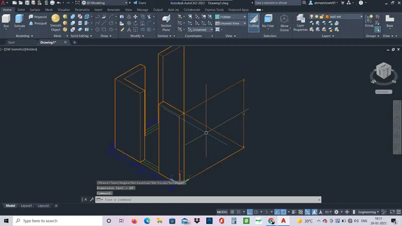
- Again make a rectangle in the windows area and extrude it to required height.
- Make a rectangle on top of the window area and extrude downwards.
- Use the union command and join the walls.
- Use ucs command and face command and give dimensions.
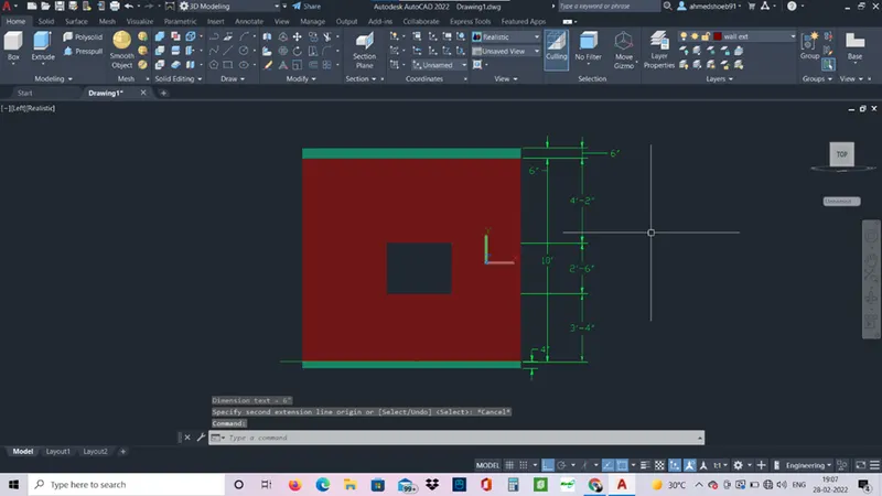
- Windows are made outside can be placed in window openings.
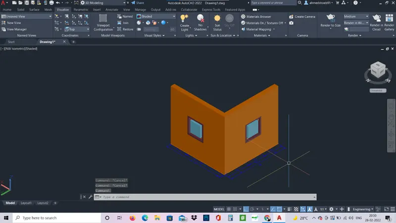
Result: -
An isometric view of the building is created in AutoCAD.
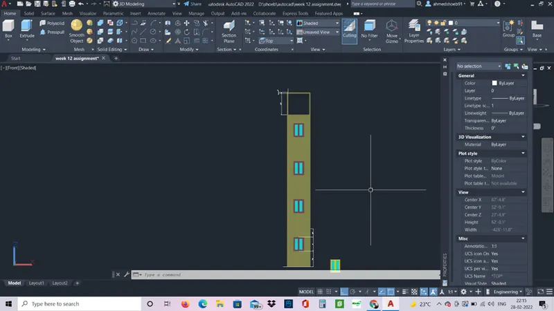
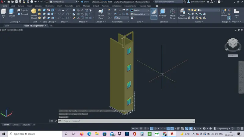
Aim: - To Create the 3D View of the Building Façade as given in the plan and elevation. Also, see the detail of the window.
Procedure: -
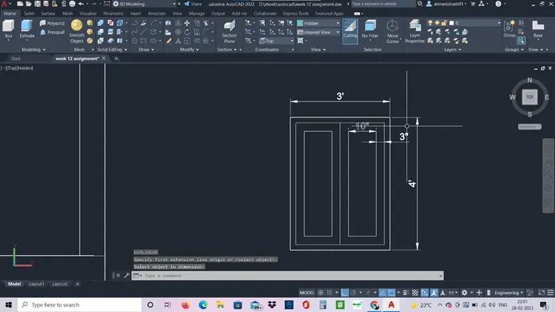
- In 3d modelling workspace go to top view and make a 2d draft of the buildings.
- Use line, offset and trim command make a plan, also give dimensions.
- Give the region to the walls and extrude it to 10’.
- For window go to ucs and face select the front of the wall make a rectangle of 4’x 3’ give it region and extrude in z direction.
- Use subtract command and subtract the window section.
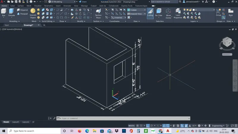
- Select the whole drawing and make a copy of it paste it in floor direction.
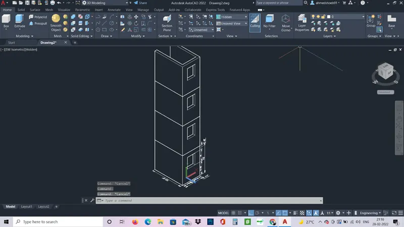
- Use the union command and make a union of all the walls .
- Go to top view and make the terrace drawing and extrude it 9”.
- Since this drawing in xy plane use 3dorbit command and select the z axis and rotate it 90 degrees move it to the top floor.
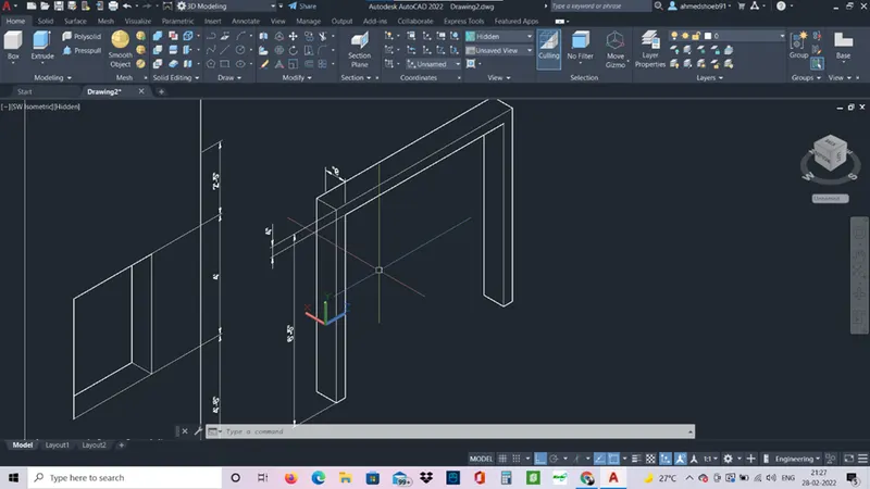
- Make windows as given and copy paste it in the openings.
Result: -
The 3d model of the building is created in Autocad.
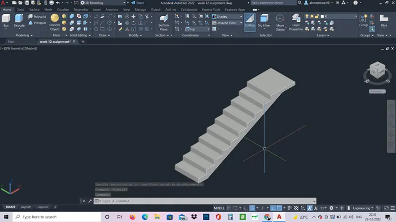
Aim: - To Create the ismoteric 3d view of a stair with railing as shown in the plan and elevation.
Procedure: -
- Set ucs at right.
- Use line command and make 2d drawing of the building with thread as 1’ and riser as 6”.
- Make the landing 3 feet.
- Give the waist slab as 6”.
- Join the whole drawing using join command.
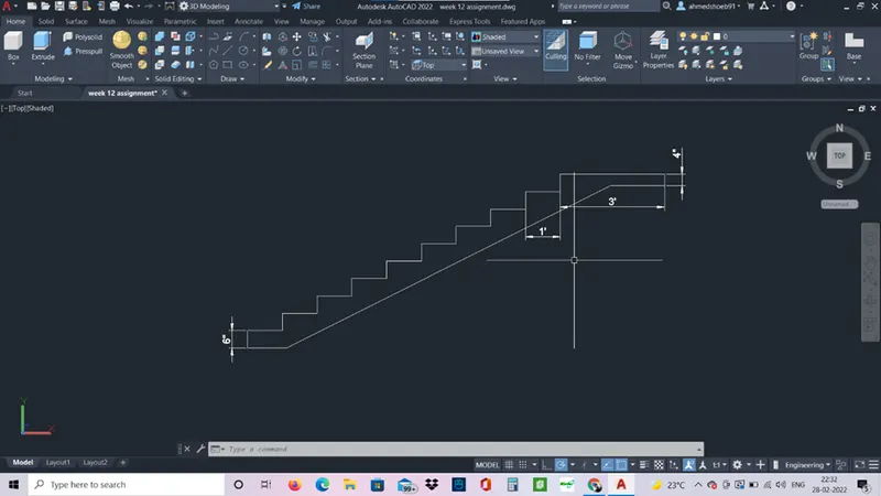
- Give the boundary to the stairs to make region.
- Go in isometric view and extrude the whole drawing 3’.
- Set ucs on bottom of the stair and make circle of 1 inch dia. Extrude it 3’.
- Copy paste the single railing on all on all threads.
- Use 3dpolyline command and make a polyline on top of the railings connecting it.
- Make a circle of 1” dia.
- Use sweep command and sweep the this 1” circle in to that polyline.
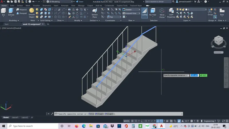
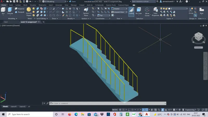
- Make a copy of the railing on the other side.
Result: -
Aim: - Create the 3D view of a Wall with spread footing and the Door opening only. Assuming the size of the parpaet and the coping. Also, to create a rendered view of the model with materials.
Procedure: -
- Units – decimal.
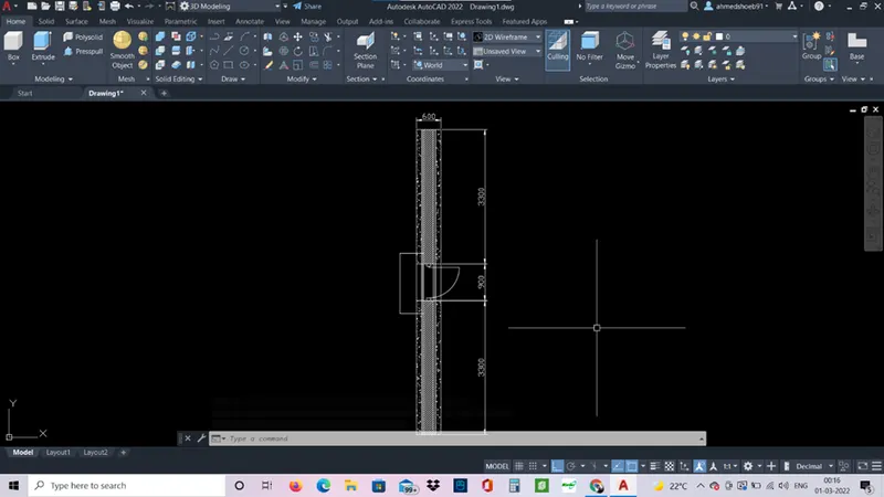
- Go to top view and draw a vertical line of 7500mm and horizontal line of 600mm.
- Give the line in center and make offsets.
- Divide the 600mm line in 230mm 300mm and 350mm.
- Divide the vertical line 3300 from top to 900mm and 3300 from bottom for door.
- Provide hatch on the outer and inner region .
- Provide outer for conc and inner for slanted lines.
- Create a section of wall footing.
- Create a vertical line of 4550 mm.
- Give vertical offsets of 300,400,400,600,2100,150,1050 and 150mm. in vertical direction
- Trim the excess lines and make a section.
- Give region to the rectangles using boundary command.
- Extrude the whole drawing 5000mm.
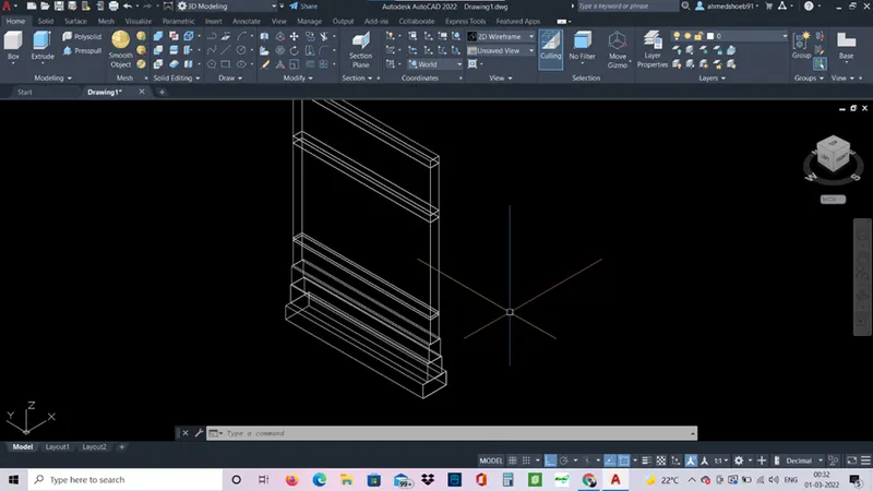
- Place the ucs on the left face of the section.
- Make a rectangular profile in the section for the door.
- Extrude the rectangle and subtract it.
- Use 3dpolyline command and make a chajja on top of the door
- Extrude it for 50mm to 150mm.
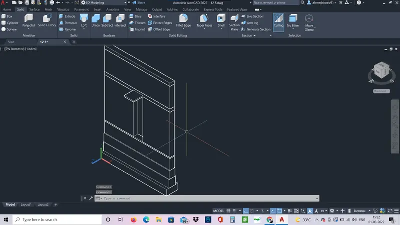
- Go in visualize ribbon and select materials.
- Assign material to the regions.
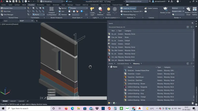
- Create a camera and make a view facing the wall.
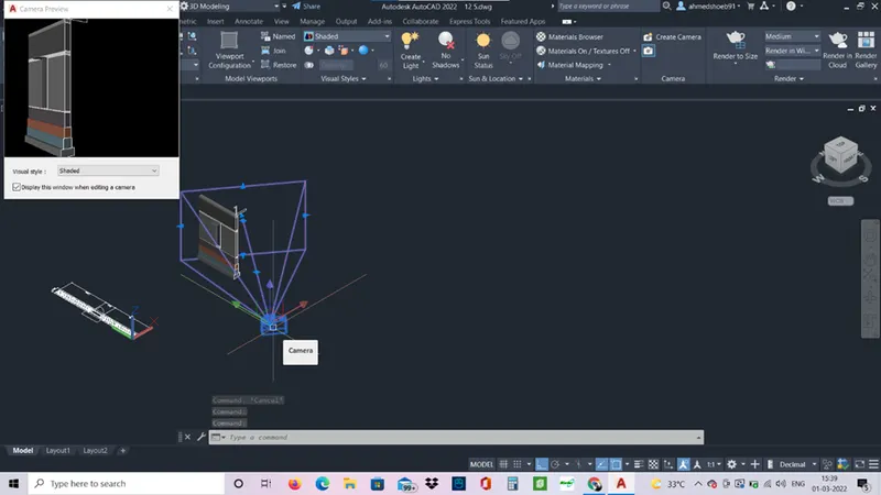
- Go in render command and render the drawing using viewport.
- You can also use rr command for rendering.
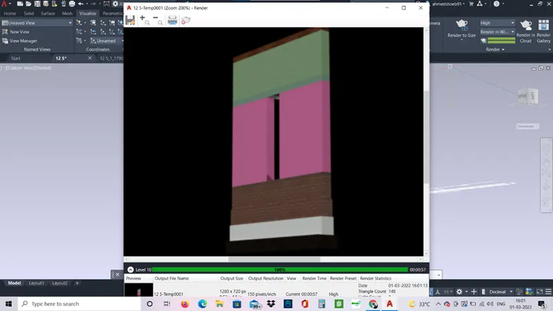
Result: -
The rendered view of the wall section is created in the Autocad.