AutoCAD_Residence Floor Plan, Seating Plan, Toilet and Utility room Plan_Week 4
AIM :
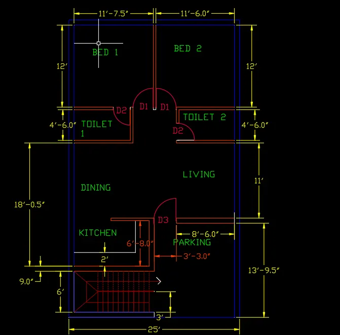
sketch the layout of residence as shown in figure. consider all dimensions as reference to sketch the unit plan. also the text in the layout are only for reference. assume the missing dimensions. also refer the schedule for the size of doors.
PROCEDURE :
open the autocad, first thing to do is press UN enter to invoke the unit command.
change the settings to engineering and precision as per you want, set the units to inches.
then invoke the maximum limit on the sheet by pressing limmax command, set it as 100',100'.
then press limmin enter to invoke the command minimum limits ,set it as 0',0'.
then press z enter a enter (where z = zoom, a = all).
press xl enter on the keyboard and select the horizontal or vertical line option one after the other.
let us start by horizontal and draw the line, then take the offset of 9 inches ,which marks the exterior wall
of the plan , similarly take the same offset on the vertical side, press tr enter to trim the unnecesary lines.
take the offset of 6' followed by an offset of 9inches in the horizontal direction.
take the offset of 12'6 from the left vertical direction and an offset of 9 to the same wall.
take an offset of 6'4 from the previous wall ,and take an offset of 4.5 to the same wall above it.
take an offset of 11'in the above the previous line followed by an offset of 4.5.
take an offset of 8'3 in the left vertical direction from the exterior left vertical wall,
and an offset of 4'6 in the horizontal above the dining wall.
then take an offset of 4.5 above this wall ,then from this wall take an offset of 12' in the horizontal and
11'7.5 in the vertical followed by an offset of 4.5 to mark the internal boundary of bed1, then take an offset of 9 on this wall to mark the external boundary.
take an offset of 11'6 from this internal wall ,followed by an offset of 9 to mark its external boundary.
take an offset of 12' from the top external boundary of bedroom 2 ,followed by an offset of 4.5
then take an offset of 8'1.5 from the right external boundary and an offset of 4.5 to it.
mark the staircase by taking an offset of 6 starting from the first line upto specified number of stairs.
mark all the internal and external dimensions as per shown in the plan.
door size is given , therfore as per the size take the required offsets at the boundary of every room,
and trim the unnecessary lines, after drawing the required width of door, and taking an offset , then in order to show the inward or outward movement of door, a circle is drawn keeping the centre of circle at door hinge and then drawing it upto the entire width of door, then trim the remaining portion until it forms an arc.
go to the layer properties at the top, and select the new layer and start naming one after the other such as stair, door ,interior wall, exterior wall, dimensions, text, and all the components of plan,
assign colour to all these components as per your requirement, select each component of plan and assign colour as per the layers , by entering la command.
AIM : Sketch the seating plan for an outdoor canopy. assume the dimensions for seating. also consider the dimensions in mm.
PROCEDURE :
open the autocad, first thing to do is press UN enter to invoke the unit command.
change the settings to engineering and precision as per you want, set the units to mm.
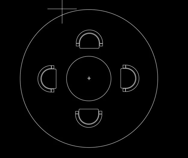
invoke the circle command by pressing c enter command and enter the radius which 1398 units.
keeping the same centre draw another circle of radius 452.
to draw the seats ,since there is no dimension given so draw accordingly.
draw a rectangle of assumed dimension, then use the arc command and select the option
start ,end ,direction and draw a semicircle ,take an offset of 100 units to this arc, join the intermediate line.
draw two small rectangles on either sides, select this entire seat and rotate it in the required direction
and place as per given in the figure.
mark the dimensions of both the circles .
AIM :
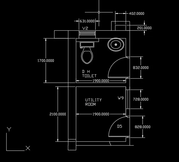
Sketch the part plan for toilets and utilities room. consider the outer wall thicknessa as 300mm and inner wall as 150mm. also assume the missing dimensions ,texts and hatches are only for reference. also symbols for toilets and w/c rooms are only for reference.
PROCEDURE :
open the autocad, first thing to do is press UN enter to invoke the unit command.
change the settings to engineering and precision as per you want, set the units to mm.
then invoke the maximum limit on the sheet by pressing limmax command, set it as 100',100'.
then press limmin enter to invoke the command minimum limits ,set it as 0',0'.
then press z enter a enter (where z = zoom, a = all).
press xl enter on the keyboard and select the horizontal or vertical line option one after the other.
take an offset of 300mm to the vertical line, followed by an offset of 150mm to the horizontal line,
take an offset of 2100 to the horizontal line and an offset of 1900 to the vertical wall,
again take an offset of 150mm to both the offseted walls,
take an offset of 1700 to the horizontal wall above the utility room, and an offset of 1900 to the vertical wall, followed by an offset of 150mm
to the previous wall, now come to doors and windows.
for the utility room door, just draw a horizontal line and take an offset of 828 to this line.
after drawing the required width of door, and taking an offset , then in order to show the inward or outward movement of door, a circle is drawn keeping the centre of circle at door hinge and then drawing it upto the entire width of door, then trim the remaining portion until it forms an arc.
to draw the window just draw a horizontal line as shown in plan and take an offset of 728, and draw a vertical line in the middle.
to draw the door of toilet just draw a horizontal line and take an offset of 832 to this line.
after drawing the required width of door, and taking an offset , then in order to show the inward or outward movement of door, a circle is drawn keeping the centre of circle at door hinge and then drawing it upto the entire width of door, then trim the remaining portion until it forms an arc.
to draw the ventilator, just draw a vertical line at the position shown in figure, and take an offset of 631, and show some lines in the middle.
to show the componets such as wash basin, toilet, press the command, d enter c enter,
then select housing materials where all these materials will be shown ,just drag it from there and bring on to the required place
in the plan.mark the internal and external dimensions and complete the figure.