Conceptual design of a building with columns and shear walls
CONCEPTUAL DESIGN OF A BUILDING WITH COLUMNS AND SHEAR WALLS
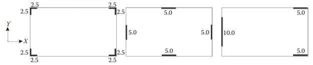
TASK 1: The building shown, 20 × 35 m in the plan, has columns on a 5 × 5 m grid and shear walls (with dimensions shown in m, 250 mm in thickness) in three alternative arrangements, (a), (b), (c), all with the same total cross-sectional area of the shear walls. Compare the three alternatives, taking into account the restraint of floor shrinkage, the lateral stiffness and the torsional one with respect to the vertical axis, the vertical reinforcement required for the same total flexural capacity at the base, the static eccentricity, the system’s redundancy, foundation systems, architectural constraints, etc.
Solution:
CASE 1 CASE 2 CASE 3
Restraint of floor shrinkage:
Case 1: In this case, the shear walls are placed at the corners and it has good restraint against floor shrinkage. These shear walls at the corners will tightly hold the floor in position and the shrinkage will be in control.
Case 2: Here, the shear walls are placed along the edges of the wall on all four sides. This wall will provide better stability to the floor near it but the corner portions of the floor are subjected to shrinkage, where there are no shear walls.
Case 3: Here, since the shear walls are not placed symmetrically. Both the long edges and right short edges of the wall are prone to shrinkage as there is no shear wall at the right side and along the long edges the shear wall is placed only at the rightmost edge.
Lateral stiffness:
Case 1: As the shear walls are placed at the corners of the floor, the edges of the floor don't have any support and since the earthquake force or the seismic force tends to act along the edges of the floor, this placement of shear walls will have the least stability and hence the lateral stiffness will also be less.
Case 2: Here as the shear walls are placed along the edges which is the same direction of earthquake excitation, the structure will have more stability and as such the lateral stiffness will also be more along both the principal planes.
Case 3: Here along the X direction there are two shear walls that enhance the stiffness in that direction, whereas in the Y direction, there is only one shear wall at the left which leads to the concentration of seismic force in that wall and causes instability and reduces the lateral stiffness in that direction.
Torsional stiffness with respect to vertical axis:
Case 1: Here the placement of shear walls is symmetric, hence there is no eccentricity between the centre of mass and centre of stiffness, both coincides, so it is less prone to Torsion and can be regarded as a torsionally stiff model.
Case 2: In this arrangement also, the placement of shear walls is symmetric and there is no eccentricity between the centre of mass and the centre of stiffness. Hence, this arrangement is also less prone to torsion.
Case 3: In this arrangement, the shear wall placement is unsymmetrical along the Y direction. So, the centre of stiffness shifts towards the left edge and as such, there is eccentricity between the centre of mass and centre of stiffness which leads to torsional instability in this arrangement.
The vertical reinforcement required at the base:
Case 1: As the shear Reinforcements are placed at the corners, it doesn't take part much in the resistance of the lateral forces as compared to the other parts of the wall. As such the amount of reinforcement required for these walls will be less.
Case 2: Here, a huge amount of the lateral forces are taken by these shear walls as they are placed along with the principal directions themselves. Hence these walls should be provided with much more reinforcement to resist these forces.
Case 3: In the third arrangement, as the shear walls are asymmetrically placed, a large number of lateral forces will be taken by the shear walls, especially the wall at the left edge. Hence these walls need to be heavily reinforced.
The static eccentricity:
Case 1: In this arrangement, as the shear walls are symmetrically placed at the corners, the centre of mass and centre of stiffness coincide and there is no eccentricity.
Case 2: In this arrangement, as the shear walls are symmetrically placed along the edges, the centre of mass and centre of stiffness coincide and there is no eccentricity.
Case 3: Here, the shear walls are symmetrically placed along with one of the principal directions (X direction), but in the Y direction there is only one shear wall along the left edge with a heavier mass compared to the other two shear walls. Due to this, the centre of stiffness shifts to the left side and hence there is eccentricity in the arrangement.
The systems redundancy:
Case 1: This arrangement has shear walls at its corner and as such it doesn't actively take part in resisting the lateral force. So a huge amount of the lateral force has to be taken care of by the other part of the structure. Hence, the structure is less redundant.
Case 2: Here, due to the symmetric arrangement of shear walls along the mid half of each edge, the forces are equally shared among them. Hence, this arrangement has really good redundancy.
Case 3: As this arrangement of shear walls is asymmetric and also there is the concentration of load at the left edge, this arrangement is not redundant. It has poor redundancy.
Foundation systems:
Case 1: As the shear walls are placed at the corners of the structure, an isolated footing with a tie beam can be provided as a foundation.
Case 2: In this arrangement, since the shear walls are spread across the 4 edges of the structure, a raft foundation or box type foundation can be provided.
Case 3: In this arrangement, two shear walls are provided along X direction so for this, a combined footing can be provided along Y direction connecting these two shear walls. The other shear walls at the left edge can be provided with an isolated footing.
Architectural constraints:
Case 1: This arrangement of shear walls is appealing from an architectural point of view, as it doesn't interfere with any other elements like doors, windows etc.
Case 2: This arrangement is a stable arrangement, but from an architectural point of view there is a chance that these shear walls may be hindered by the wall openings which is not suitable.
Case 3: In this arrangement, the two walls at the right side along X direction are architecturally fine but the shear wall at left edge along Y direction occupies almost half of the wall, which can cause hindrance to the open spaces.
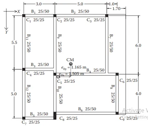
TASK 2: Discuss the suitability for earthquake resistance of the moment-resisting framing plan of a three-story building depicted here (cross-sectional dimensions in cm), the eccentricity of the centre of mass (as the centroid of floor plan) to the centre of stiffness (from the moments of inertia of the columns) are shown. Suggest an alternative. Also, is there torsional flexibility? Are the two fundamental translational modes of vibration larger than the fundamental torsional mode of vibration. Discuss qualitatively.
Solution:
In this structure, there is complexity in load transfer at three locations due to the absence of a vertical member near the horizontal member.
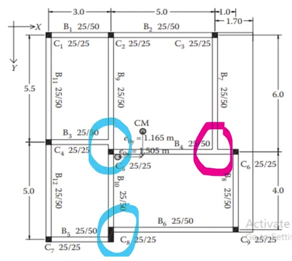
- Incomplete Lateral load transfer in X-Direction indicates in blue colour & Lateral load transfer in Y-Direction indicates in Pink colour.
- Some rearrangement in the plan can be done to create an effective load transfer mechanism.
Alternative plan:
The complex load transfer process is eliminated and a regular structure has been created.
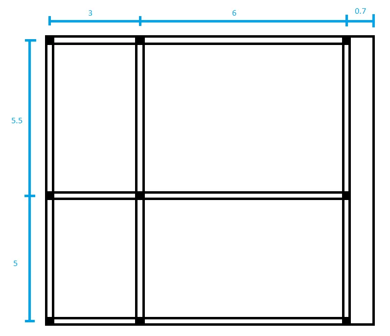
- In this alternative arrangement, each of the horizontal members is provided with two vertical members at its ends for the effective transfer of loads. Hence, the complexity is removed.
- Here, since there is eccentricity between the centre of mass and the centre of stiffness, torsional flexibility does exist. Hence, the building will rotate about the vertical axis. Still, the plan aspect ratio is less than 3(within the IS1893 limit), by which we may assume the given structure is well proportioned.
- Also, the given structural floor system is not effective in transferring lateral loads to vertical elements due to too many offsets and beam to beam connections. The response of building in the fundamental mode of translations is the worst.
- The two fundamental modes of the translation may be still higher than the fundamental mode of translation.
TASK 3: A multi-story building with a basement, with a quadrilateral (non-symmetrical floor plan) plan, has interior columns in an irregular (not in a grid) pattern in a plan that serves architectural and functional considerations. Partition walls and interior beams supporting the slab have a different layout in different stories. However, there is no constraint to the type, location, and size of the lateral force-resisting components and sub-systems on the perimeter. Proposals are to be made and justified for the choice of the lateral-load-resisting system and its foundation.
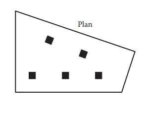
Three main lateral load resisting systems in a building include:
- Shear wall or RC wall system
- Moment resisting frame system: Normal frame of beams, columns, rigid or semi-rigid connections. The stiffness and strength are proportional to the height of storey and column spacing.
- Dual systems of frames and walls
Due to the irregular shape of the floor plan, the most suitable type of lateral load resisting system is the shear wall system or RC wall system, which can be provided at the corners.
By providing this shear wall, torsional rigidity can also be maintained for the structure.
The placement of the shear wall is given below:
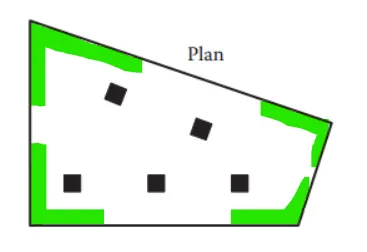
For this arrangement, the type of foundation to be provided can be a box type Foundation that can together accommodate all the shear walls as well as all the columns.