Conceptual design of a building with columns and shear walls
1)
Restraint of Floor Shrinkage
Observations
- From the first plan,we can find that the shear walls are provided all around the corners where by the the corners are fully restrained and the shear provided are also symmetrical on both the sides.
- From the second plan,we can find that the shear walls are provided on all the edges,and the provided shear walls are symmetrical in both the directions.Here,the corners are left free.
- From the third plan,the provided shear walls are not symmetrical on the vertical direction but symmetrical in hprizpntal direction thus can be concluded as the not symmetrical shear walls.
Conclusion
- From the first plan,we can conclude that the slab is subjected to the cracking due to the restraints provided at the corners.
- From the second plan,we conclude that it will also be subjected to cracking to but comparatively less than the first plan.
- From the third plan,we can conclude that the provided restraints are non uniform,hence it will result in the less possible cracking of the slab.
So,from the 3 above plans,the first and the second are good when compared to that of the third plan,where the second one is the better and recommended due to the less cracking when compared with the first plan.
Lateral Stiffness
Observations
- From the first plan,we can find that the shear walls are provided all around the corners where by the the corners are fully restrained and the shear provided are also symmetrical on both the sides.
- From the second plan,we can find that the shear walls are provided on all the edges,and the provided shear walls are symmetrical in both the directions.Here,the corners are left free.
- From the third plan,the provided shear walls are not symmetrical on the vertical direction but symmetrical in hprizpntal direction thus can be concluded as the not symmetrical shear walls.
Conclusion
- We can conclude from the first plan that the lateral stiffness provided to the slab is comparatively better than the third plan,as the corners are restrained where when the load acts at the middle some sort of bending will be present in this type of the plan.
- We can conclude from the second plan that,it will have a very better lateral stiffness due to the presence of the shear walls at the edges as shown where it will resist the bending at the middle due to any load in a better way.
- In this case,it will not provided a better lateral stiffness due to the presence of the non uniform shear walls.
Hence,the second plan will provide the higher lateral stiffness in both the directions for a pure seismic accelaration.
Torsion with respect to the Vertical Axis
Observations
- From the first plan,we can find that the shear walls are provided all around the corners where by the the corners are fully restrained and the shear provided are also symmetrical on both the sides.
- From the second plan,we can find that the shear walls are provided on all the edges,and the provided shear walls are symmetrical in both the directions.Here,the corners are left free.
- From the third plan,the provided shear walls are not symmetrical on the vertical direction but symmetrical in hprizpntal direction thus can be concluded as the not symmetrical shear walls.
Conclusion
- From the first plan,we can conclude that the presence of the corner shear walls as shown will provide a very good resistance for the torsion and resists the twist.
- From the second plan,we can conlcude that this plan is some what better and provides the torsional resistance lesser than the first plan.
- This type of the plan provides very less torsional resistance when comparaed with the remaining 2 plans and is the worst in all the cases.
Hence,for this specific case,the first plan is the ulitimate good one.
Vertical Reinforcement for similar Base Capacity
Observations
- From the first plan,we can find that the shear walls are provided all around the corners where by the the corners are fully restrained and the shear provided are also symmetrical on both the sides.
- From the second plan,we can find that the shear walls are provided on all the edges,and the provided shear walls are symmetrical in both the directions.Here,the corners are left free.
- From the third plan,the provided shear walls are not symmetrical on the vertical direction but symmetrical in hprizpntal direction thus can be concluded as the not symmetrical shear walls.
Conclusion
- The first plan is subjected to the heavy twisting moment and nominal flexural moment,so they require the vertical reinforcement for the nominal flexural moment.
- The second plan is subjected to the nominal twisting moment,and here the shear walls are uniform and present along the edge,so they do require comparatively lesser reinforcement to the first plan.
- As,the walls are eccentric in both the direction,they are subjected to heavy flexural moment and twisting moment,hence they do require a lot of the vertical reinforcement comparatively.
Hence,we can conclude that the third plan do require a lot of reinforcement and the second plan requires less vertical reinforcement.
Static Eccentricity
Observations
- From the first plan,we can find that the shear walls are provided all around the corners where by the the corners are fully restrained and the shear provided are also symmetrical on both the sides.
- From the second plan,we can find that the shear walls are provided on all the edges,and the provided shear walls are symmetrical in both the directions.Here,the corners are left free.
- From the third plan,the provided shear walls are not symmetrical on the vertical direction but symmetrical in hprizpntal direction thus can be concluded as the not symmetrical shear walls.
Conclusion
From the above given plans,we can easily know that the first and the second plans are structurally symmetric where as the third plan is only slightly unsymmetric.So,in such as a case only the third plan will be having the static eccentricity.
Redundancy
Observations
- From the first plan,we can find that the shear walls are provided all around the corners where by the the corners are fully restrained and the shear provided are also symmetrical on both the sides.
- From the second plan,we can find that the shear walls are provided on all the edges,and the provided shear walls are symmetrical in both the directions.Here,the corners are left free.
- From the third plan,the provided shear walls are not symmetrical on the vertical direction but symmetrical in hprizpntal direction thus can be concluded as the not symmetrical shear walls.
Conclusion
From the first 2 plans,we can find that the shear walls have been equally placed,hence the loads in both the cases is equally distributed.
But with the third plan,we can find that there is some eccentricity of the walls which may lead to the concentration of the loads or unequal distribution of the loads.
Hence,the first and the second plans are more redundant than the third plan.
Foundation
Observations
- From the first plan,we can find that the shear walls are provided all around the corners where by the the corners are fully restrained and the shear provided are also symmetrical on both the sides.
- From the second plan,we can find that the shear walls are provided on all the edges,and the provided shear walls are symmetrical in both the directions.Here,the corners are left free.
- From the third plan,the provided shear walls are not symmetrical on the vertical direction but symmetrical in hprizpntal direction thus can be concluded as the not symmetrical shear walls.
Conclusion
- From the first plan,we can conlcude that due to the L shaped walls,both the geometry of the foundations as well as the design of the foundation will be difficult to fix.
- From the second plan,we can conclude that,as the walls are present in lines and symmetric on a whole,such that both the geometry and design are easy to fix.
- From the third plan,we can find that the walls are present in the line similar to the second plan but are not symmetric,so they are easy to fix as per the geometry but due to eccentricity,it is difficult to fix the design of the foundation.
Hence,the second and the third paln do require the basic isoloated or strip footings while the first plan do require box foundation.
Architectural Constraints
Observations
- From the first plan,we can find that the shear walls are provided all around the corners where by the the corners are fully restrained and the shear provided are also symmetrical on both the sides.
- From the second plan,we can find that the shear walls are provided on all the edges,and the provided shear walls are symmetrical in both the directions.Here,the corners are left free.
- From the third plan,the provided shear walls are not symmetrical on the vertical direction but symmetrical in hprizpntal direction thus can be concluded as the not symmetrical shear walls.
Conclusion
- The first plan will only obstruct the corners of the building,so in general will be the good one in the architectural point of the view.
- The second plan will obstruct all the middle portions of the building on all sides,so where may not be good one in general cases,where in general we use the middle poritions for the opening.
- The third plan may be felt a bit better as 2 walls are present in the corners but the one major wall is present in the middle such that it doesn't provide any access in the middle on that side.So,architecturally,it may not be good.
So,as per the architecture,only the first one will be a good choice,where the second and the third may be usen in some special cases where acrhitectual view is not a good importance.
2)
The issues in the given framing plan are:
- Indirect lateral load transfer:In the plan,we can easily find that there are few beams which not directly connected to beam-column junction,such that they act as secondary beams where these beams will not meet the axis of the other beams directly.So,in these cases,there will be a heavy shear force acting on the primary beams due to the secondary beams such that the primary beams are prone to the shear failures.
There is no proper alternative for this case,where the only thing to be done is to keep all the beams in a straight line such that all the axes of the beams should pass in a line.
- Eccentricity:In the question alone,it was mentioned that the centre of mass of the building is not matching with the centre of the stiffness of the building,so due to this some eccentricity gets developed leading to the torsional motion of the structure.
For this case too,there is no alternstive rather than trying to meet both the centre of mass and the centre of stiffness,for this to happen,the most common solution is to make the structure more symmetrical on all sides where not only the perimeter but the structure have to maintain the symmetry in the geometry of the beams and columns too.
- Weak Column-Stong Beam:In the image,the sizes of the beams as well as the columns are given.Where we can find that the cross section of the beam is of the bigger size than that of the column,so we can understand that the beams present are stronger than the columns available in the building,such that it could lead to the string beam-weak column mechanism.
The only possible alternate solution for this case is to make the columns stronger than the beams.This issue in general arises due to the acrhitectural view where to obtain more space they reduce the coulmn sizes and as there is no much limitation to the height in general,we increase the size of the beams which could ultimately lead to the weak column-strong beam.So,basing upon the architectural importance,it the column size cannot be increased,then atleast the reinforcement of the column must be more than the reinforcement of the beam.
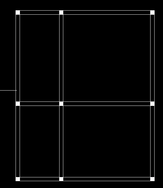
As shown above,the given plan in the question have to be modified.Where due to this,all the beams will be present in the straight line such that the lateral load transfer will be made easy and thus will reduce the shear failures of the beams.
Where the above is the major and the main alternative to be provided,where the first problems as mentioned above will be solved almost.
3)
Observations
- Floor Plan:We can find that the floor plan given in the question is not symmetrical and it not uniform also.This type of floor plans do come due to the plot limitations.As the plan is not symmetrical in both the directions,so,naturally any lateral load induced on the floor will not have the 100% influence in the same direction,so definitely a special lateral load resisting systme for these torsional moments should be accommodated.
- Internal Columns:The internal columns present in the building too don't follow any symmetry similar to the floor plan.And they too don't follow any specific mannher but out of the 5 columns,3 columns are in one axis while the remaining 2 columns are in other axis,so due to their random appearance of the columns in the floor plan,they may not take any lateral load efficiently,where the primary purpose of ther columns is just to carry gravity load alone of the building.
- Internal Walls:In the question,it was mentioned that the internal wall system will differ from the floor to floor.As the internal walls do provide as an important mass of the entire structure,it plays a key role in shear transfer from floor to slab to beam,where this will be proper when the elements are in order but in this case the elements are not in proper order which will lead to heavy distortion.
Suggestions
- We know that heavy torsional forces are generated,so that they have to be resisted by a respective lateral load system,so here the corner shear walls are suggested.
- We can even find that the floor is having greater area on the left side when compared to the right part,so the corner walls to be provided should be heavy on the left side such as to take take the heavy shear present on the left side due to less cross sectional area.
- As it was decided to provided the corner shear walls,the box typ foundation willbe suitable for the respective corner shear walls.And here the corner shear walls only be suitable as to resist the torsional moments generated in the structure and even under the architectural point of view they will be suitable.
- The internal columns can be provided with the isolated footings where ultimately these isolated footings have to be connected to the shear walls with the tie beams.