Conceptual design of a building with columns and shear walls
Q1)
The building shown, 20 × 35 m in plan, has columns on a 5 × 5 m grid and shear walls (with dimensions shown in m, 250 mm in thickness) in three alternative arrangements, (a), (b), (c), all with the same total cross-sectional area of the shear walls. Compare the three alternatives, taking into account the restraint of floor shrinkage, the lateral stiffness and the torsional one with respect to the vertical axis, the vertical reinforcement required for the same total flexural capacity at the base, the static eccentricity, the system’s redundancy, foundation systems, architectural constraints etc.
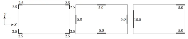
ans) In the first and second figure we can see that all the four shear walls are symmetrically placed and
are uniform in size. because of this there will be uniform distribution of seismic forces.
in the 3rd figure ,walls are dissimliar and are non symmetric, in this case,the walls which are more
strong will yield first and impose rest of their deflection pattern on the other.
in the first figure,walls are placed in L shape. because of this heavy biaxial stresses will be imposed
on them. and because of heavy stresses ,the floor below these walls will undergo heavy deformation.
therefore we can say that the floor shrinkage of the plan in first figure undergoes heavy shrinkage.
in the second figure we can see that all the four walls are symmetrically placed,
therefore there will be no heavy floor shrinkage for these walls as they are regularly placed and are safe.
in the 3rd figure ,there will be heavy deformation under large wall which is 10m,which is heavier
compared to the other two. because of this the floor shrinkage of this wall will be higher.
lateral stiffness of first figure will be higher due to heavy stresses. where as the lateral
stiffness of second figure will be less as stresses are less and lateral stiffness will be high for heavy wall
in 3rd figure compared to the other two walls.
similarly the torsional stiffness of the first figure will be higher compared to the other two as it
is directly proportional to the stresses, and torsional stiffness of 2nd figure will be lesser ,and it will
be higher in case of third figure.
since there is presence of shear walls in all the three figures, therefore redundancy will be high in
all of them ,but it will be higher in first figure followed by third and second figure.
in L shaped shear wall,vertical reinforcement is provided such that the spacing between all the vertical
bars is kept uniform i.e 2 inches,where it is kept 6inches for the last two bars from either sides,i.e for the
first figure, where it is kept unifrom for rectangular walls in the other two figures.
strip founfation is provided to all the three walls shown here.
in the first figure, there is no architectural disturbance to the building as the walls are L shaped
and in the other two figures, they are on the front face, so to some extent they contribute to the architectural
constraints of those plans.
shear walls carry the earthquake load down to the foundation. structure has great strength and stiffness in
the direction of their orientation.
Shrinkage For most designs shrinkage in the longitudinal direction can be ignored. However, that may not be the case
for perpendicular to grain shrinkage. Accumulated effects in the boundary chords of shear walls can degrade the
performance of the shear wall system and may need to be addressed with shrinkage compensating devices.
Question 2:
Discuss the suitability for earthquake resistance of the moment resisting framing plan of a three-storey building depicted here (cross-sectional dimensions in cm), the eccentricity of the centre of mass (as centroid of floor plan) to the centre of stiffness (from the moments of inertia of the columns) are shown. Suggest an alternative. Also, is there torsional flexibility? Are the two fundamental translational modes of vibration larger than the fundamental torsional mode of vibration. Discuss qualitatively.
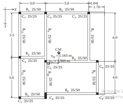
ans) in this figure, the frames are not continous and symmetric and one of the column is not unifrom.
and because of irregularity of frames ,from earthquake point of view it not safe due to lack of redundancy and
it will suffer from load multiplicity, fewer plastic hinges and less cost effective use of concrete.
if there is termination at the beam column joint ,then there will be no uniform transfer of internal
stresses. and in this layout ,only the top frame beam is continous,and in the bottom two frames there is
column at the joint,i.e there is termination at one end,and then after termination a new beam is laid.
these kind of arrangements make a lot of problems on the site, hence they should not be preferred
and we can see in the beam B7 only one end is supported by column, where as the other is left to be
supported by beam, this kind of arrangement is not permissible because it may lead to soft storey.
in this plan column 8 and beam 6 centres should coincide with each other, if they do not coincide
it will lead to torsion. and the maximum permossible eccentricity is given by b/4, and it should not
be more than that according to code provisions.
there is chance of torsional flexibility in the building as we can see that there is a room in the plan
which is extending outside the plan , and if the lateral force acts on this area there will be rotation insome parts
of the building.
fundamental translational mode of vibration is larger than fundamental rotational mode of vibration
because translational mode is due to the irregularity or discontinuity of frames
from earthquake point of view it not safe due to lack of redundancy and
it will suffer from load multiplicity, fewer plastic hinges and less cost effective use of concrete.
since there are two frames which are irregular where as if we see the rotation or torsion is only
due to the torsional flexibility in the building as we can see that there is a room in the plan
which is extending outside the plan , and if the lateral force acts on this area there will be rotation insome parts
of the building. as there is only one source of damage due to rotation and two for translational in the form
of frames, hence translational mode of vibration will be higher.
Q3)
A multi-storey building with basement, with a quadrilateral (non symmetrical floor plan) plan as, has interior columns in an irregular (not in a grid) pattern in plan that serves architectural and functional considerations. Partition walls and interior beams supporting the slab have different layout in different stories. However, there is no constraint to the type, location and size of the lateral force resisting components and sub-systems on the perimeter. Proposals are to be made and justified for the choice of the lateral-load-resisting system and its foundation.
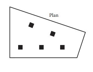
ans) in this layout, raft foundation is provided to the entire layout and columns are irregularly placed.
first of all ,for bottom three columns we can provide a straight plinth beam, and also for the upper
two columns. now to provide the beam to the right and left side of the layout, we have to change the
shape of the rods in the reinforcement as per the layout,i.e curve shaped. after providing the plinth beam
masonry walls can be raised straight to the top 2 and bottom 3 columns. and for the right and left side of the
layout walls can be raised in the form of arch,i.e curve shaped. after completing the walls again a beam will
be placed similar to the pattern of plinth beam at the top of walls. similarly the slab can be laid as per the
shape of layout.