Conceptual design of a building with columns and shear walls
Question 1:
The building shown, 20 × 35 m in plan, has columns on a 5 × 5 m grid and shear walls (with dimensions shown in m, 250 mm in thickness) in three alternative arrangements, (a), (b), (c), all with the same total cross-sectional area of the shear walls. Compare the three alternatives, taking into account the restraint of floor shrinkage, the lateral stiffness and the torsional one with respect to the vertical axis, the vertical reinforcement required for the same total flexural capacity at the base, the static eccentricity, the system’s redundancy, foundation systems, architectural constraints etc.
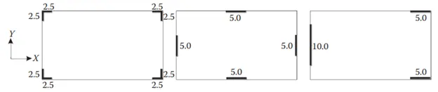
Ans: In Figure 1:
Restraint to Floor Shrinkage: Restraint to shrinkage will be more in this due to position at corners and this lead to more cracks formation.
Lateral stifness: lower lateral stifnees ,then 2due to shear wall arrangments in corners in both X and Y direction.
Torsion with respective Vertical Axis: corner wall provided more resistant to twist.
Vertical reinforcement for similar base capacity: Nominal flexural movement and heavy twisting and due to this required second largest reinforcement between the three arrangments.
Figure 2:
Restraint to Floor Shrinkage: Restraint to shrinkage will be average,as the positon of shear walls are in the middle and due to this these is least possibility of formation of cracks.
Lateral stifness: More lateral stifness due to uniform distribution in both x and y direction.
Torsion with respective Vertical Axis: Edge walls provide less resistance to twist then previous.
Vertical reinforcement for similar base capacity: Normal twisting movement and due to this require least reinforcment.
Figure3:
Restraint to Floor Shrinkage: resitant to shrinkage will be less due to unsymentrical arrangment and due to this crack will be less too.
Lateral stifness: Non -uniform arrrangement which leads to non- uniform lateral stiffness.
Torsion with respective Vertical Axis: Irregular position tends to very poor resistance to twist.
Vertical reinforcement for similar base capacity: Heavy both flexural and twisting movemet due to irregular positioning and due to this require more reinforcement.
In figure1:
Static eccentricity:symentric and c.g coincedens along the plane therefore no assentricity.
system redundancy: since the rc wall is less effective to collect lateral forces. The frame dtructure will need to take part in lateral load resisting system.
Foundation system:Box footing with tie beam arrangement is suitable for this system.
Architectural constraints:architecturally very effective, since only corners are obstructed.
In figure 2:
Static eccentricity: symentric and c.g coincedence along the plane therefore no assentricity.
system redundancy: Rc wall system is effective in this case and mirror with right angle .They opposses good redundancy.
Foundation system:Isolated foundation is suitable for this system.
Architectural constraints: architecturally may not be recomended since all four sides entrances are partially obstructed.This Rc wall arrangment may distrub open space requirement.
In figure3:
Static eccentricity: centre of madss tends to move towards y direction more due to irregualr symentry therefore more eccentricity.
System redundancy: The system is worst in terms of redundancy because of concentration of loads at sites.
Foundation system: Trip footing for y direction RC wall and isolated footing for X direction RC wall is suitable.
Architectural constraints: Left side is completely arrested. all other side are ok with respect to architectural point of view.
Question 2:
Discuss the suitability for earthquake resistance of the moment resisting framing plan of a three-storey building depicted here (cross-sectional dimensions in cm), the eccentricity of the centre of mass (as centroid of floor plan) to the centre of stiffness (from the moments of inertia of the columns) are shown. Suggest an alternative. Also, is there torsional flexibility? Are the two fundamental translational modes of vibration larger than the fundamental torsional mode of vibration. Discuss qualitatively.
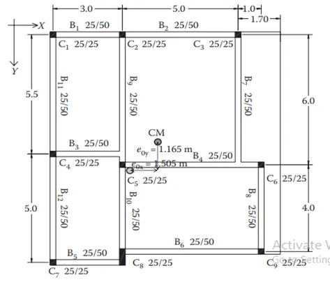
ANS: In seismicc point of view, the lateral load transfering mechanism from floor to foundation is effeciently dealt in the given structural drawing.Even though it is just 3 storey building any moderate earth quake will effect this structure due to its complexity in load transfering mechanism.The given figure is of weak columnand strong beam.Example It has more eccentricity than in y direction than in x direction as shown in the fig:(ey=1.65> ex=1.505).
INCOMPLETE LATERAL LOAD TRANSFER IN X-DIRECTION.
INCOMPLETE LATERAL LOAD TRANSFER IN Y-DIRECTION.
Alternative structural framing:
With effect arrangments of column, we shall avoid the complexity in load paths. also we can acheive the beam framing from column to column,which will help easiest flow of lateral forces.
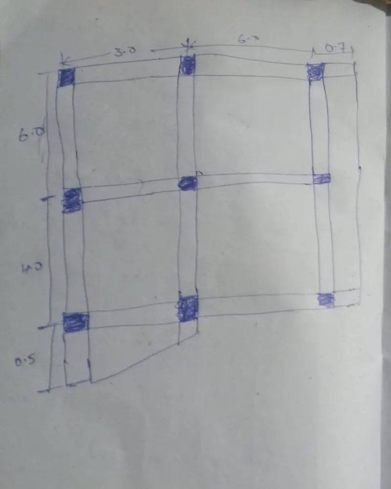
Just by shifting right the top column and left bottom columns the beams scheme is effeciently revised from column to column . This resemble the grid pattern of floor which will expert better resistance for lateral loading.
Torsional inpact of building:since the centre of mass and centre of stiffness of the building in not coinciding , the building will definetly experience torsional with respective vertical axis. still, the plan aspect ratio is less than 3.(with in th limits IS1893),by which we may assumue the given system will be proportioned.
Also the given floor structural system is not effective in transforning lateral loads to vertical elements due to too much offset and beam to beam connection. The response of the building in fundemental mode of translation is worst.
The two fundemental modes of translation may be still higher than the fundemental mode of torsion.
Question 3:
A multi-storey building with basement, with a quadrilateral (non symmetrical floor plan) plan as, has interior columns in an irregular (not in a grid) pattern in plan that serves architectural and functional considerations. Partition walls and interior beams supporting the slab have different layout in different stories. However, there is no constraint to the type, location and size of the lateral force resisting components and sub-systems on the perimeter. Proposals are to be made and justified for the choice of the lateral-load-resisting system and its foundation.
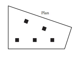
ANS:As per plan dimensions,we can understand that the centre of mass will situate on the left side portion of the floor plan, as the area of the floor is larger on the left side .so we have to position of the lateral load resisting system is such a way their stiffness centre should come near to the centre of mass this is mandatory to avoid torsional irregularity.
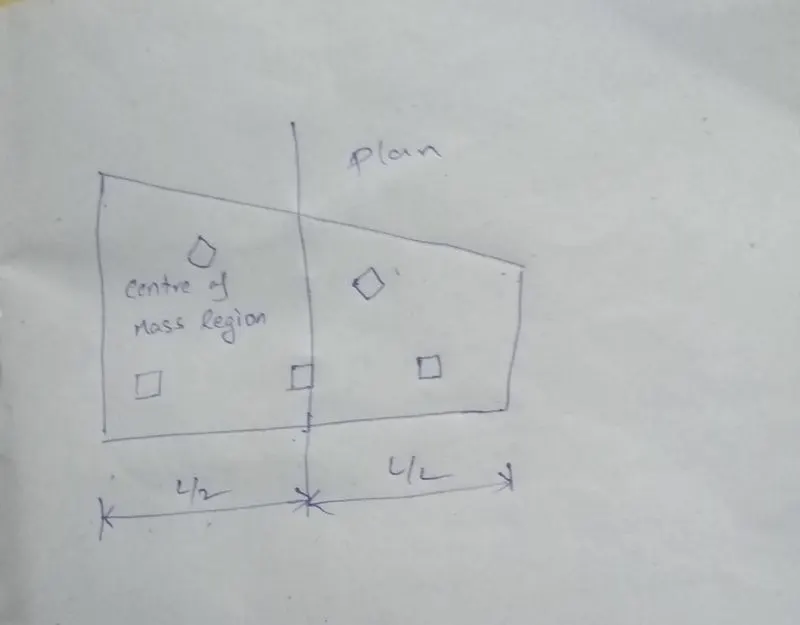
The suitable lateral load resisting system:since the floor plan is irregular quandrentral, the influence of x-direction earth quake will also have effectie in y- direction and vice versa .So the lateral load resisting system which should bidirectional strength to seismic forces.so we can suggest L- shaped corner RC wall arrangment.
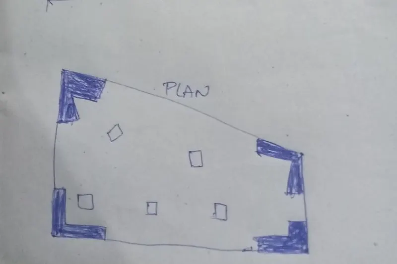
Fot these L- shape Rc corner wall irregular corner arrangmentw can go with two possible foundation optios.
1.isolated footings with tie beam connnection.
2. whole box type foundation
out of which box type foundation is preferable.