CHT Analysis on Exhaust port of a cylinder in an Engine
Aim: CHT Analysis on the exhaust port of a four strokes four-cylinder engine in the Ansys Fluent
The following parameters have been studied and calculated in the current project.
1. Temperature distribution
2. Analytical solution of heat transfer coefficient using Dietus Bolter Equation
3. Velocity Countour and velocity streamline in the given region
4. Pressure in the given region
CHT Analysis and its Importance
CHT analysis, often referred to as Conjugate Heat Transfer analysis, is a computational technique used in engineering and physics to study the simultaneous conduction, convection, and radiation heat transfer in systems where both fluid flow and solid structures are present.
Applications:
- Internal Combustion Engines: CHT analysis is extensively used in the automotive industry to study the heat transfer between the combustion gases, engine block, and coolant. This is crucial for designing efficient and reliable engines.
- Gas Turbines: In aerospace and power generation industries, CHT analysis helps in optimizing the design of gas turbine components by understanding the heat transfer between hot gases and the turbine blades or vanes.
- Electronics Cooling: In electronic devices, such as computers, smartphones, and other electronic equipment, CHT analysis is employed to ensure that components stay within safe temperature limits. It helps in designing effective cooling systems like heat sinks and fans.
- Nuclear Reactors: CHT analysis plays a critical role in the design and safety assessment of nuclear reactors. It helps in understanding the heat transfer between the coolant and the reactor core.
- Renewable Energy Systems: In solar collectors, wind turbines, and geothermal systems, CHT analysis is used to optimize the transfer of thermal energy and ensure system efficiency.
- Chemical and Process Industry: CHT analysis is crucial for the design and operation of chemical reactors, heat exchangers, and other equipment where heat transfer is a key factor.
Importance:
- Predicting and Preventing Failures: Understanding heat transfer is crucial for preventing overheating and thermal stress in components. This is particularly important in high-temperature applications like jet engines or industrial furnaces. For example, lets take the example of Internal Combustion Engines - The internal combustion engine industry is moving toward simulating the entire system rather than independent components. The accuracy of the predicted combustion in the cylinder is dependent on the temperature boundary conditions in the cylinder. By considering heat transfer in the metal components (e.g., the cylinder head, liner, piston, etc.), the cylinder wall no longer has a user-specified temperature, but instead has temperatures predicted as part of the complete-system simulation. This makes the overall simulation results more predictive by reducing the dependence on assumed boundary conditions.
- Safety Considerations : By predecting the parameters like tempertaure, pressure etc, the safety of all the individual componenets is ensured.
Modelling Approach
There are two cases performed for simulation
1. Baseline simulation in which default mesh in the Ansys Fluent is taken and the flow is simulated
2. Mesh is refined further by adding Inflation layer between the fluid and the solid component and then, the flow is simulated.
Lets study both the cases in detail and plot our observations:
Csae 1: Baseline simulation (Default meshing in Ansys Fluent)
Geometry:
1. Geometry is created in the spaceclain of appropriate dimensions.
2. Fluid Volume and solid component are extracted from the geometry and moved to the new component and named as final geometry.
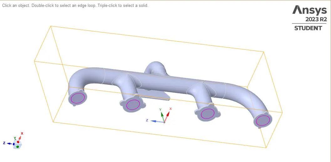
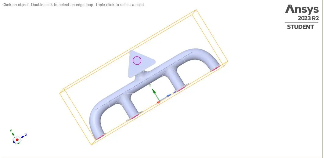
3. Share topology needs to be share to avoid non-conformal mesh.
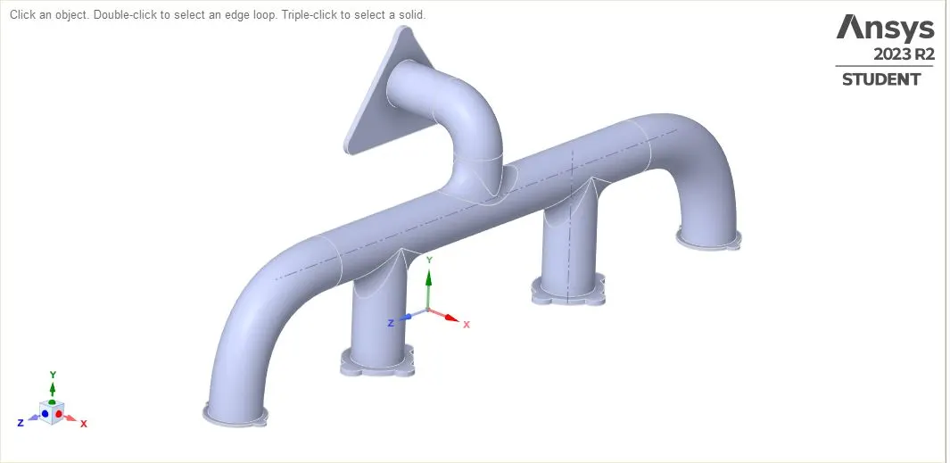
The pink round will be seen on the geometry which indicated that both fluid and solid volumes have been shared so that there should not be the problem of non-conformal mesh durin the time of meshing.
Meshing:
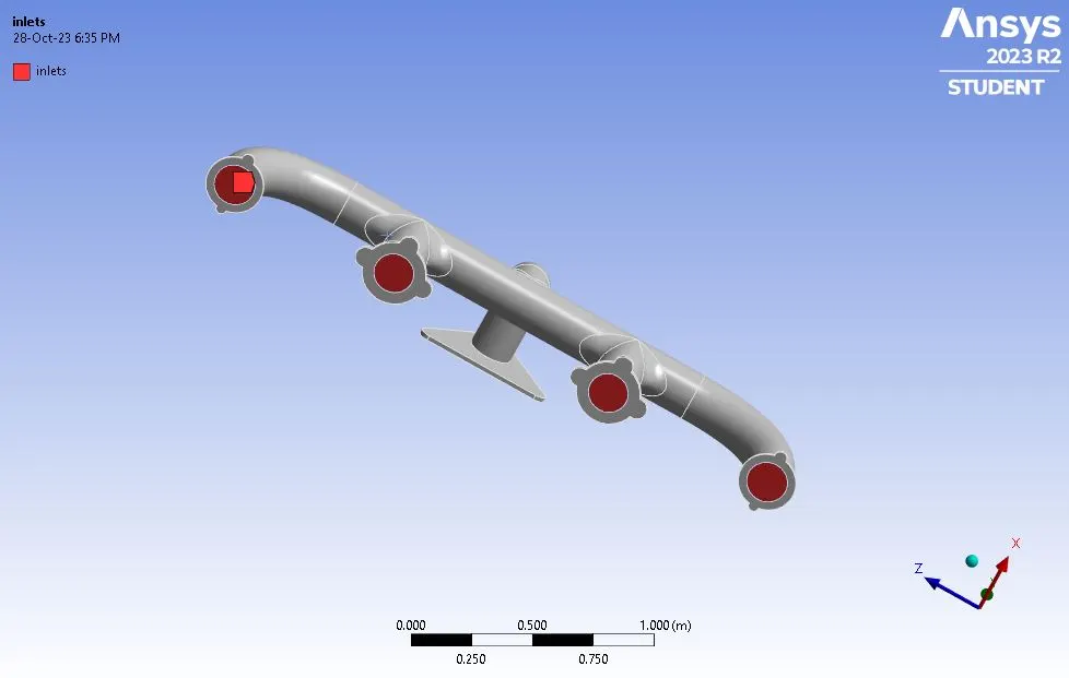
Named selection:
inlets
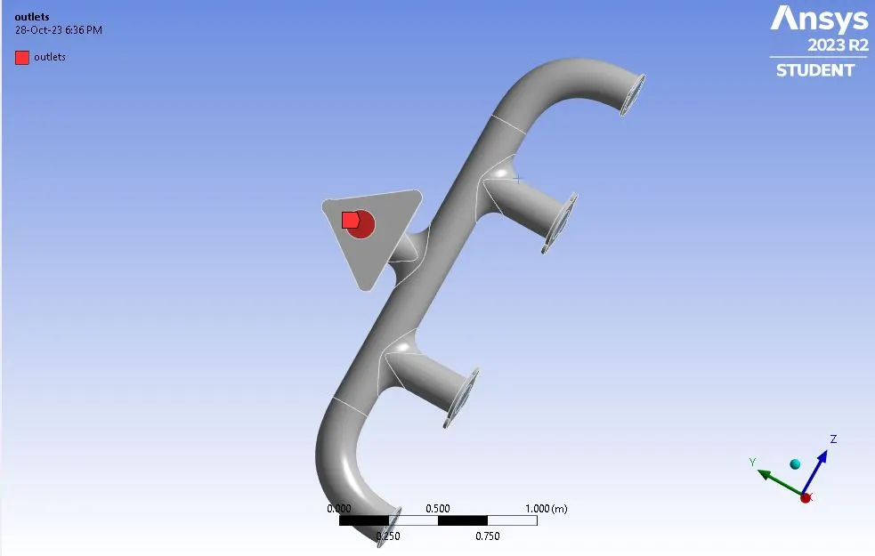
outlet:
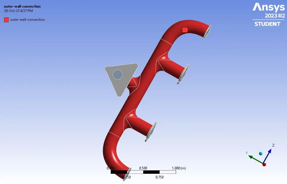
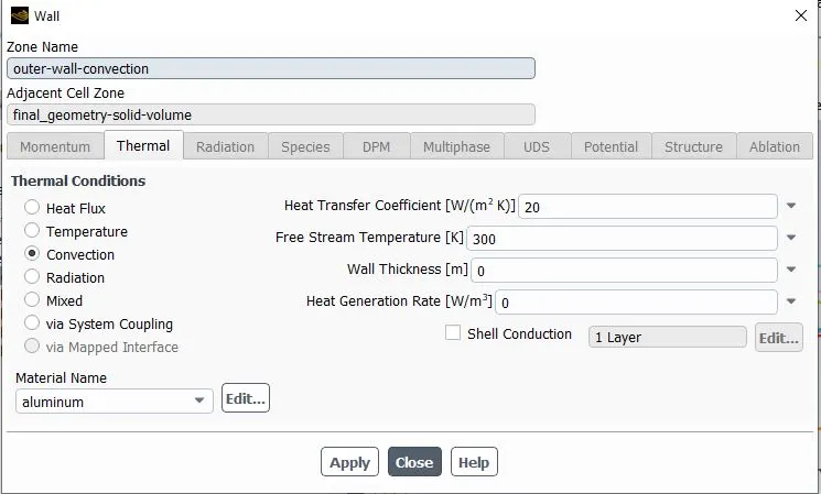
outer wall convection:
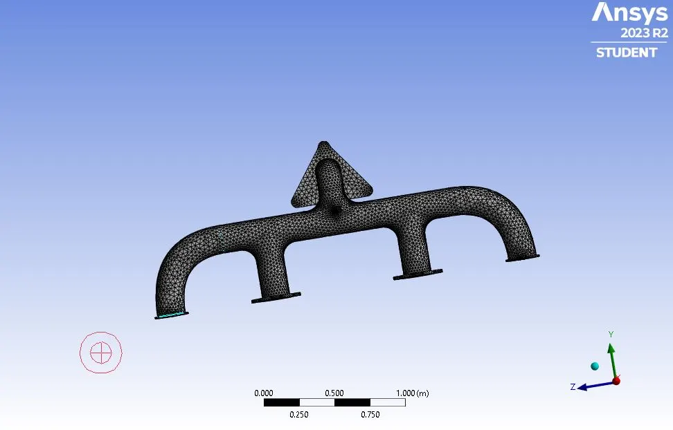
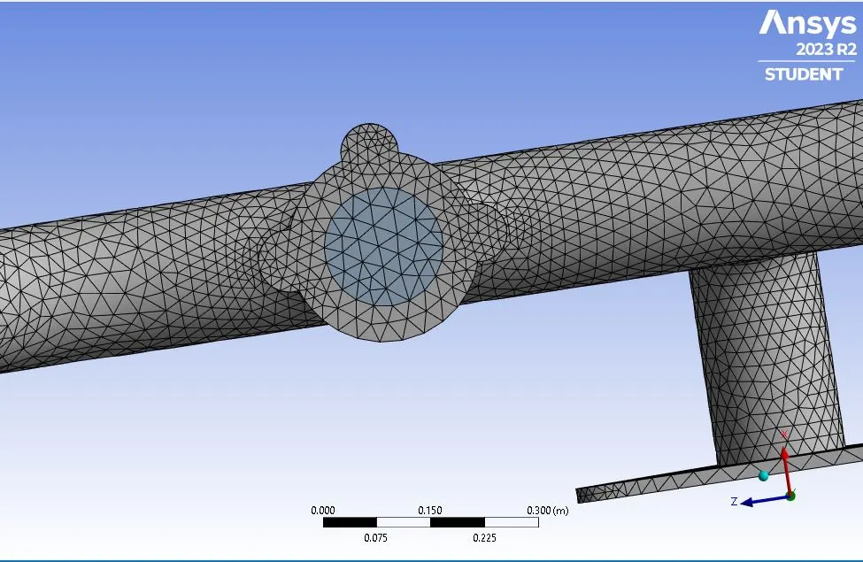
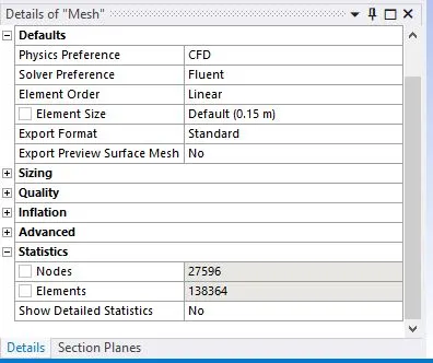
Generating mesh:
Set-up in Flunet:
heat transfer coefficient, h = 20 w/m^2-k .
Materials properties-
Fluid name = air.
Density = 1.225 kg/m^3
Specific heat = 1006.43 J/kg-k
thermal conductivity = 0.0242 w/m-k
viscosity = 1.789e-5 kg/m-sec.
Solid -
the solid material is aluminum
Specific heat = 871 J/kg-k .
Thermal conductivity = 20 w/M-k
The following snips are added here to demostarte the processes involved in the Fluent:
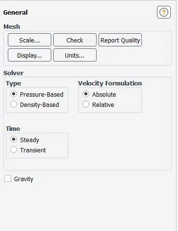
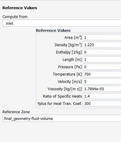
K-epsilon turbullence model is used as this is the internal flow problem.

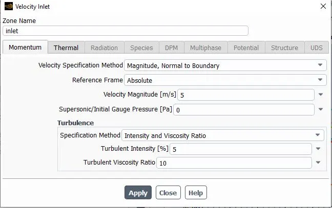

Hybrid Initilization is done before the calculation is done

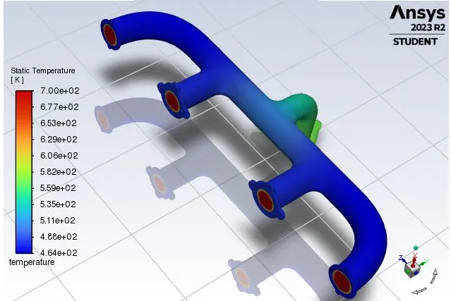
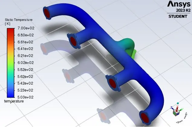
Temperature distribution in the fluent
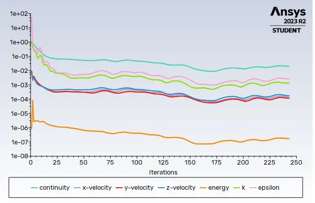
Residual

CFD Post:
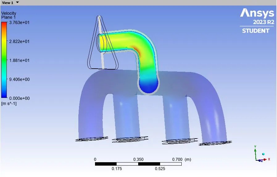
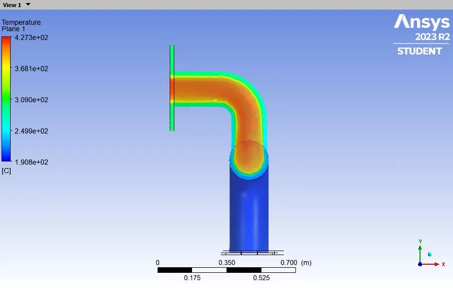
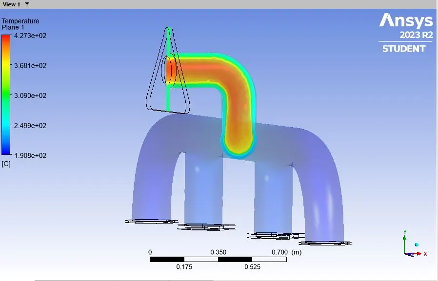
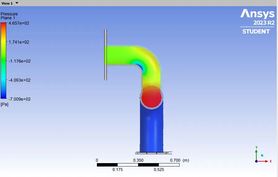
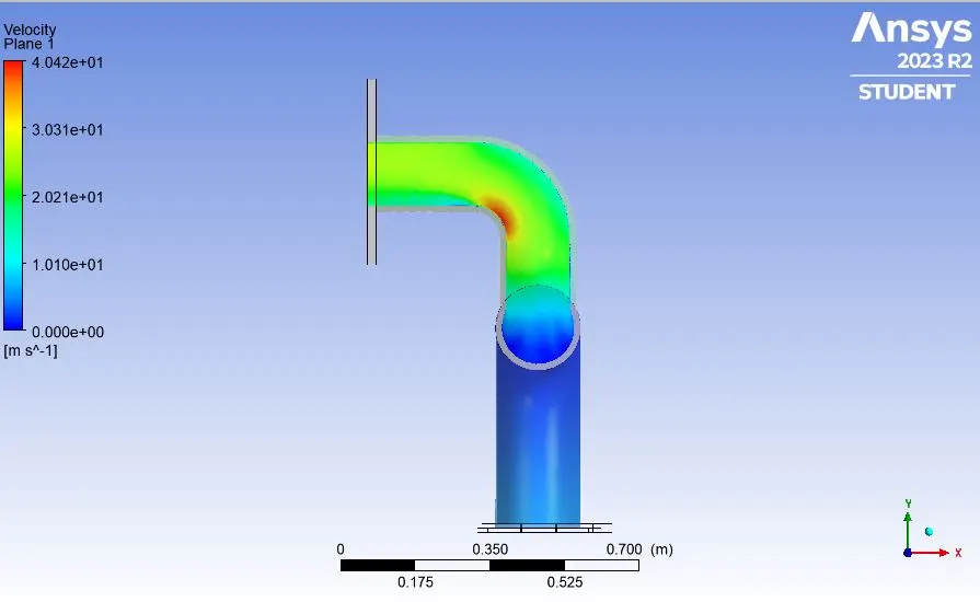
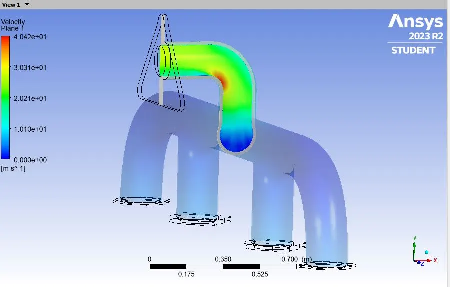
A XY plane is created to study the different parameters like temperrature, velocity and pressure in the appropriate region.
The following contours are recorded in the CFD post.
Velocity contour:

Velocity contour (Side view):
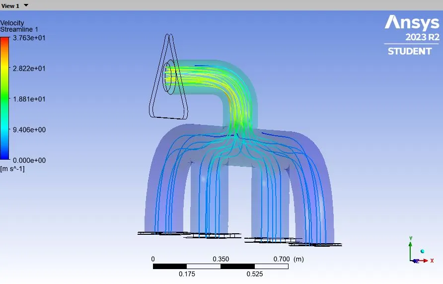
Velocity Stream:
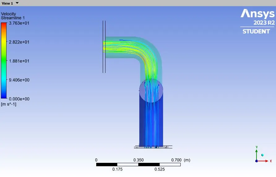
Velocity Stream (side view):
Temperature Contour:
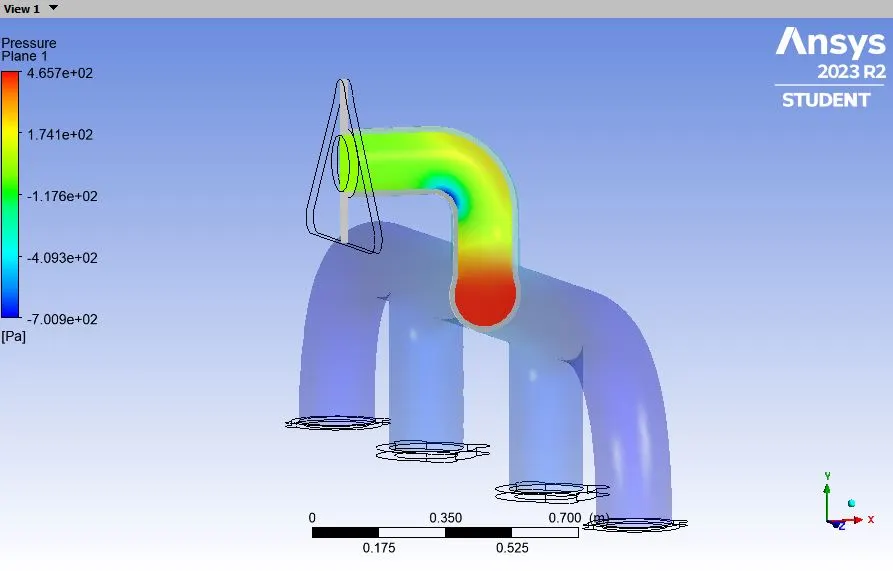
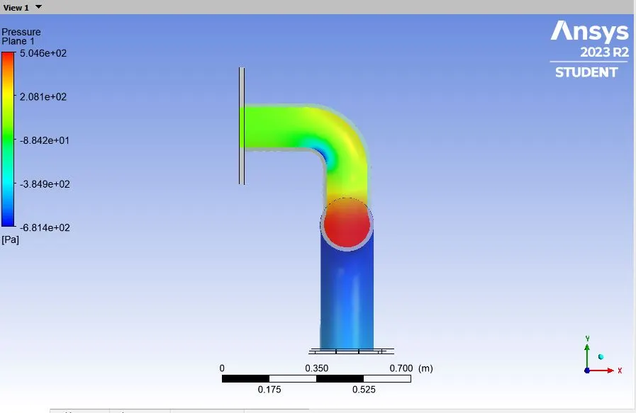
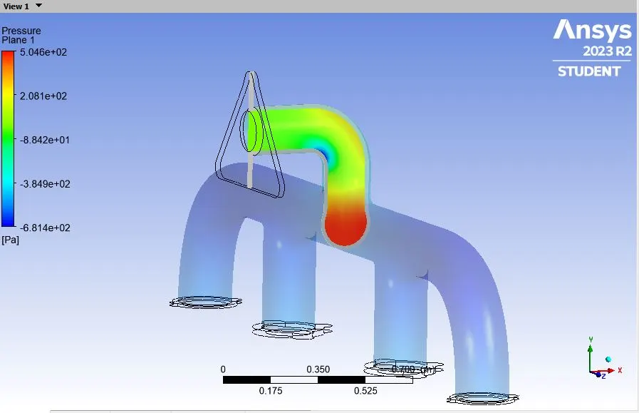
Pressure contour
Csae 2: Refined case simulation (Addition of inflation layer)
Geometry: Geometry remains as it is as it was in the previous case 1 of base simulation.
Meshing:
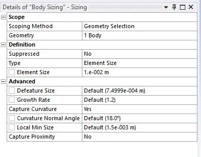
Inflation layer is added and Body sizing is done to reduce the size of the solid component
Initially, the size of the solid component is taken as 150 mm and then its reduced to 10 mm in the refined case (second case).

Inflation layer
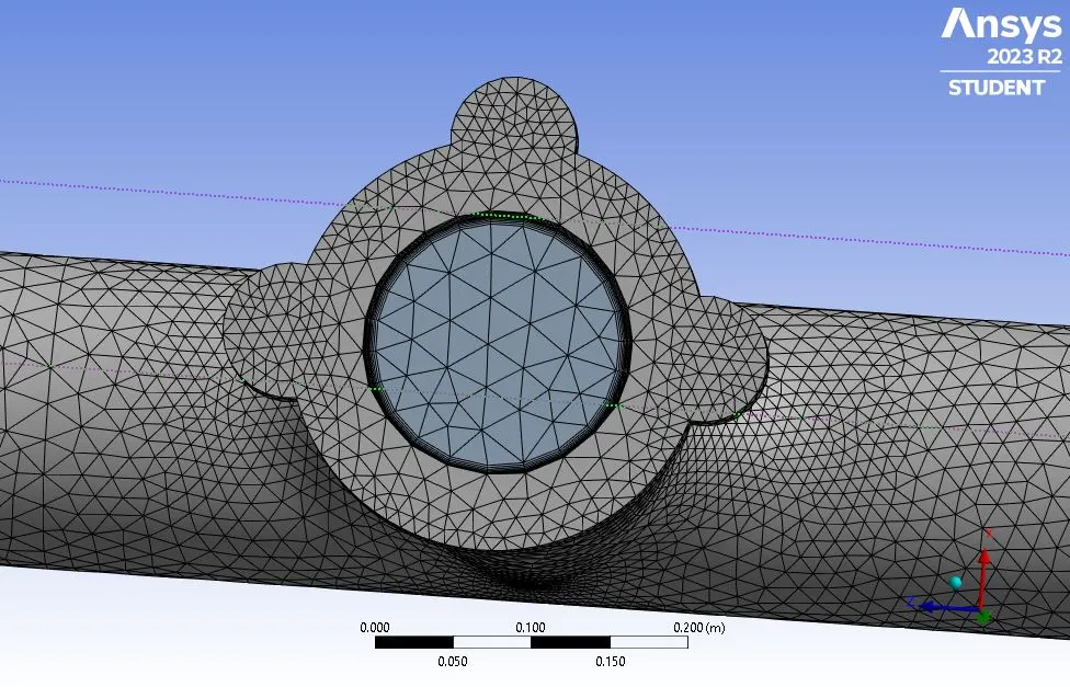
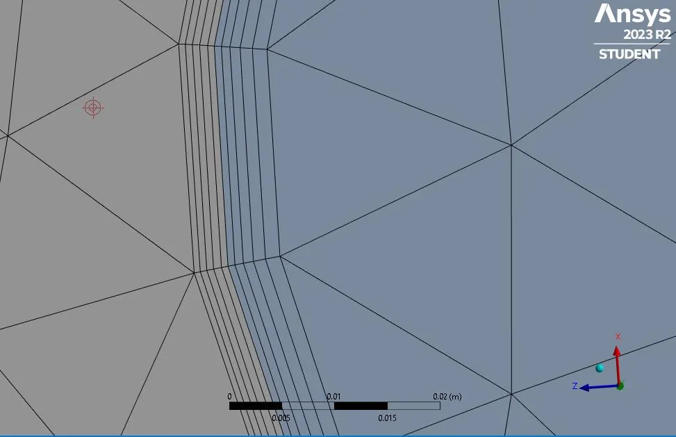
The total number of cells in this case is 371918 which acn be seen in the following figure.

Set-up in Flunet: All the setup in fluent is kept same as the previous set up for the base simulation
Resudulas:
CFD post:
Velocity contour:
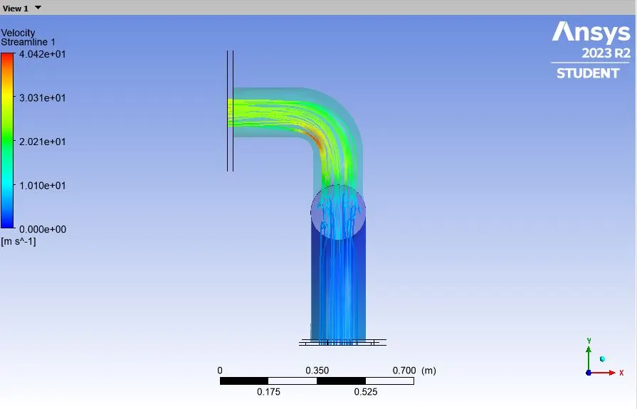
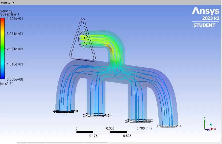
Temperature contour:
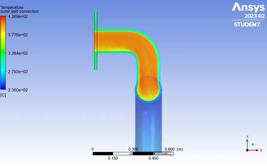
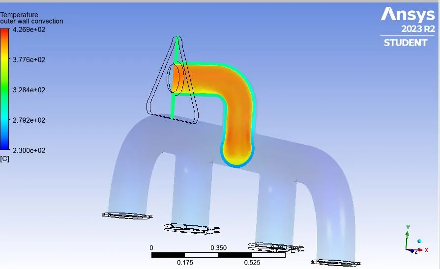
pressure contour:
Analytical solution-
In the analysis, the heat transfer coefficient is taken as h = 20 w/m^2-k
Now, the analytical value of the heat transfer is calculated using Dittus Bolter Equation,
The Reynolds number of the flow is of Re = 56867.66 considering the flow velocity = 5 m/sec
By using the Dittus Bolter heat transfer coefficient relation in natural turbulent flow, the Diltus Bolter HT coefficient is determined by the Nusselt number which is related by the formula of
Nu(D) = 0.023* Re^(4/5)*pr^n,
here n = 0.3
D = diamter of the pipe
the prandtl number is caluclated using the followinh formula:
pr = mu*cp/k, here mu = 1.789*10^-5 cp = 1006.43 J/kg-k and k = thermal conductivity = 0.0242 w/mk
pr = (1.789*10^-5*20)/0.0242 = 0.744
the Nusselt number is calculated as NUd = 0.023*56867.66^(4/5)*0.744^0.3 = 131.792
Nud = hD/k = 131.792 = h*0.166/0.0242
so h = 19.52 w/m^2k.
Repots and Set-up:
https://drive.google.com/drive/folders/11qPJocn3yF9_iVTLfjoDIoL_XedBH4mQ?usp=sharing