External flow simulation over an automobile passenger car 'Ahmed body'
Aim: Aerodynamics study (External flow simulation) on the model of an automobile passenger car "Ahmed body" using Ansys Fluent
Objective: This project's goal is to calculate the drag and lift coefficients and run the grid independence test on the Ahmed body to measure the aerodynamic forces acting on it.
The expected results will include:
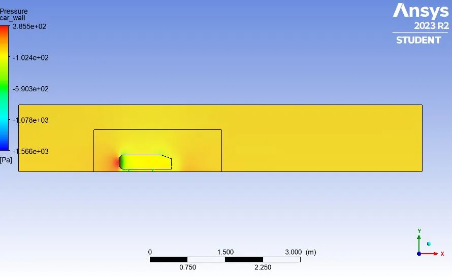
1. Velocity and pressure contours.
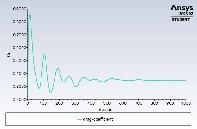
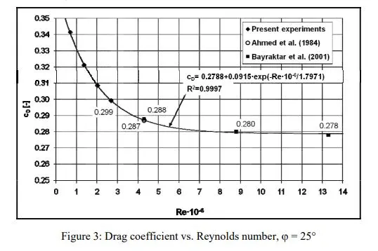
2. The drag coefficient plot for a refined case. ( For a velocity of 25m/sec, the drag coefficient should be around 0.33 - taken from a reference paper).
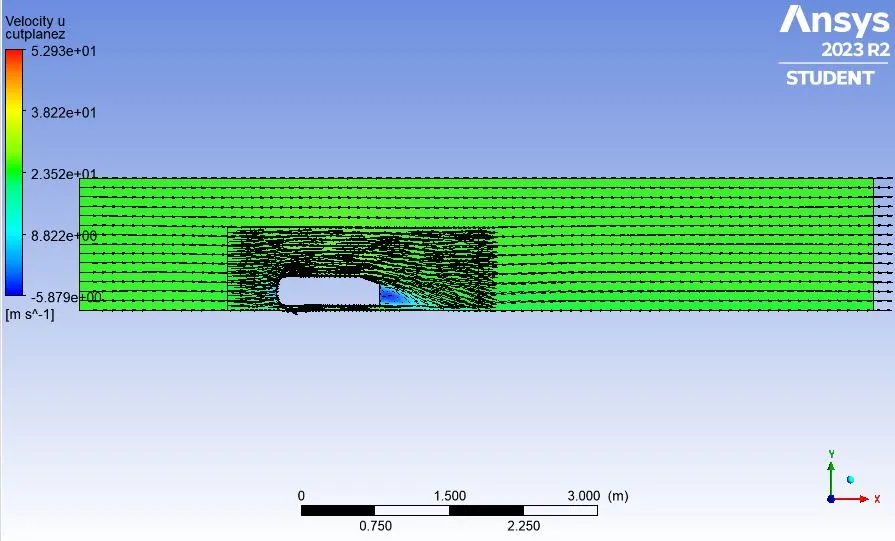
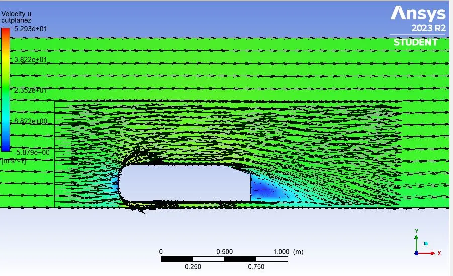
3. The vector plot clearly showing the wake region.
4. Performing the grid independence test and providing with the values of drag and lift in each case.
Fo this challenge, answers to the following questions need to be addressed.
Q1. Describe Ahmed's body and its importance.
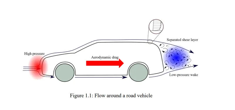
Q2. Explain the reason for the negative pressure in the wake region.
Q3. Explain the significance of the point of separation.
Answers:
What is Ahmed body? Also describe its importance.
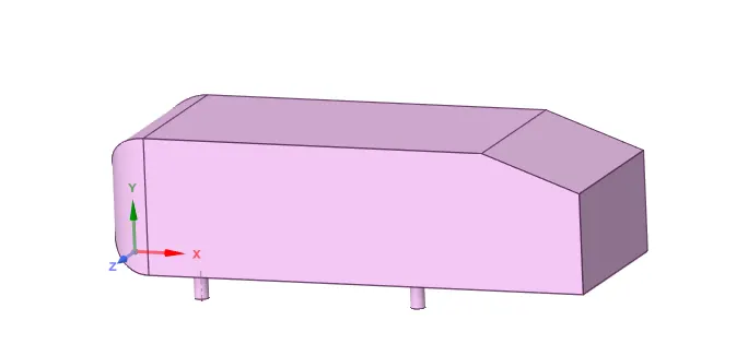
Ahmed body, also known as the Ahmed model or the Ahmed body shape, is a simplified aerodynamic model used in automotive engineering to study the aerodynamic characteristics of passenger cars. It was developed by Ahmed F. Ahmed in the late 1970s. The Ahmed body is a geometric representation of a simplified car shape designed to replicate the flow patterns around a real car.
The Ahmed body is of significant importance in the field of automotive aerodynamics for several reasons:
- Simplified Representation: The Ahmed body provides a simplified geometric representation of a passenger car. This simplicity makes it easier to conduct controlled experiments and gather fundamental data on the aerodynamic behavior of vehicles.
- Rear-End Aerodynamics: It is particularly valuable for studying the effects of different rear-end configurations on aerodynamic performance. This includes understanding flow separation, vortex shedding, and drag reduction techniques related to the rear of a vehicle.
- Cost-Effective Testing: Constructing and testing a full-scale vehicle in a wind tunnel can be expensive and time-consuming. The Ahmed body offers a cost-effective alternative for preliminary testing and analysis of aerodynamic properties.
- Design Optimization: By using the Ahmed body, automotive engineers can make design modifications to improve the aerodynamic performance of vehicles. This can lead to benefits such as reduced drag, increased fuel efficiency, and enhanced stability at high speeds.
- Comparative Studies: Engineers can use the Ahmed body to compare the aerodynamic performance of different vehicle models or configurations. This allows for a systematic evaluation of design choices and can lead to insights into best practices.
- Research and Development: The Ahmed body is a valuable tool for researchers and automotive manufacturers to explore innovative design solutions. It helps in the development of new technologies and techniques to enhance the aerodynamic efficiency of vehicles.
- Compliance with Regulations: Meeting stringent emissions and fuel efficiency standards is a major concern for the automotive industry. Understanding and optimizing aerodynamics is crucial in achieving these regulatory targets.
- Improving Vehicle Safety: Aerodynamics also influence the stability and handling characteristics of a vehicle. Understanding how airflow interacts with the car's shape can lead to improvements in vehicle safety and stability.
- Reduction of Wind Noise: The aerodynamic design of a vehicle impacts wind noise. By studying the flow patterns around the Ahmed body, engineers can make adjustments to minimize noise levels.
Explain the significance of the point of separation.
The point of separation in fluid dynamics, also known as the separation point, is a critical aspect of understanding and analyzing the flow of fluids, including air around aerodynamic surfaces like wings, airfoils, and the bodies of vehicles.
Here are the key significances of the point of separation:
- Transition from Attached to Separated Flow: The point of separation marks the location where the airflow transitions from being smoothly attached to the surface (laminar or turbulent boundary layer) to becoming separated from the surface. This separation is often accompanied by the formation of vortices and turbulence.
- Lift and Drag Generation: Understanding the point of separation is crucial for controlling lift and drag forces on objects in a fluid flow. For example, in aerodynamics, controlling the point of separation on an airfoil can significantly impact its lift and drag characteristics, which are crucial for aircraft performance.
- Drag Reduction: Reducing separation and maintaining attached flow can lead to lower drag coefficients. This is particularly important in the design of vehicles where minimizing aerodynamic drag improves fuel efficiency.
Explain the reason for the negative pressure in the wake region.
The flow behind an object separates from the surface and creates a highly turbulent region behind the object, called the wake. The pressure inside the wake region remains low as the flow separates and a net pressure force (pressure drag) is produced. In other words, due to the production of pressure drag being produced from flow separation, the pressure in the wake region is low. This is what is causing the vacuum.
Modeling approach followed
Baseline simulation approach using k−ε model.
- Ahmed's body is loaded into the Space claim.
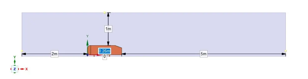
- A single enclosure is drawn across Ahmed's body.
- Now the geometry is loaded for meshing.
- A baseline simulation is set up with the default element size of Ansys (413.6 millimeters).
- A named selection is created for the enclosure viz; inlet, outlet, symmetry.
- To create the named selection for the car the enclosure faces are hidden and box select is selected from the meshing toolbar and (car wall) name is given to it.
- Ansys Fluent window is opened and the geometry is loaded.
- Steady-state, the density-based solver is selected.
- Reference values are updated as per the prescribed conditions.
- In the inlet boundary condition, inlet velocity is 25 m/s and 300K temperature are set.
- Drag-coefficient plot and lift-coefficient plot is created by setting the reference as (car walls).
- Hybrid initialization is selected.
- The solution is initialized by hitting t=0.
- The cut-plane-z is created along Ahmed's body.
- The velocity contour, pressure contour is created along the cut-plane-z.
- The animation video is created for the velocity contour.
- The simulation is executed for 1000 iteration.
Simulation with a finer mesh using k−ω-SST (Mesh refinement has been done for the two elemental sizes)
- The geometry is loaded into the Space Claim.
- The region of local refinement is created near Ahmed's body.
- As the body is perfectly symmetric, the simulation is executed by considering the only half body. This is the best practice where we can save on the number of cells and get the results faster as well.
- The geometry is loaded for meshing. The multizone method is selected for the outer enclosure to provide hexahedral mesh which provides accurate results in simulation.
- The element size for the first enclosure will be changed as (100mm and 80mm for the first mesh refinement and the second mesh refinement cases respectively), the element size for the second enclosure will vary as (50mm and 40mm for the first mesh refinement and the second mesh refinement cases respectively), the element size of the leg of Ahmed's body will be 5mm.
- The rest procedure is repeated as above
Preprocessing and the solver settings
Case-1: External flow simulation over Ahmed body by creating a single closure and using default mesh value of ANSYS-FLUENT
Turbulence model: k−ε
Ahmed body model
Creating an enclosure across Ahmed body
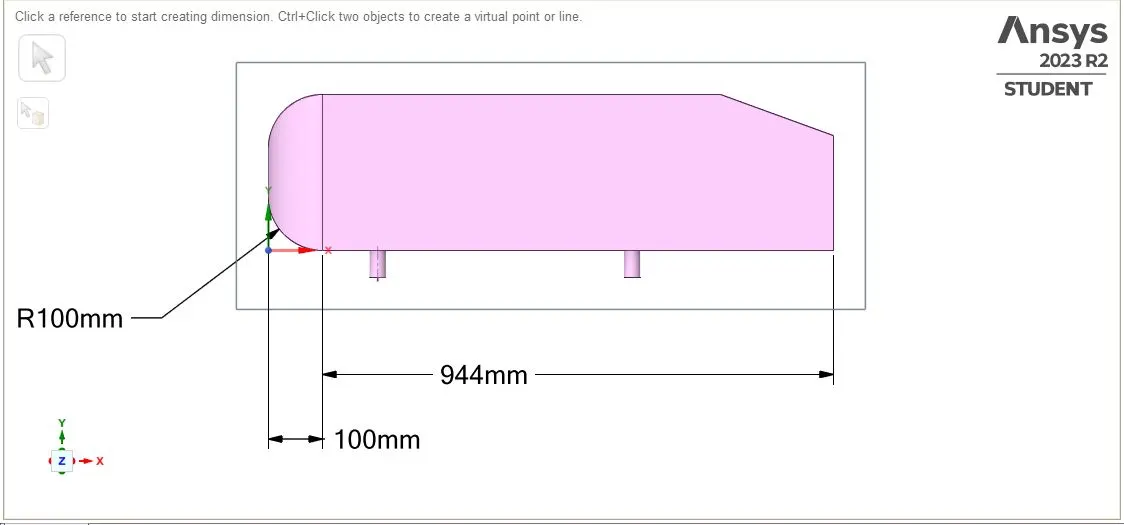
Dimensions of the Ahmed Body
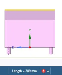
Default mesh size of Ansys-Fluent
Creating named selection to set up physics and boundary conditions.
Inlet boundary condition (velocity inlet).
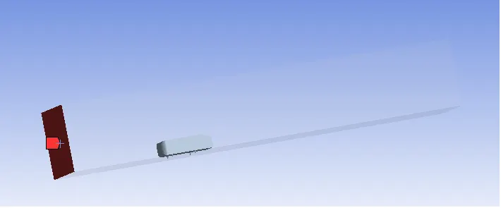
Outlet boundary condition (pressure outlet)
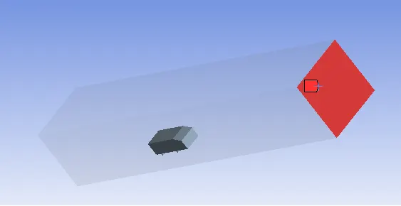
Symmetry boundary condition
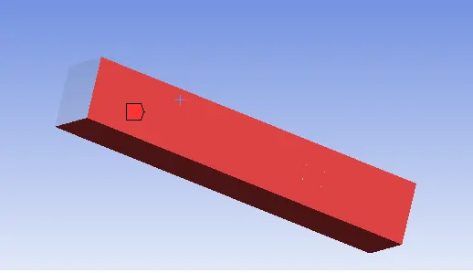
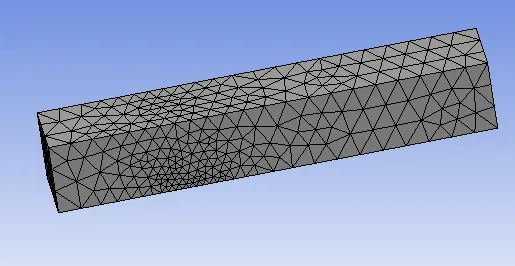
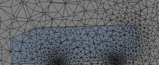
Performing meshing with default mesh size in ANSYS-FLUENT
Element size: 0.4136 m
Number of elements: 84920
Setup in Fluent
Setting up Physics in the fluent is done and the relevant plots are captured:
Reference values:Projected Area=">==0.389⋆0.1635">0.389⋆0.288
0.389⋆0.1635=">==0.112032">0.056016 0.112032m2">m2�2
Length of the Bod = 1.044m
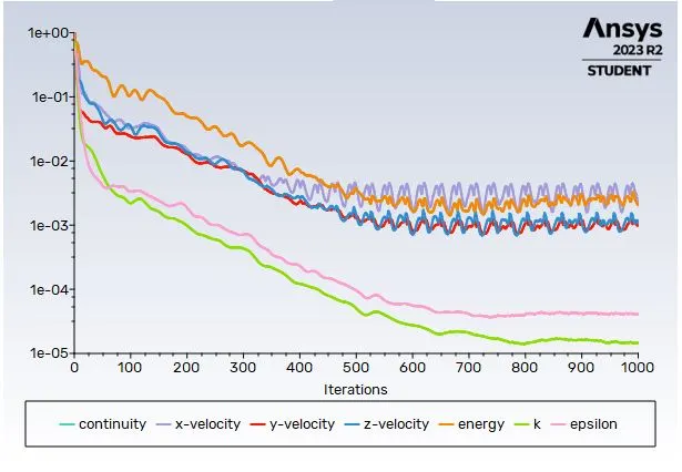
Residuals
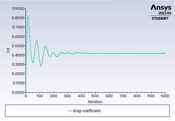
Coefficient of Drag
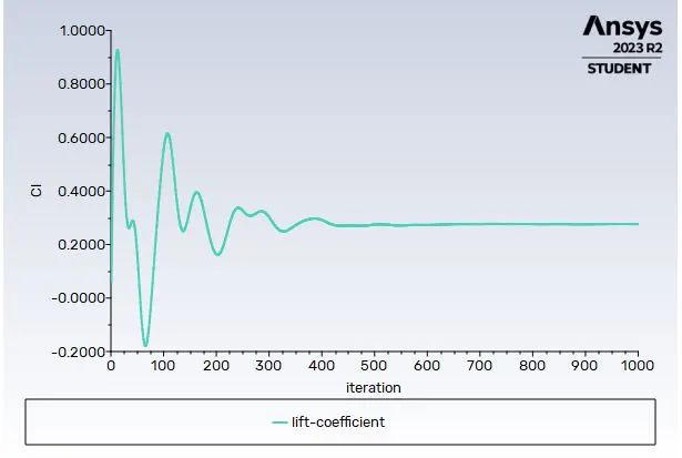
Coefficient of lift
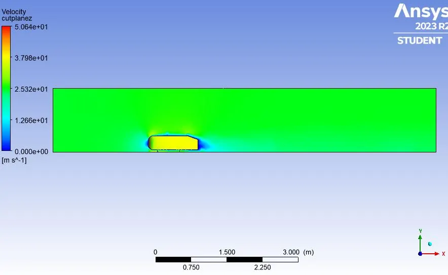
Velocity Contour
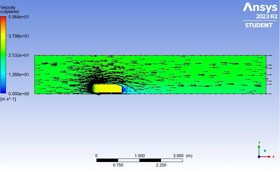
Velocity Vector contour
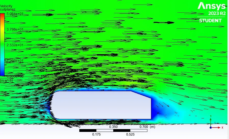
Velocity Vector contour(Zoomed)
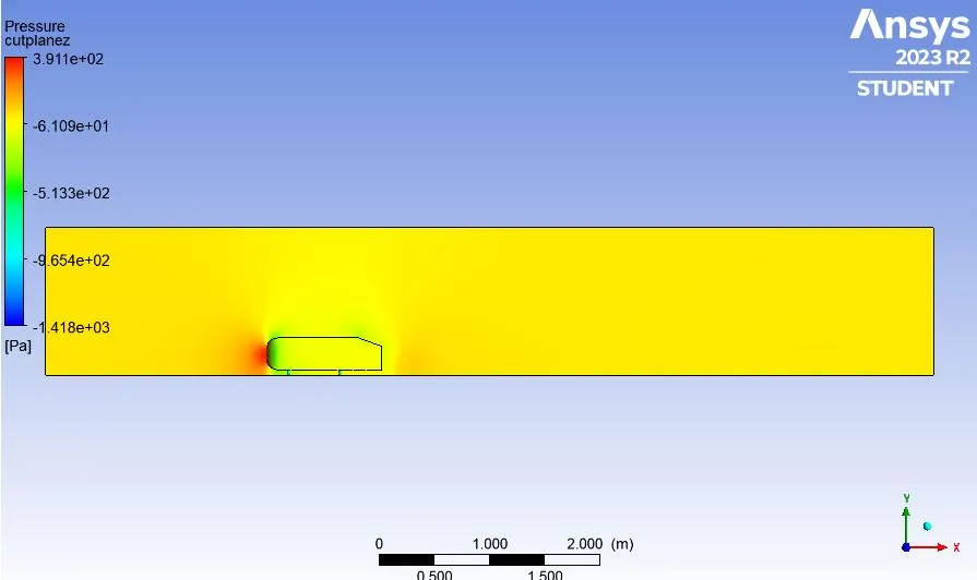
Pressure contour
|
Drag-coefficient |
0.417 |
|
Lift-coefficient |
0.274 |
It can be inferred from the following figure that the results of the base simulation are distorted and do not capture the turbulent flow behind the body perfectly. This simulation captures the wake length, high velocity, low-velocity areas which can be used to further refine the mesh value around the Ahmed body and add a local refinement around.
Case-2 (a): External flow simulation over Ahmed body with finer mesh in a double enclosure.
Turbulence model: k−ωSST
First refinement
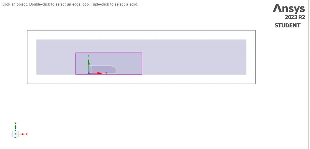
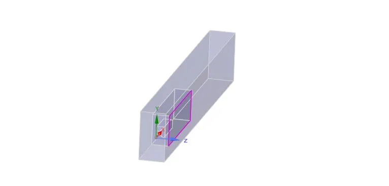
A region of local refinement is added to the Ahmed body and then the body is splitted into two equal halves because of the symmetry as shown below. Doing this will help us to reduce the number of mesh elemnets and computational costs as well.
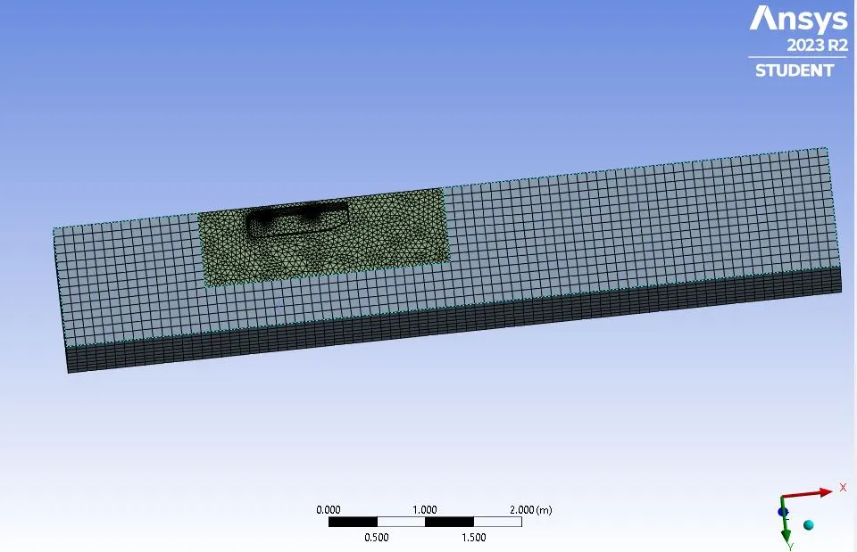
Mesh:
Element size for the first enclosure: 100mm or 0.10m
Maximum size for the first enclosure: 100mm or 0.10m
Element size for the second enclosure: 50mm
Element size of pillars of Ahmed body: 5mm
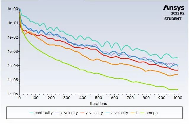
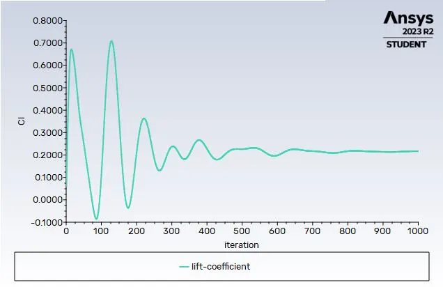
The following plots are captured as shown below:
Residuals
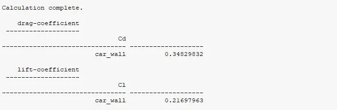
Coefficient of Drag
Coefficient of lift
Velocity Vector contour
Velocity Vector contour(Zoomed)
Pressure contour
|
Drag-coefficient |
0.3482 |
|
Lift-coefficient |
0.2169 |
Case-2 (b): External flow simulation over Ahmed body with second refinment of mesh in a double enclosure.
Turbulence model: k−ωSST
Second refinement
Mesh:
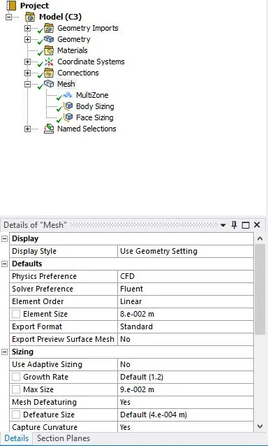
Element size for the first enclosure: 80mm or 0.08m
Maximum size for the first enclosure: 80mm or 0.08m
Element size for the second enclosure: 40mm
Element size of pillars of Ahmed body: 5mm
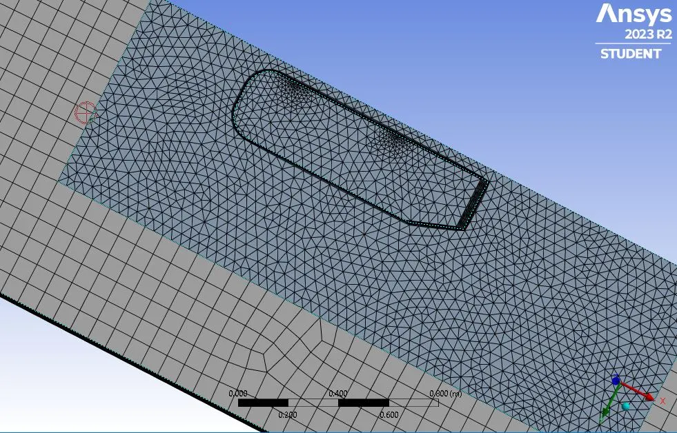
Multi zones, Body Sizing and Face sizings are done in a simillar manner as above as shown in the figure below:
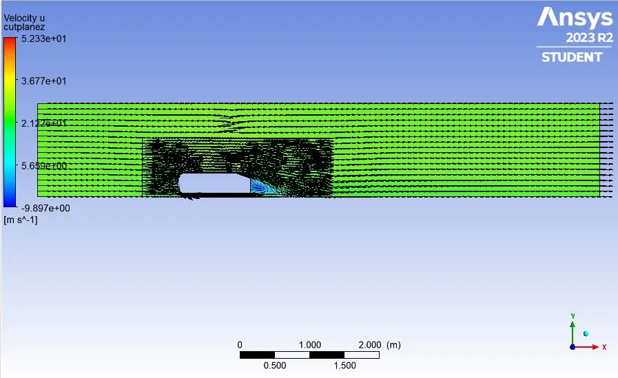
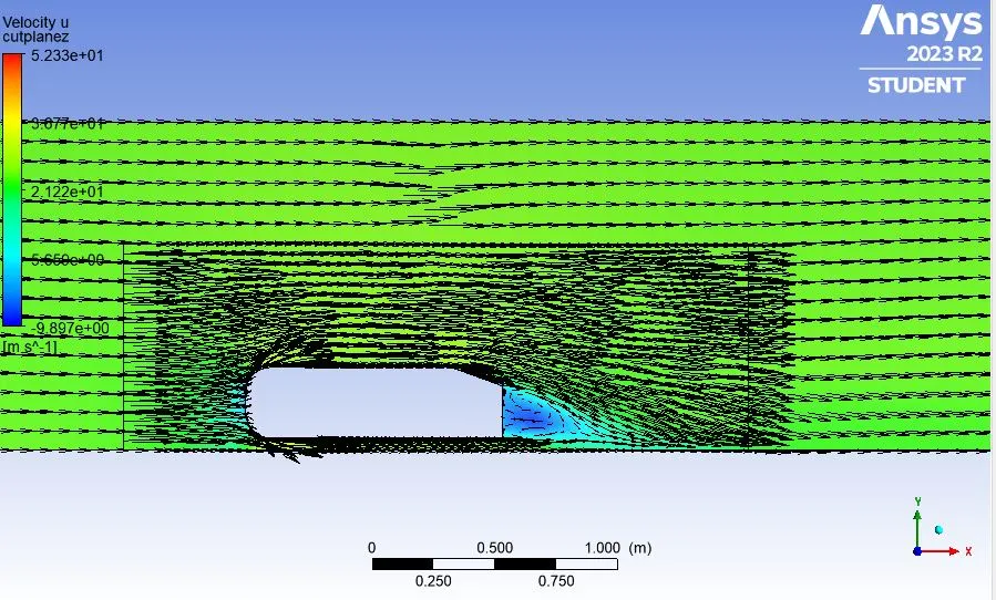
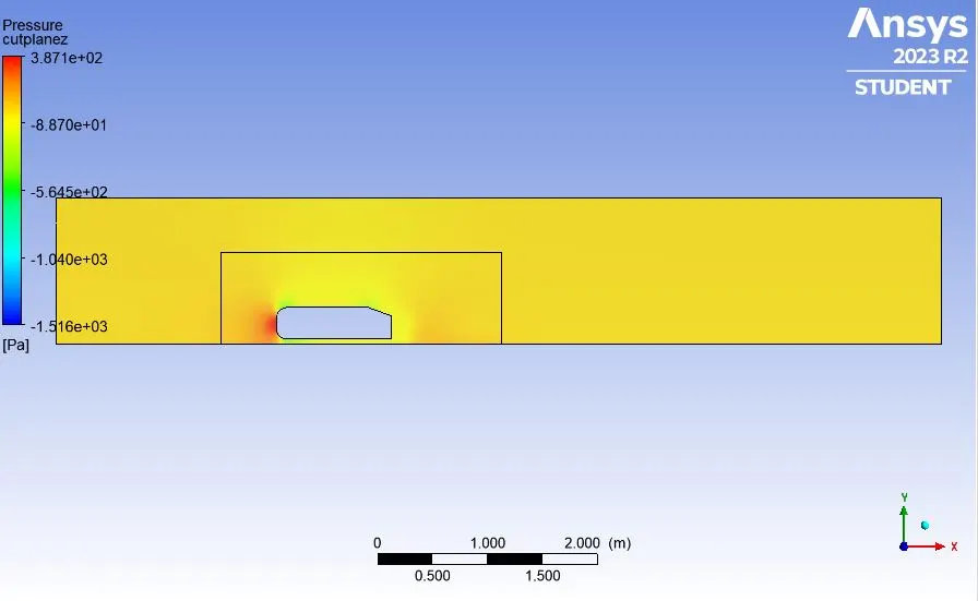
The following plots are captured as shown below:
Residuals
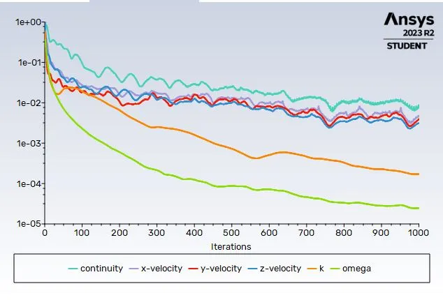
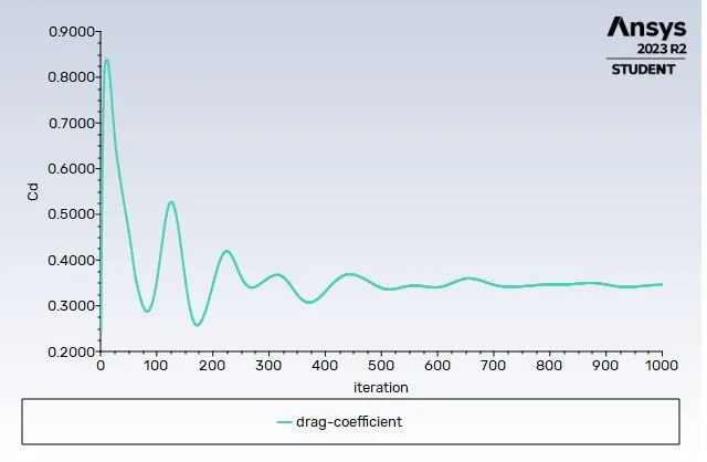
Coefficient of Drag
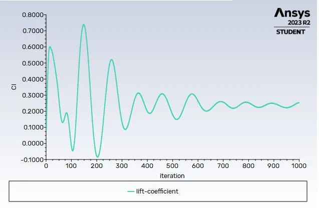
Coefficient of lift
Velocity Vector contour
Velocity Vector contour(Zoomed)
Pressure contour
|
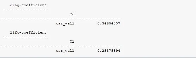
Drag-coefficient |
0.346 |
|
Lift-coefficient |
0.253 |
The summary of all the cases is shown in the table below
| Case | Turbulence Model | Number of cells | Coefficient of drag | Coefficient of lift |
| Base line simulation (Single enclosure with full body without splitting) | K eosilon | 84920 | 0.417 | 0.274 |
| First Refinement of mesh (Double enclosure with splitted body) | K-omega SST | 98695 | 0.349 | 0.217 |
| Second Refinement of mesh (Double enclosure with splitted body) | K-omega SST | 159786 | 0.346 | 0.253 |
It can be inferred that the imitation of the experimental result is obtained during the second refinement. Thus the grid independence test saves a lot of computational time and convergence can be achieved by using smaller cell sizes for calculation.
Conclusions:
• The grid independence test is presumably carried out to determine the lower cell size required for convergence.
• In addition to mesh refinement, convergence is influenced by the Y+ value and inflation layer. It is recommended to choose k SST as the turbulence value because it accurately calculates values close to walls.
• As the setup is improved, the lift coefficient declines.
• Y+ is crucial in figuring out how much drag there is.
• The absence of flow in the wake region is the main reason of the negative pressure there. The vector plot close to the wake zone shows that this can also be due to other variables including separation and recirculation.
• The point of separation is located at the rear of the vehicle; beyond this point, the flow is seen to recirculate and become attached to the boundary layer.
Reference:
Case set-up and Results
https://drive.google.com/file/d/18Qta80ENjBWApSIIK2apkdzHgQ-DJYtk/view?usp=sharing