Challenge on Combustion
Problem Statement:
1. Perform the simulation analysis using methane-air fuel mixture and plot the variation of mass fraction of different species using line probes at different locations of the combustion chamber.
2. Study the effect of adding water to the methane-air mixture and plot the same and discuss the results.
Introduction:
Combustion:
Combustion is a chemical process in which a substance reacts rapidly with oxygen and gives off heat. The original substance is called fuel and the source of oxygen is called oxidizer. The fuel can be solid, liquid, or gas although for airplane propulsion the fuel is usually a liquid. The oxidizer likewise could be solid, liquid, or gas but is usually a gas for airplanes. For model rockets, solid fuel and oxidizer are used.
During combustion, new chemical substances are created from the fuel and the oxidizer. These substances are called exhaust. Most of the exhaust comes from chemical combinations of fuel and oxygen. When a hydrogen-carbon based fuel burn the exhaust includes water and carbon dioxide. But the exhaust can also include chemical combinations from eh oxidizer alone. If the gasoline is burned in air, which contains 21% oxygen and 78% nitrogen, the exhaust can also include nitrous oxides (NOX, nitrogen+oxygen). The temperature of the exhaust is high because of the heat that is transferred to the exhaust during combustion. Because of the high temperatures, exhaust usually occurs as a gas but there can be liquid or solid exhaust products as well such as soot. Soot is a form of solid exhaust that occurs in some combustion processes.
During the combustion process. as the fuel and oxidizer are turned into exhaust products, heat is generated. Source of heat is necessary to start combustion. Gasoline and air are both present in the fuel tank but combustion does not occur because there is no source of heat. Since heat is both required to start combustion and is itself a product of combustion. Source of heat is required only to start the combustion and the combustion reaction keeps things going with the heat generated during the combustion reaction.
Types of combustion simulation:
a) Non-premixed combustion (Direct injection, Late injection)
b) Premixed Combustion (Carburetor)
c) Partially premixed.
Non-premixed combustion:
In non-premixed combustion, fuel and oxidizer enter the reaction zone in distinct streams. This is in contrast to premixed systems, in which reactants are mixed at the molecular level before burning. Examples of non-premixed combustion include pulverized coal furnaces, diesel internal-combustion engines, and pool fires.
Direct injection is used in heavy-duty vehicles. Similar to diesel engines, high thermal efficiency and power density are maintained in such direct injection natural gas engines. In such engines, natural gas is injected directly into the combustion chamber. Then the gas mixes with the high-pressure air in the combustion chamber and combustion occurs. Due to the non-premixed nature of the combustion occurring in such engines, a non-premixed combustion model of ANSYS FLUENT can be used to simulate the combustion process.
Premixed Combustion:
In premixed combustion, fuel and oxidizer are mixed at the molecular level prior to ignition. Combustion occurs as a flame front propagating into the unburnt reactants. Examples of premixed combustion include aspirated internal combustion engines, lean-premixed gas turbine combustors, and gas-leak explosions.
Premixed combustion is difficult to model that non-premixed combustion. The reason for this is that premixed combustion usually occurs as a thin, propagating flame that is stretched and contorted by turbulence. For subsonic flows, the overall rate of propagation of the flame is determined by both laminar and turbulent eddies. The laminar flame speed is determined by the rate that species and heat diffuse upstream into the reactants and burn. To capture the laminar flame speed, the internal flame structure would need to be resolved, as well as the detailed chemical kinetics and molecular diffusion processes. Since practical laminar flame thicknesses are of the order of millimeters or smaller, resolution requirements are usually unaffordable.
The effect of turbulence is to wrinkle and stretch the propagating laminar flame sheet, increasing the sheet area and in turn the effective flame speed. The large turbulent eddies tend to wrinkle and corrugated the flame sheet while the small turbulent eddies if they are smaller than the laminar flame thickness, may penetrate the flame sheet and modify the laminar flame structure.
Partially premixed Combustion:
Partially premixed combustion systems are premixed flames with non-uniform fuel-oxidizer mixtures. Such flames include premixed jets, discharging into a quiescent atmosphere, lean-premixed combustors with diffusion pilot flame and cooling air jets, and imperfectly mixed inlets.
The partially premixed model in FLUENT is a simple combination of the non-premixed model and the premixed model. The premixed reaction progress variable determines the position of the flame front. Behind the flame front, the mixture is burnt and the equilibrium or laminar flamelet mixture fraction solution is used. Ahead of the flame front the species mass fractions, temperature, and density are calculated from the mixed but unburnt mixture fraction. Within the fame, a linear combination for the unburnt and burnt mixtures is used.
b) Based on phase:
1. Fluid phase:- In this model, the fuel is in the liquid phase and combustion reactions are happening at the volume of the chamber.
2. Wall:- In this model, the combustion reactions are done at the surface of the combustion chamber.
3. Particles:- In this model, the reactions are being performed at the surface of the particles.
4. Porous regions:- In this model, the reactions are being performed in the porous regions.
Combustion Source Calculation:
Finite Rate Chemistry:
This model derives ODE for all species and solves them. It results in accurate solutions but the computational time required to solve the ODE is increased as the number of species involved is more.
Mixing based model:
Eddy dissipation model:
In this model, the combustion takes place when there is a presence of turbulence, hence it does not require any heat source to initiate the combustion reaction. This model is valid for non-premixed fuel mixture.
Finite rate Eddy dissipation model:
It is the combination of both finite rate chemistry and the eddy dissipation model. In this model, the kinetic rate is calculated in addition to the reaction rate calculated from the eddy dissipation model.
Then the slowest reaction is chosen.
1. If turbulence is low, the species mixing rate is low, this limits the reaction rate.
2. If turbulence is high, the kinetic rate is low, this limits the reaction rate.
Geometry:

Inlet side of the model:
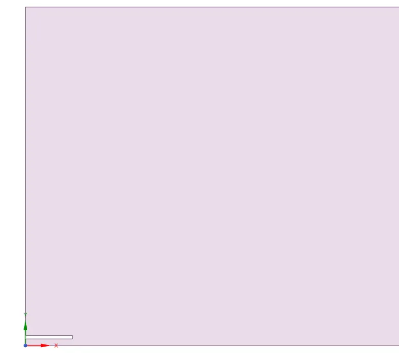
The rectangular gap at the bottom of the model act as a compressor for the fuel.
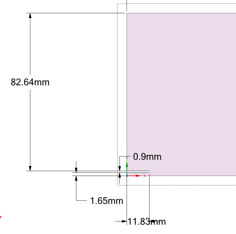
Dimensions of the model:

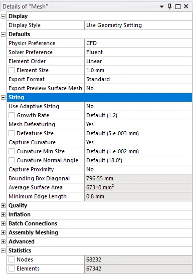
Mesh parameters:
Mesh

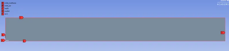
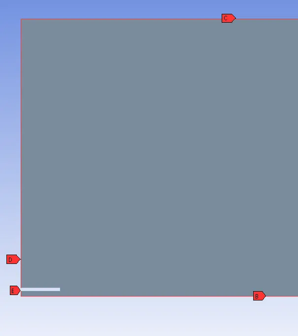
Named Selection:
Setting up Physics:
1. Standard K-epsilon turbulence model with standard wall function is chosen as we are interested in the analysis of the combustion reaction than the wall phenomenons.
2. Species model is chosen as species transport as there is a separate inlet for air and fuel. The fuel chosen is methane-air. The volumetric combustion phase of the model is chosen. The combustion
3. Chemical interaction chosen is the Eddy dissipation model. This model is chosen because it requires less computational time when compared to other models and also requires fewer hardware requirements. In this model, the start time of combustion is calculated based on the turbulence kinetic energy 'k' and epsilon. Here the heat source of the combustion is the turbulence of the fuel mixture.
4. Axis symmetric model is chosen as the bottom of the model axis boundary condition is applied.
5. Boundary condition:
At inlet for fuel:
Material: Methane
Mole fraction:
`CH_4` = 1.
`O_2` = 0.
`H_2O` = 0.
`CO_2` = 0.
At inlet for Air:
Mole fraction:
`CH_4` = 0.
`O_2` = 0.21
`H_2O` = 0.
`CO_2` = 0.
Top boundary: wall
Bottom boundary: Axis.
The base chemical reaction of methane with air is as follows:
`CH_4 + ar(O_2+3.76N_2)-> aCO_2+b H_2O+cN_2`
where a,b and c are no. of moles of the products.
`(O_2+3.76N_2)` - air
`CH_4`- methane fuel.
The above equation is solved for stoichiometry balance.
we get,
a =1, b=2, c=7.52, ar=2.
From the coefficients,
2 moles of `O_2` and 7.52 moles of `N_2` is required for combustion of 1 mole of `CH_4`
Total moles = 9.52
Calculation of Mole Fraction:
Mole fraction of `O_2` = `2/9.52 =0.21`
Mole fraction of `N_2` = `7.52/9.52 =0.79`
6. Parametric study is performed to observe the Nox and soot formation by varying the mass fraction of `H_2O` in the inlet fuel.
Location of line probes in the combustion chamber.

Results:
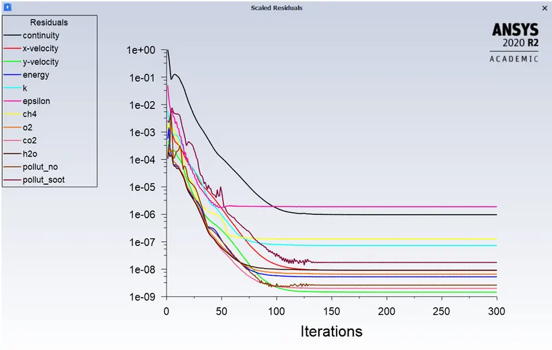
Residuals:
`CH_4` contour plot:
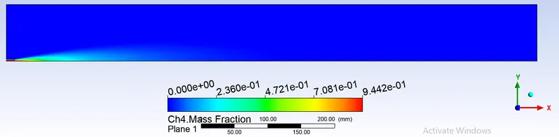
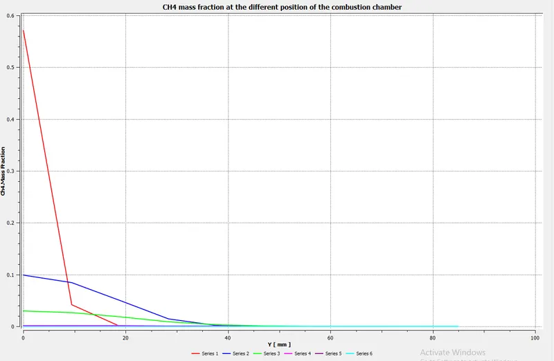
The mass fraction of `CH_4` describes the fuel not burnt at the injection region where the fluid is still flowing and penetrates towards the combustion chamber with a velocity of 80m/s and 0 for the rest of the domain which indicates complete combustion has taken place.
`O_2` contour plot:
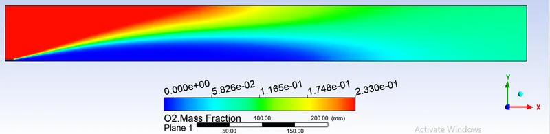
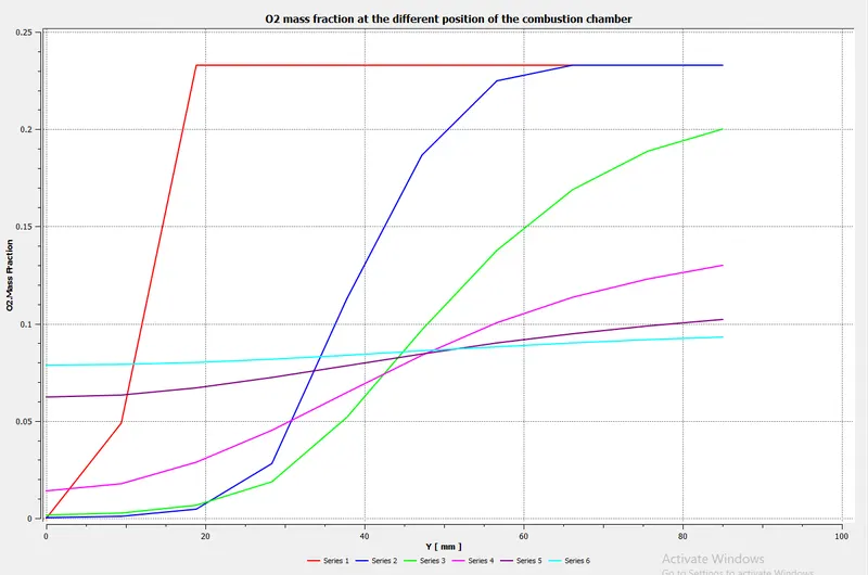
Mass fraction of `O_2` describes that there is an untouched part of the air in the domain which indicates that those places where combustion has not taken place and places, where the mass fraction of `O_2` is zero, indicating there is complete combustion.
`N_2` contour plot:
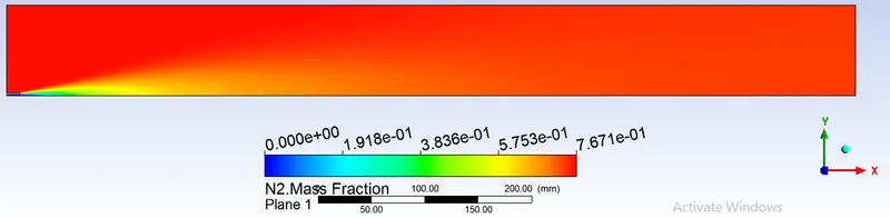
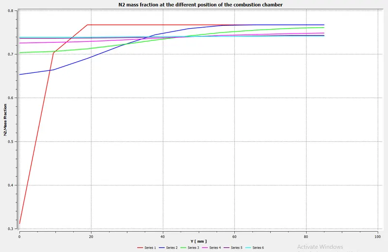
From the above contour plot, it is observed that the `N_2` concentration is higher all over the combustion chamber because nitrogen forms a large portion of the atmosphere, and also it less reactive with the other species
`H_2O` contour plot:
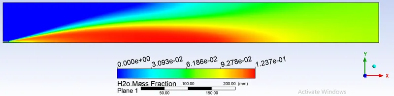
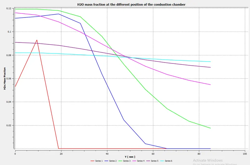
Mass fraction of the `H_2O` contour plot describes that the water concentration is decreased as the combustion takes place.
`CO_2` contour plot:
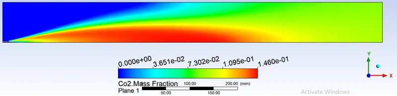
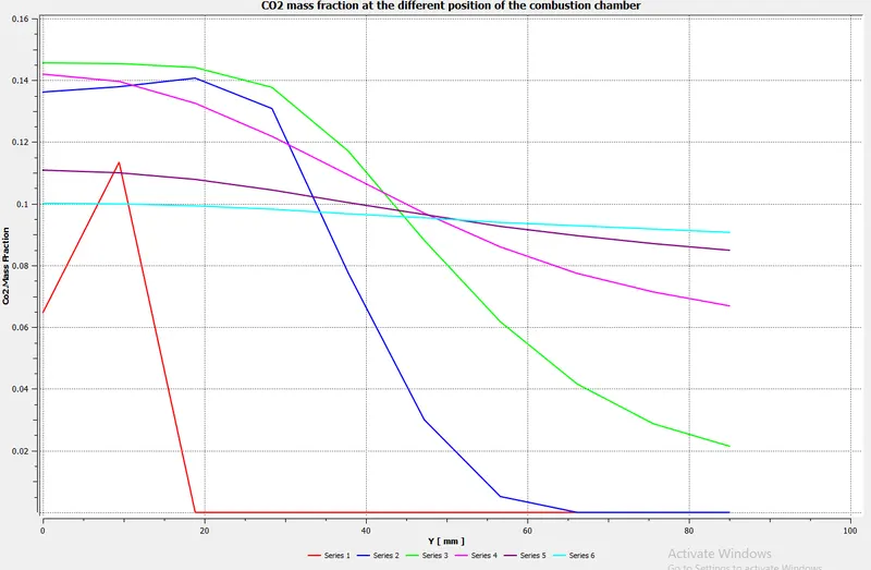
Mass fraction of `CO_2` contour plot describes that the combustion zone that has taken place and that its concentration increases as the combustion proceeds.
NOx contour plot:
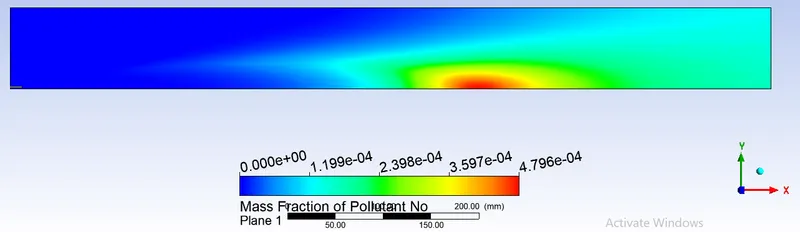
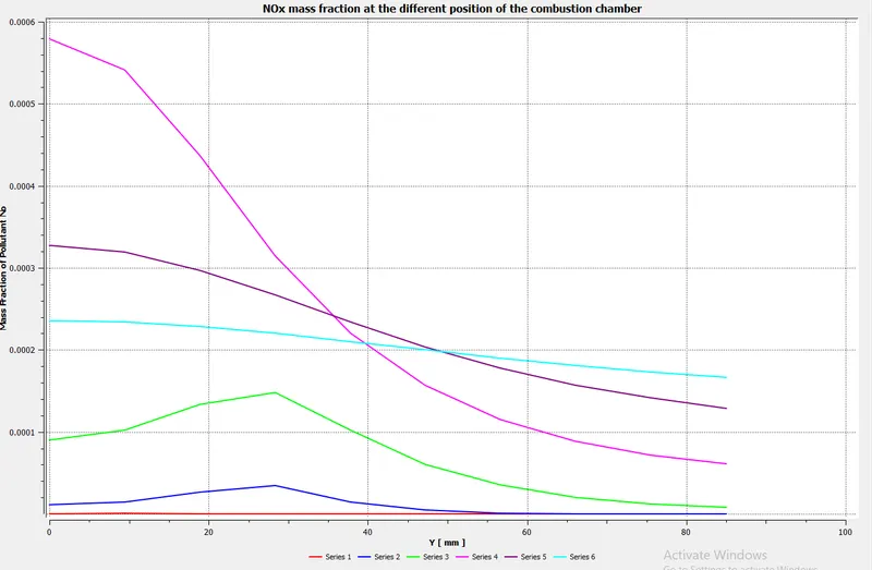
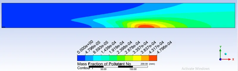
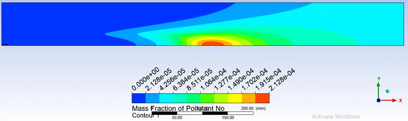
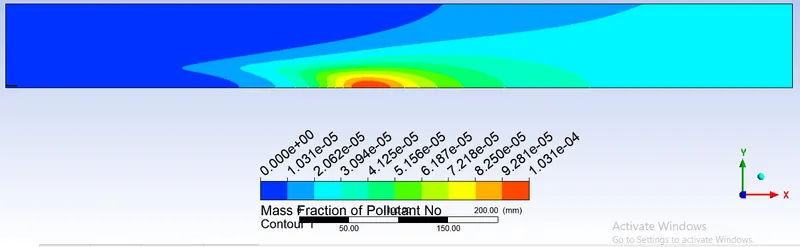
From the above contour plot, the NOx pollutant formation is high at a distance of 500mm from the inlet of the combustion chamber as the formation of NOx is due to the reaction between nitrogen and oxygen at a high temperature. Due to the combustion process, the temperature is high at the midsection of the combustion chamber which leads to the formation of NOx pollutants.
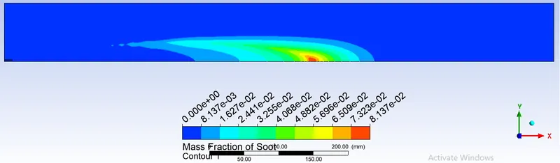
Soot contour plot:
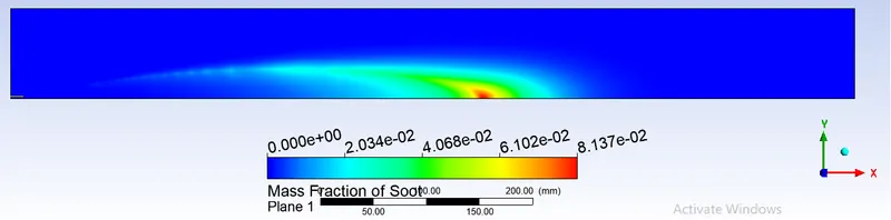
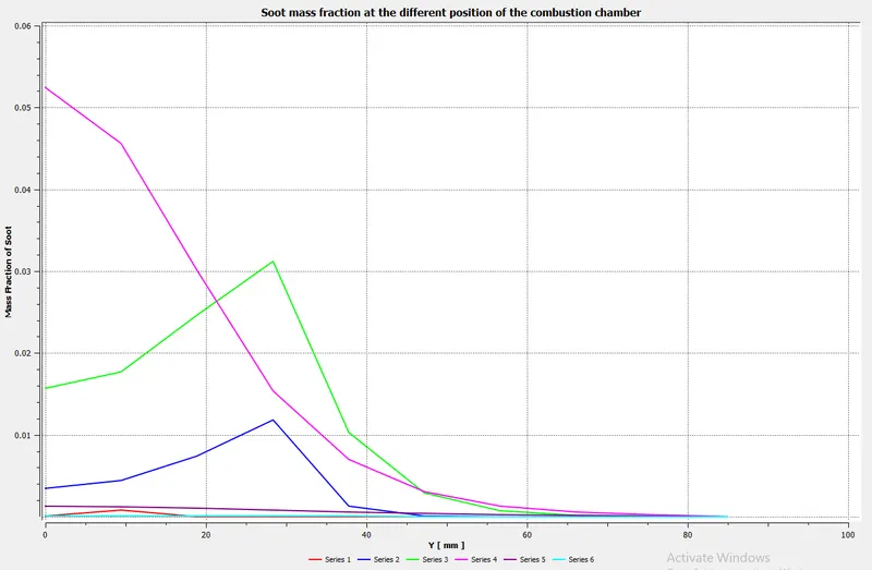
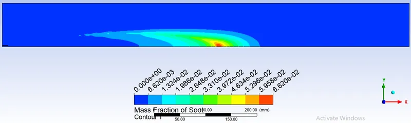
From the above contour plot, the mass concentration of the soot is increasing along the length of the combustion chamber and is maximum at the midsection of the chamber because as the combustion proceeds the amount of percentage of `O_2` available for combustion decreases and at the mid-section of the combustion chamber, the percentage of oxygen is least and hence there is the high mass fraction of soot at the midsection.
Temperature Plot:
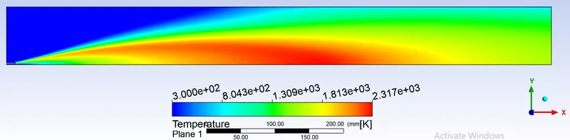
From the temperature contour plot, the temperature increases as the combustion proceeds and is maximum at the midsection of the combustion chamber.
The purpose of supplying engines with water.
Minimizing temperature peaks during the combustion process in diesel engines, hence NOx concentration in the exhaust gas can be done by means of supplying water into the cylinder.
The emulsion supplied into the cylinder causes the increase of self-ignition delay which affects the flammable mixture becoming more homogeneous in the whole volume of the combustion chamber. The increased self-ignition delay extends the time necessary to spread the injected fuel which results in fewer zones with not enough oxygen. That decreases the intensity of soot and CO formation. Emulsifying the mixture reduces local zones with temperature peaks which leads to decreasing nitrogen activity and NOx concentration.
Water supplied into the combustion chamber, apart from lowering the combustion temperature also decreases the concentration of atomic oxygen by reaction
`H_2O -> OH+H`
`H_2O+O->OH+OH`
`H_2+O-> H+OH`
`H+O_2-> OH+O`
which influences the reaction speed:
`O+N_2 harr NO+N`
`O+N_2+OH harr N_2O+OH`
OH formed this way is more difficult to interact with atomic N which lowers the amount of NO.
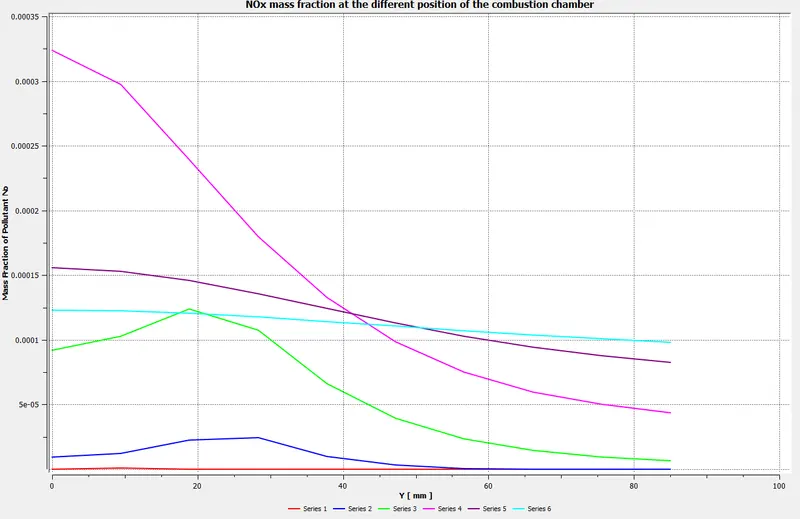
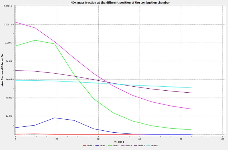
Parametric study is performed for different moles of water in the methane-air mixture:

| Mass fraction of water | Mass Fraction of Methane | Mass fraction of Pollutant NOx | Mass Fraction of Soot Formation | Mass Fraction of `CH_4` | Mass Fraction of `CO_2` | Mass Fraction of `H_2O` | Mass Fraction of `O_2` | Mass Fraction of `N_2` | Velocity in m/s | Temperature in K |
| 0 | 1 | 0.00019131 | 2.8723E-05 | 1.0712E-06 | 0.094201 | 0.077122 | 0.087936 | 0.74074 | 2.3743 | 1325.6 |
| 0.05 | 0.95 | 0.0001445 | 9.2326E-06 | 4.5118E-07 | 0.089487 | 0.075191 | 0.094741 | 0.74058 | 2.2759 | 1270.4 |
| 0.1 | 0.9 | 0.00010732 | 2.9636E-06 | 2.0036E-07 | 0.084769 | 0.073256 | 0.10155 | 0.74042 | 2.182 | 1217.8 |
| 0.2 | 0.8 | 5.3861E-05 | 2.9302E-07 | 3.4255E-08 | 0.075336 | 0.069387 | 0.11517 | 0.7401 | 1.9937 | 1112.4 |
| 0.3 | 0.7 | 2.3205E-05 | 2.1579E-08 | 4.6475E-09 | 0.065906 | 0.065519 | 0.12879 | 0.73978 | 1.8047 | 1006.6 |
Contour plots for NOx pollutant for different percentage of mass fraction of water in the methane-air mixture:
Mass fraction of water 0.05 & Mass fraction of methane 0.95
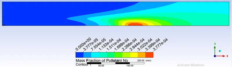
Mass fraction of water 0.1 & Mass fraction of methane 0.9
Mass fraction of water 0.2 & Mass fraction of methane 0.8
Mass fraction of water 0.3 & Mass fraction of methane 0.7
Contour plots for Soot formation for different percentage of mass fraction of water in the methane-air mixture:
Mass fraction of water 0.05 & Mass fraction of methane 0.95
Mass fraction of water 0.1 & Mass fraction of methane 0.9
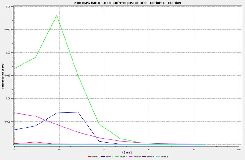
Mass fraction of water 0.2 & Mass fraction of methane 0.8
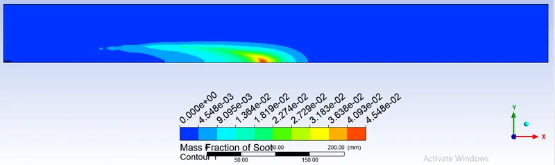
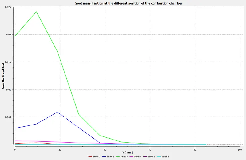
Mass fraction of water 0.3 & Mass fraction of methane 0.7

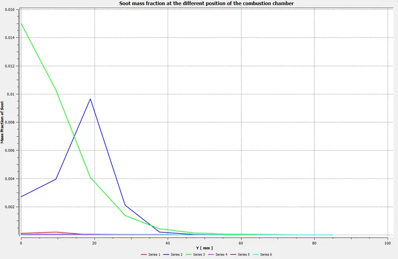
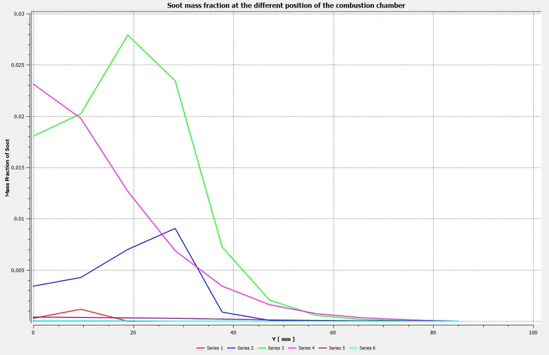
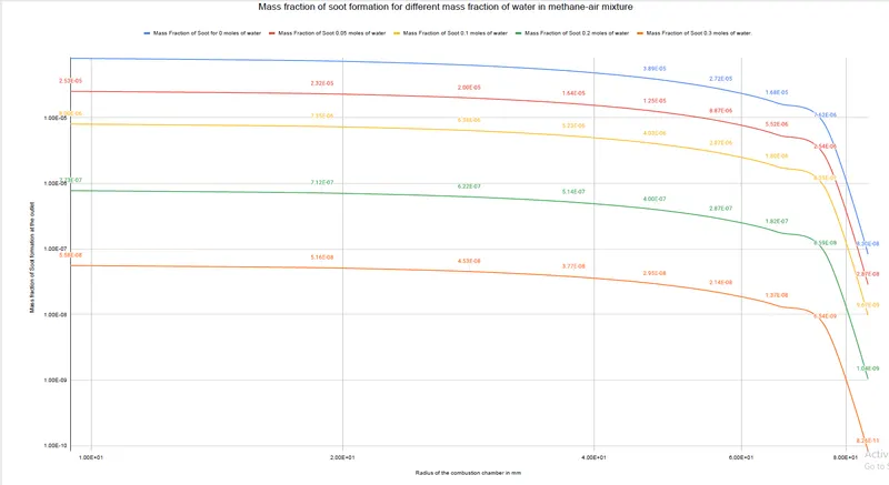
Line plots comparing the Mass fraction of Soot for different percentages of water in the inlet fuel.
Drive link attached for a clear view of the above chart.
https://drive.google.com/file/d/19ztn9K4bqxj2OyUU0Cf-ctPGmkLDRGp-/view?usp=sharing
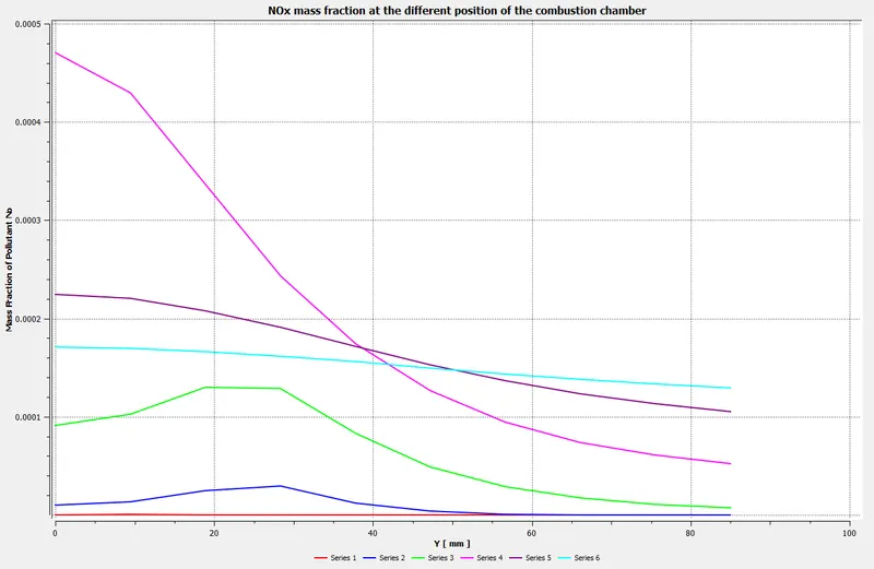
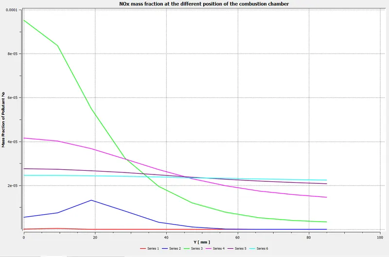
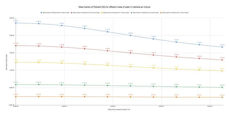
Line plots comparing the Mass fraction of NOx pollutant for different percentages of water in the inlet fuel.
Drive link attached for a clear view of the above chart.
https://drive.google.com/file/d/16g3gRpLvwPDt-jwwozTDeMFLRcc5H106/view?usp=sharing
The above line plots were plotted using the data points obtained at the outlet of the combustion chamber since the NOx pollutant and Soot formation are measured based on the quantity of the NOx and soot emitted for burning a particular quantity of fuel at the outlet of the combustion chamber
Inference:
From the above plots, it is observed that the NOx and soot formation is reduced with an increase in the mole fraction of water in the methane-air mixture. With the addition of water in the fuel mixture, the temperature is reduced which in turn delays the combustion to takes place which leads to an efficient mixture of fuel and air. With the proper mixture of fuel and air complete combustion takes place because of which nitrogen oxides formation is reduced as there is no oxygen left to react with nitrogen to form nitrogen oxides.
Soot is formed as a result of the burning of fuel in presence of less oxygen at low temperatures. As complete combustion takes place due to efficient mixing of the fuel and air there is very less amount of fuel and oxygen present after combustion as a result the soot formation is reduced.
Conclusion:
1. With the increase in the Mass fraction of water in the fuel-air mixture NOx pollutant is reduced.
2. With the increase in the Mass fraction of water in the fuel-air mixture Soot formation is reduced.
3. With the increase in the Mass fraction of water in the fuel-air efficient mixture of fuel-air is achieved.
4. With the increase in the Mass fraction of water in the fuel-air mixture temperature of the exhaust gases is reduced.
5. With the increase in the Mass fraction of water in the fuel-air mixture velocity of the exhaust gas is reduced.