Challenge on Combustion
Aim: Perform a combustion simulation on the combustor model and plot the variation of the mass fraction of the different species in the simulation using line probes at different locations of the combustor.
Objective:
(1). Perform a combustion simulation on the combustor model and plot the variation of the mass fraction of the different species’ in the simulation using line probes at different locations of the combustor. Here, you need to plot for CO2, H2O, CH4, N2, O2, NOx emissions & Soot formation.
(2). As you must have observed from the above simulation, the Nox and soot are getting formed at the outlet of the combustor. Such formation has harmful effects on the environment and humans. The stringent government norms also demand the least formation of Nox and soot and to satisfy those requirements, you need to check the effect of adding the water to the fuel. In this part, you need to add the water content in the fuel from 5% to 30% by mole and observe the effect of it on the results. It is necessary to provide line plots and contours to prove your claim.
Theory:
Combustion:
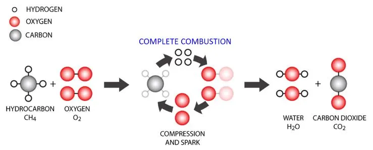
Combustion is the scientific word for burning. In a combustion reaction, a substance reacts with oxygen from the air and transfers energy to the surroundings as light and heat. The products of a combustion reaction are called oxides.
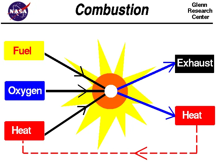

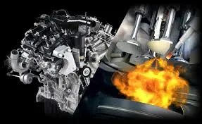
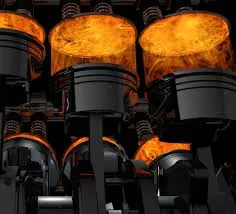
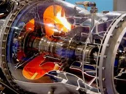
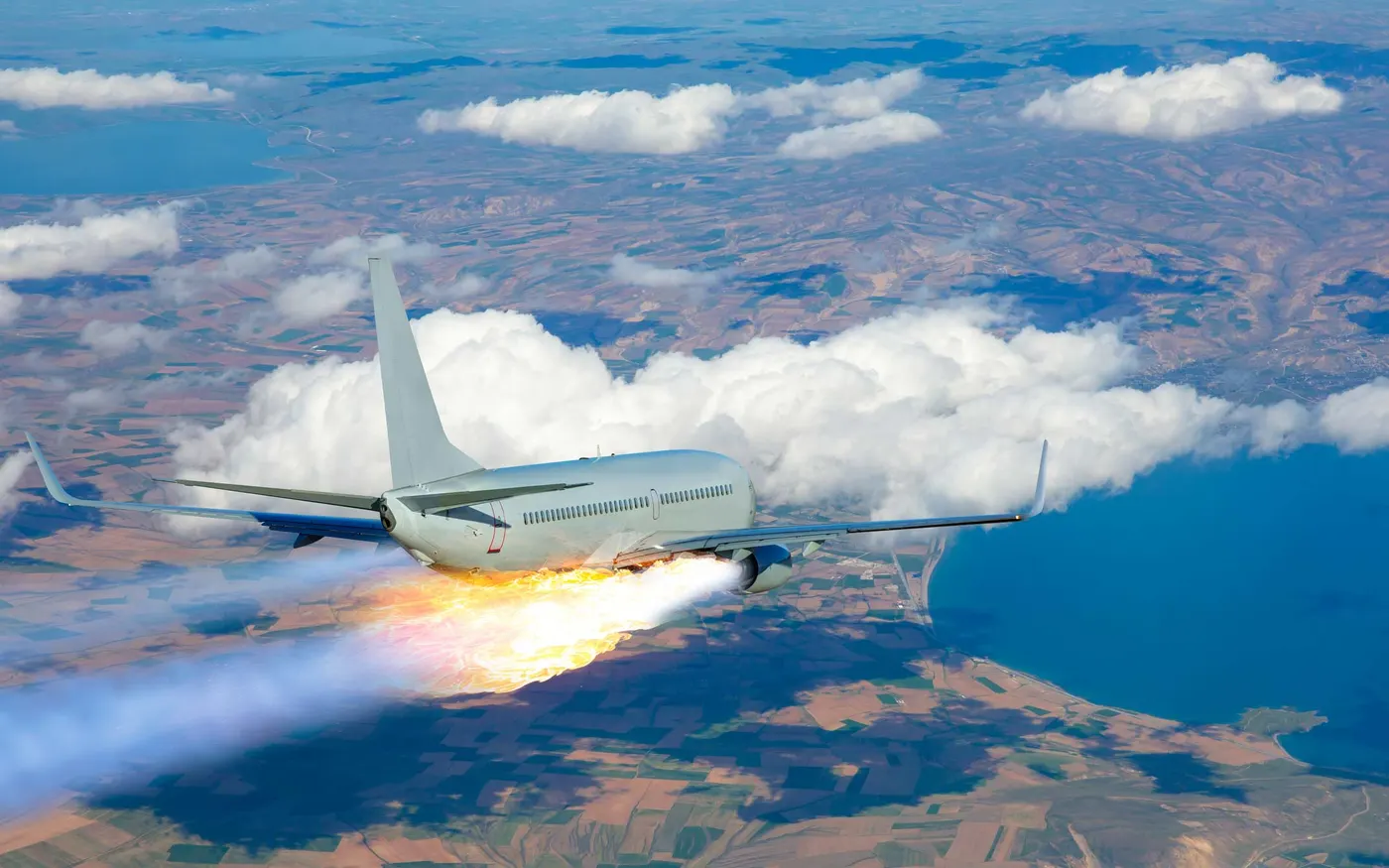
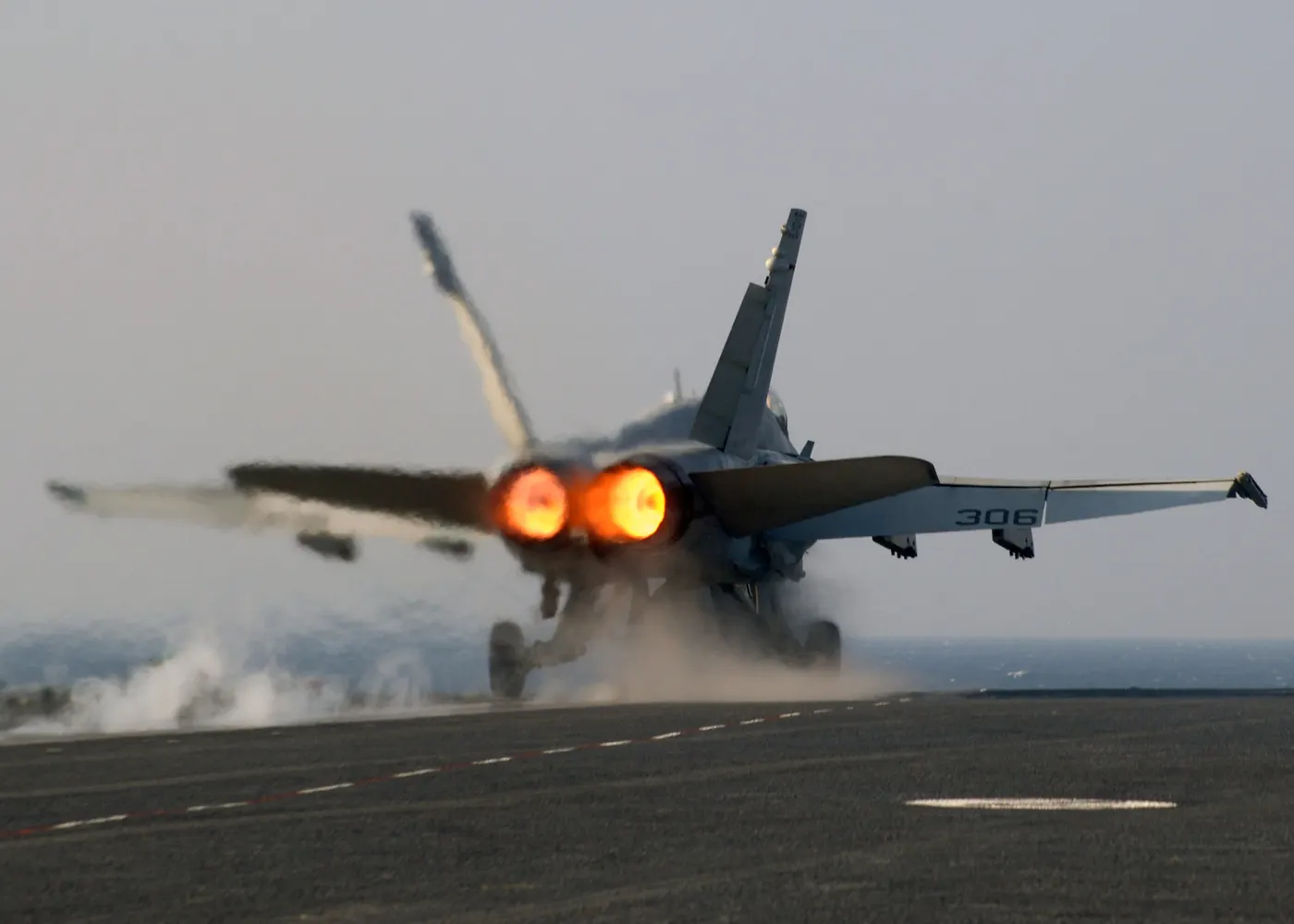
To move an airplane or a model rocket through the air, we must use a propulsion system to generate thrust. Different types of aircraft use different types of propulsion devices, but all aircraft rely on some type of engine to generate power. Rocket engines, internal combustion, or piston engines, and jet engines all depend on the burning of fuel to produce power. Burning fuel is called combustion.
Types of combustion simulation in Fluent:-
Combustion modeling:
A large percent of the worldwide energy conversion processes are based on combustion. Software from ANSYS offers a wide range of user-friendly models to simulate the interaction between flow, turbulent mixing, heat release, and chemical reaction.
Non-premixed combustion:
With the non-premixed (or diffusion flame) model, the turbulence chemistry interaction is described using an assumed shape of the probability density function. The thermodynamic state of the fluid, related to the mixture fraction, and the chemistry is calculated either from equilibrium or by using a tabulated steady flamelet approach. The non-premixed model offers a robust and fast solution for any turbulent reacting flow that is at or near chemical equilibrium. This model is often used for gas turbines, process furnace, and ic engine applications.
Premixed and Partially premixed combustion:
For a premixed flame, an additional transport equation is solved for the reaction progress variable, flame surface density, or distance to the flame front. The solution of this variable predicts the position of the flame front. For closure of the source term, ANSYS offers different proven correlations related to the turbulent burning velocity. These correlations provide the best practical method to predict turbulent premixed flames. In combination with the equilibrium or flamelet model, This approach is applicable to partially premixed or fully premixed combustion.
Turbulent combustion:
Because chemical kinetics are highly nonlinear, turbulence chemistry interactions should be taken into account to accurately predict turbulent reacting flows. Fluid dynamics software from ANSYS offers a wide range of turbulent chemistry interaction models of various complexities suitable for almost every turbulent reacting flow application.
Fast chemistry:
The eddy dissipation model (EDM), in combination with the finite rate chemistry model, allows accurate simulation of heat release and the distribution of the main chemical species for many industrial applications, such as gas turbines, internal combustion engines, furnaces, and thrusters. The EDM can be used for all type of combustions as well as in combination with advanced scale resolving turbulence and multiphase models.
Based on phase models:
1. Fluid phase: When the combustion takes place in fluids.
2. Wall(surface reactions): When the combustion takes place on the wall.
3. Particles(surface reactions): When the combustion takes place on the surface of the particles.
4. Porous region: When the combustion takes place inside the region.
Depending on the region:
1. Wall: Combustion taking place at the walls.
2. Particles: Combustion on the surface of the particle.
3. Porous region: Combustion taking place inside the region.
Limitations:-
1. The underlying theory, assumptions, and limitations of the non-premixed and premixed models apply directly to the partially premixed model. In particular, the single-mixture-fraction approach is limited to two inlet streams, which may be pure fuel, pure oxidizer, or a mixture of fuel and oxidizer. The two-mixture-fraction model extends the number of inlet streams to three but incurs a major computational overhead.
2. The Flamelet Generated Manifold (FGM) model is limited to the C-Equation partially-premixed model.
Simulations:
Geometry:
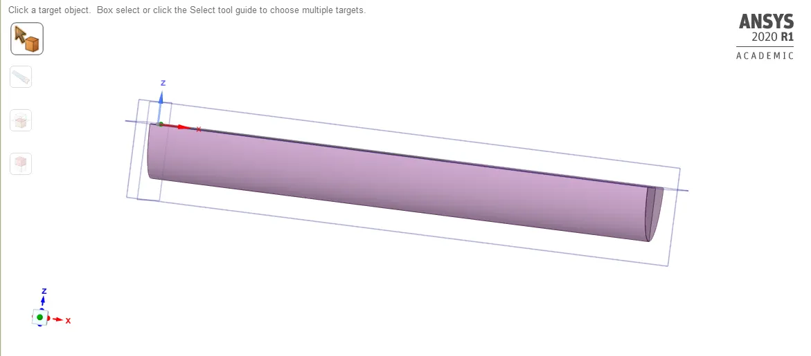
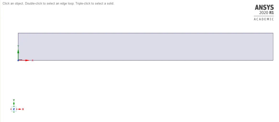
3D model of the combustor is provided for the simulation. In this cylinder, Methan and air are mixed and combusted. The volume of air compared to fuel is very high. And create a plane for it.
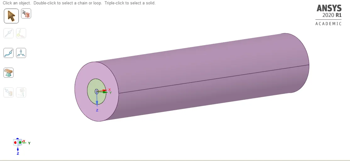
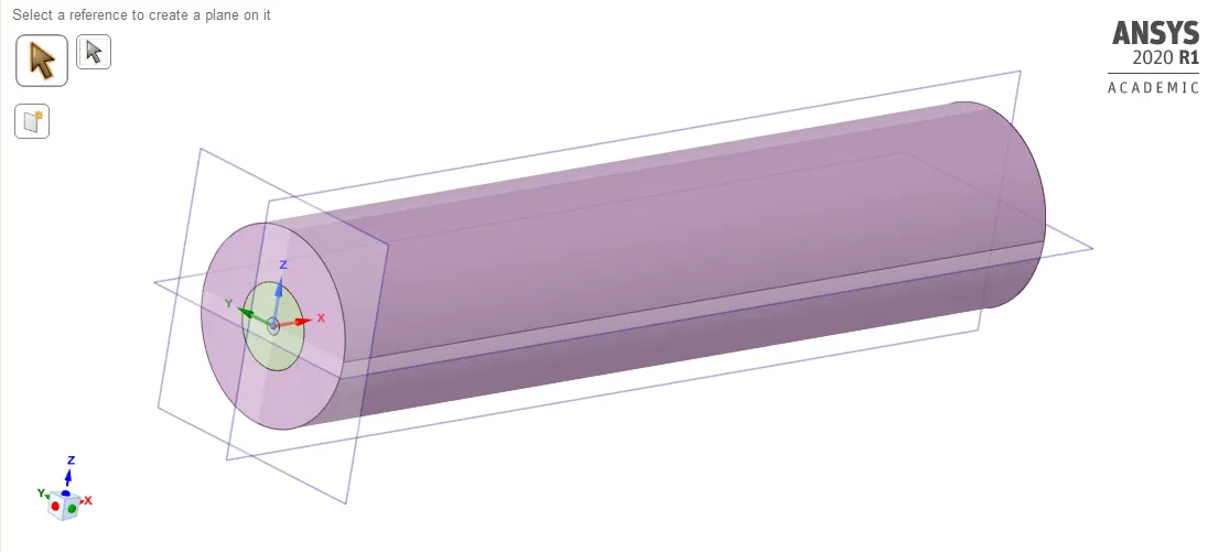
The small gap between the two cylinders is the fuel injection area.
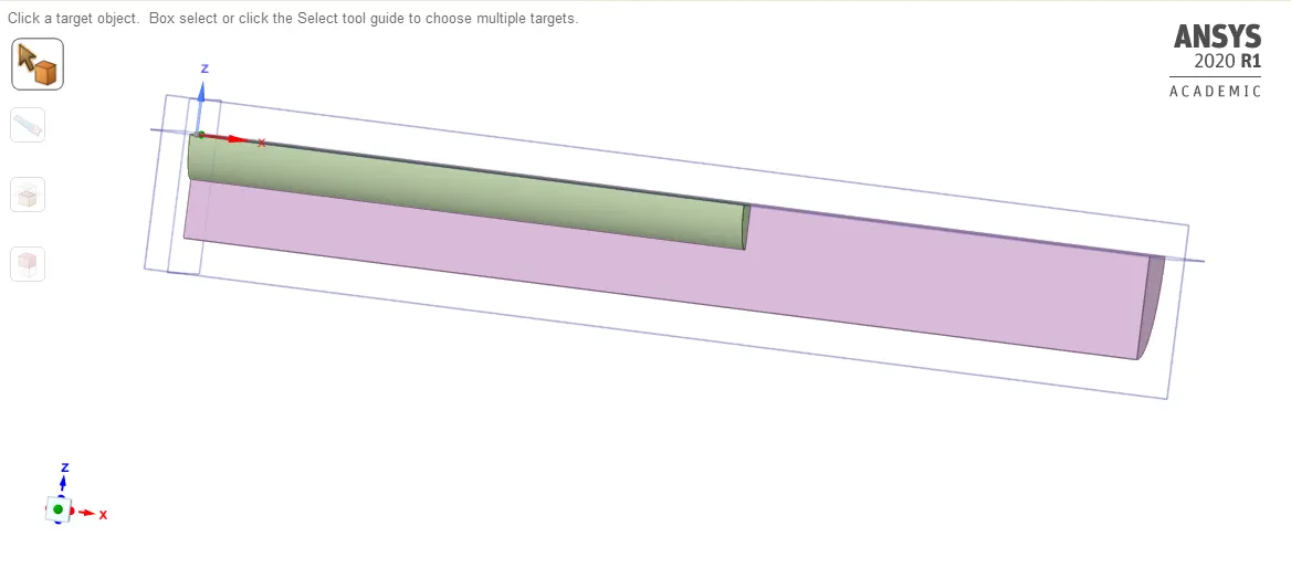
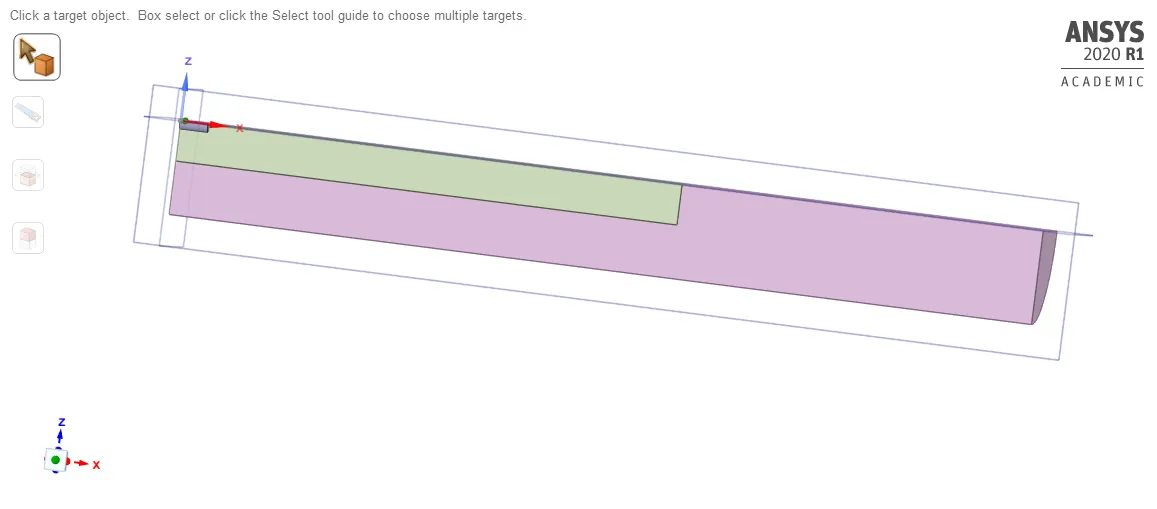
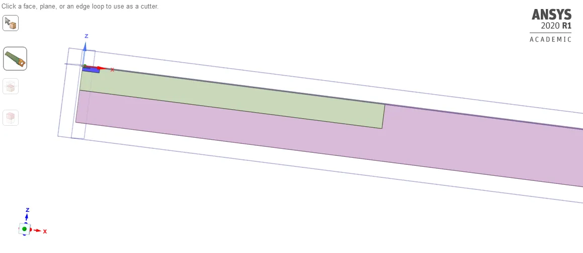
- To reduce the computational effort we convert this 3D geometry into 2D. For this first of all creating the plane XY-plane, then we choose the spilt body option and after that, we select the desired body and then we cut the desired body.
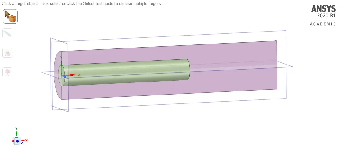
- We follow the same for inner bodies:
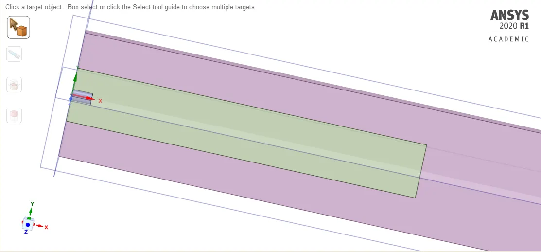
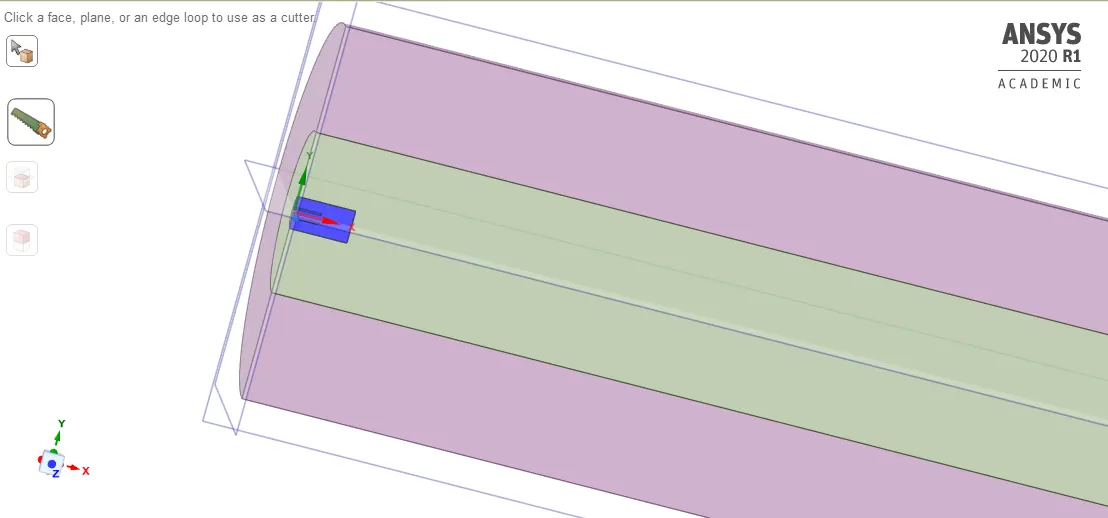
Next, we cut another part of a geometry:
Merge the multiple targets:
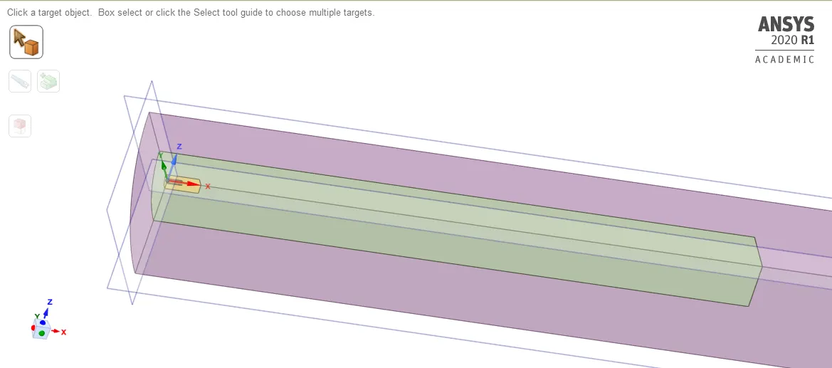
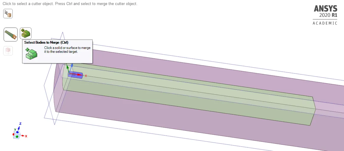
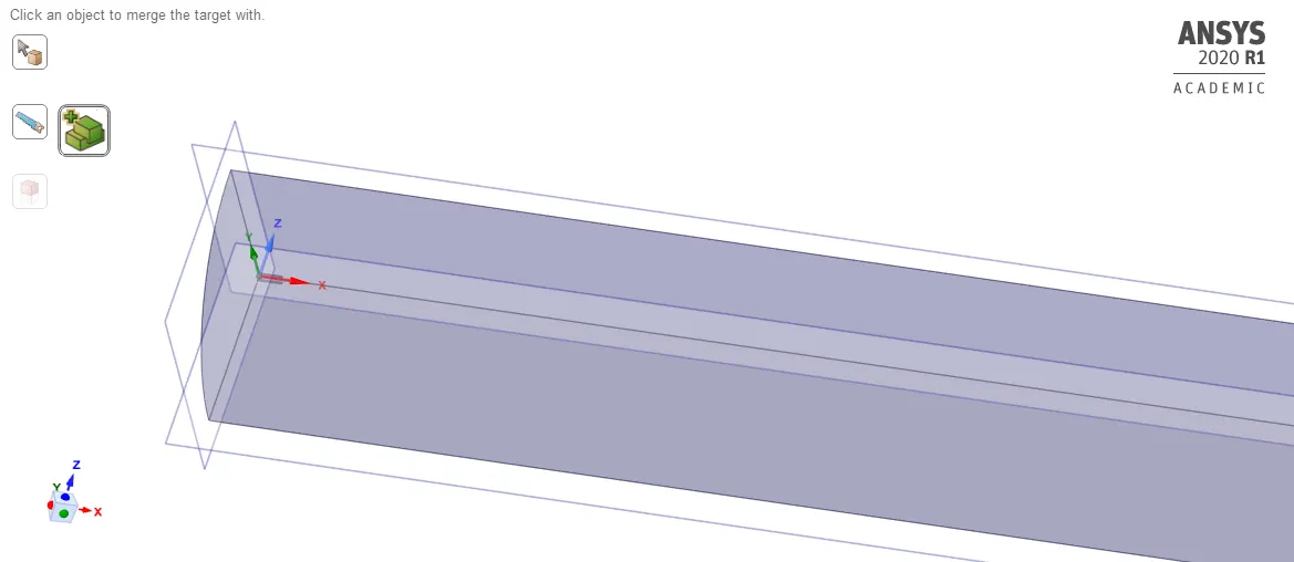
Copy this part:
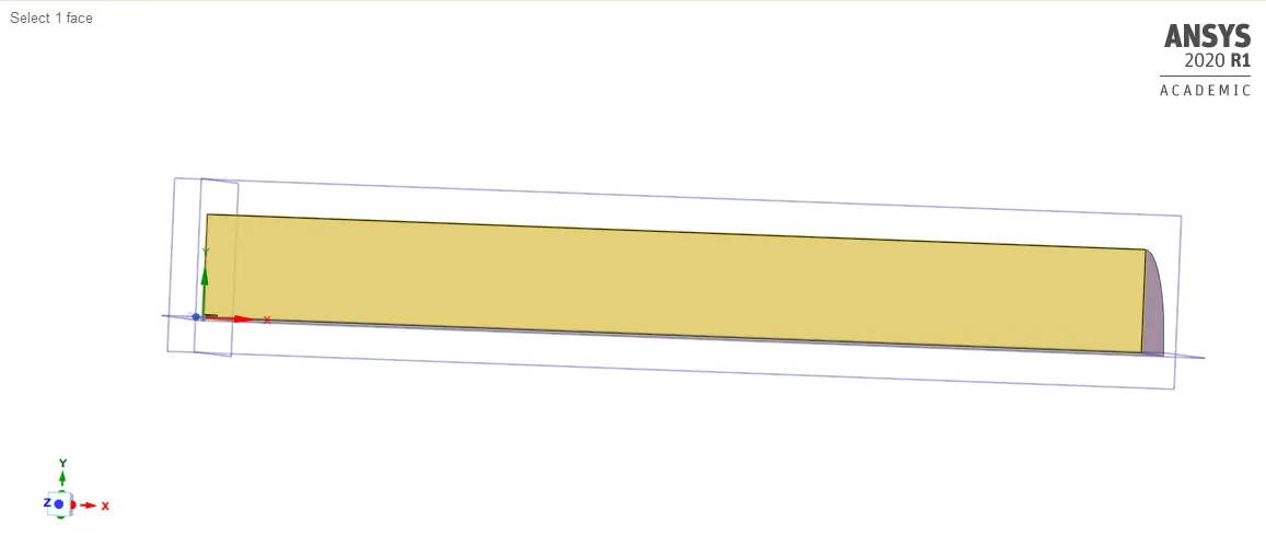
And paste it into the new design window:
Meshing:
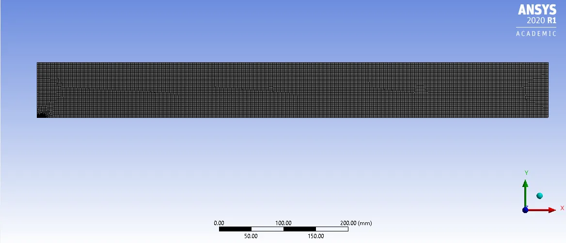
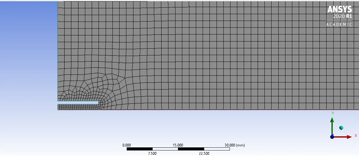
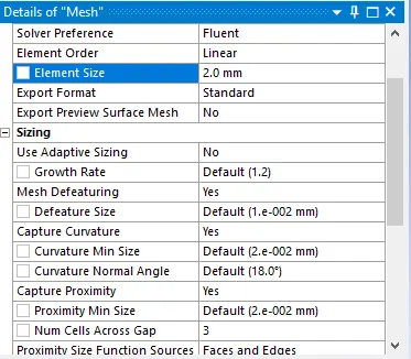
Details of Mesh:

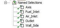
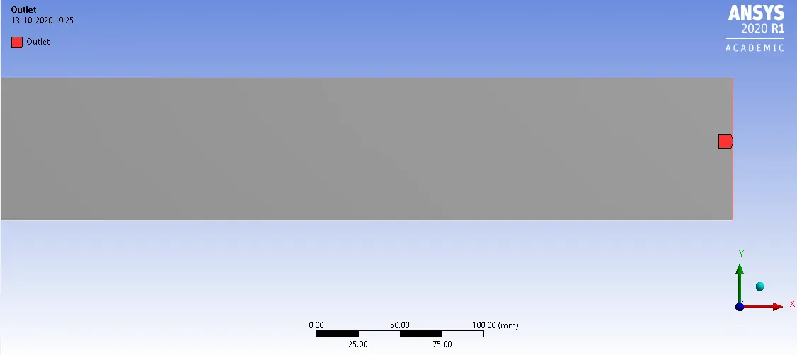
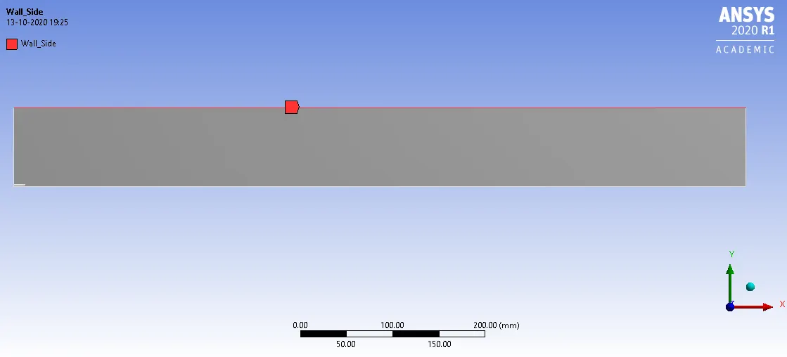
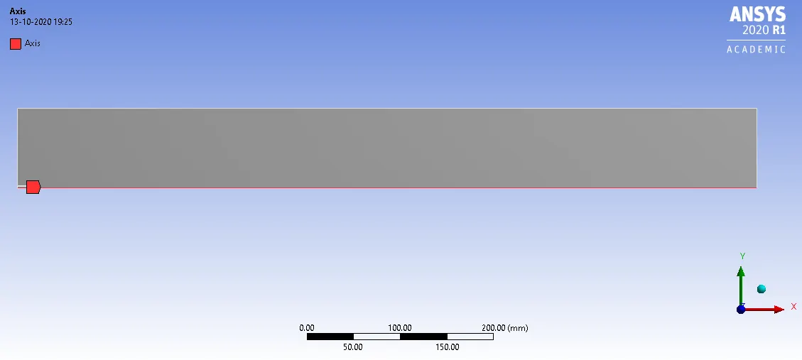
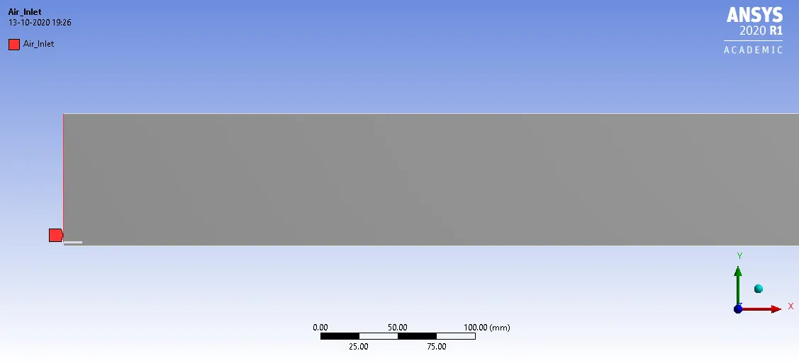
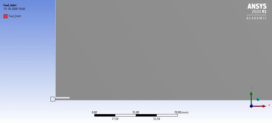
Named selections:
Fluent Setup:
Solver: steady-state, pressure-based, absolute, and axisymmetric.
Viscous model: K-epsilon, standard, standard wall treatment.
Boundary conditions:
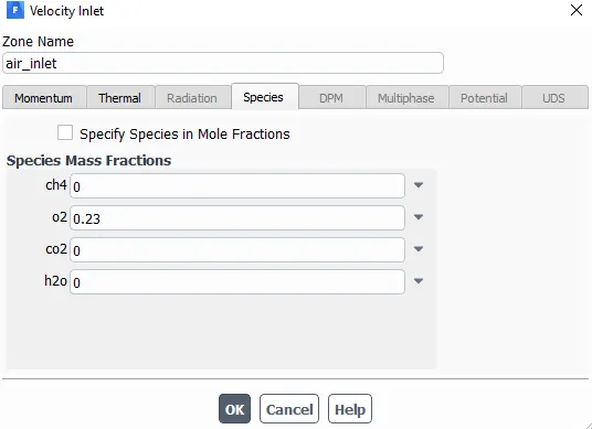
Air-inlet :Velocity: 0.5m/s.
Temperature: 300K.
species mass fraction: O2(0.23).
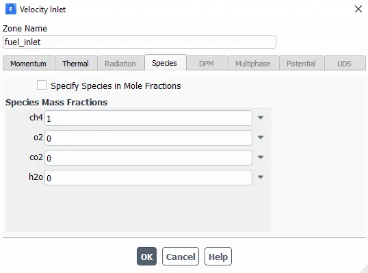
Fuel-inlet:Velocity: 80m/s.
Temperature: 300k.
species mass fraction: CH4(1.00).
Outlet: Pressure outlet(0Pa).
Species Model:
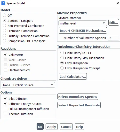
Since we are simulating the combustion we have to turn on the turbulence model to make the species and combustion-related models for work. Models that are selected in the species are as shown in the picture below. Most fuels are fast burning and the overall rate of reaction is controlled by turbulence mixing. In this model, the chemical reaction is governed by a large-eddy mixing time scale. Combustion initiates whenever there is turbulence present in the flow. It does not need an ignition source to initiate the combustion.
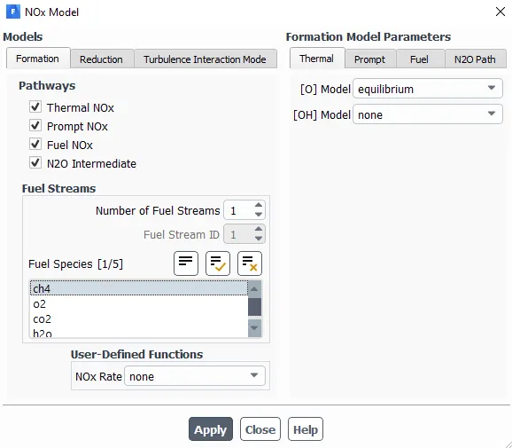
NOx model is activated to get the amount of NOx generated in the reaction.:
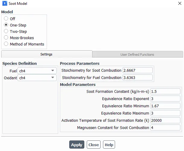
Hybrid Initialization and run the cases for 1500 iterations.
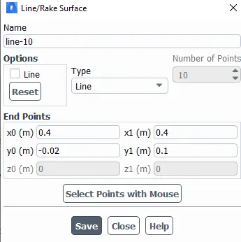
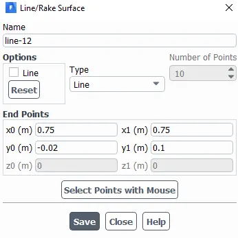
Create Line:
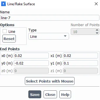
Create line plots:
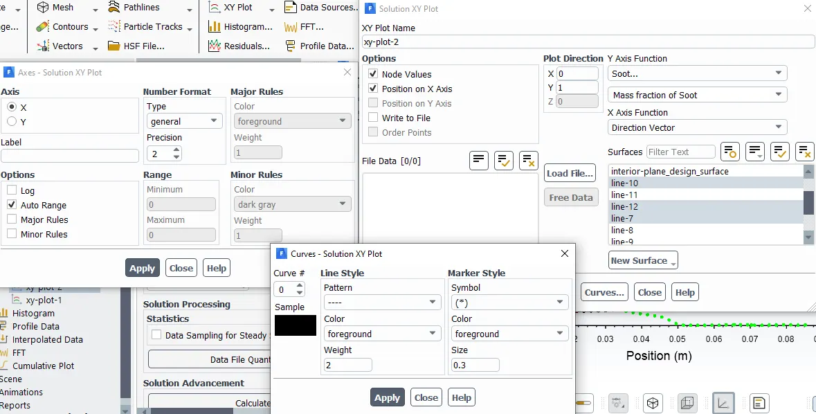
Results>XY Plot
Results:
Part I: Perform a combustion simulation on the combustor model and plot the variation of the mass fraction of the different species’ in the simulation using line probes at different locations of the combustor as shown in Fig. You need to plot for CO2, H2O, CH4, N2, O2, NOx emissions & Soot formation.
Create line plots at Report definitions- Area weighted average and select line.
Case-1:
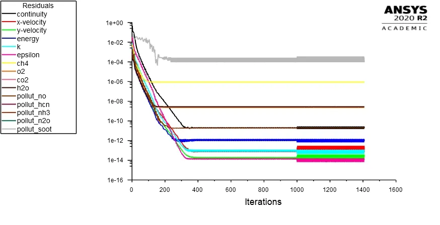
Residual Plots:
Temperature contour plots:
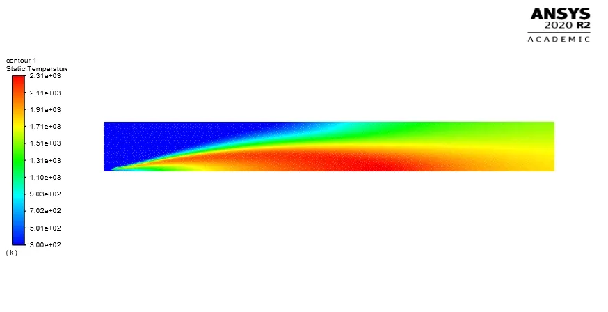
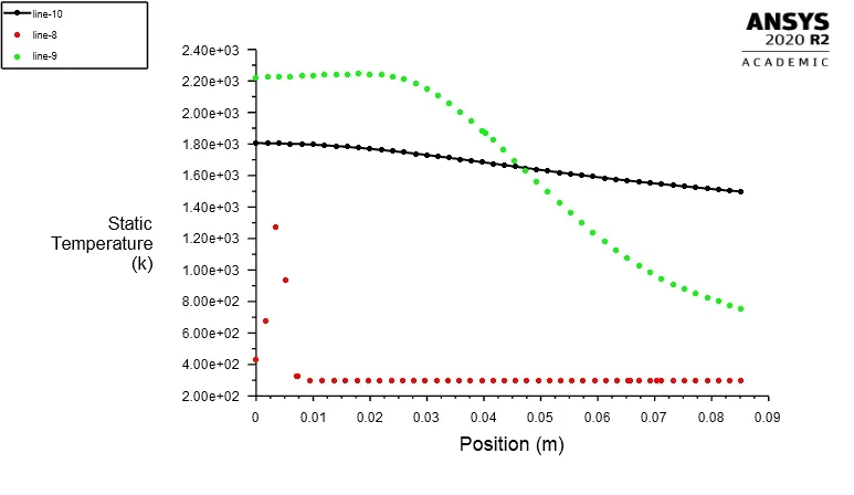
Mass fraction of CO2 and Line plots:
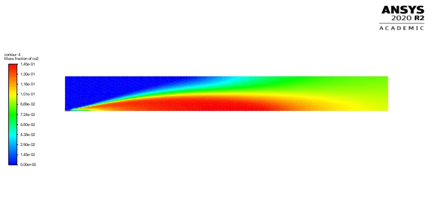
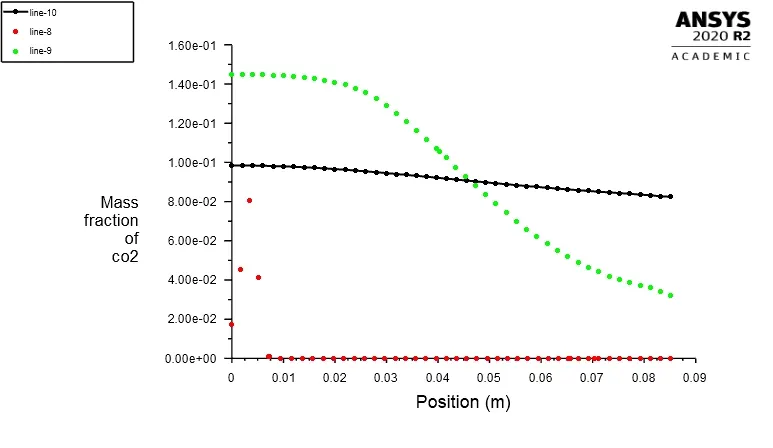
Mass fraction of H2O and Line plots:
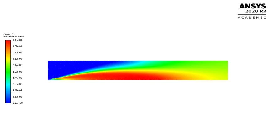
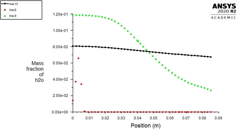
Mass fraction of CH4 and Line plots:
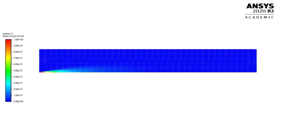
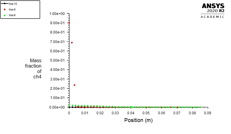
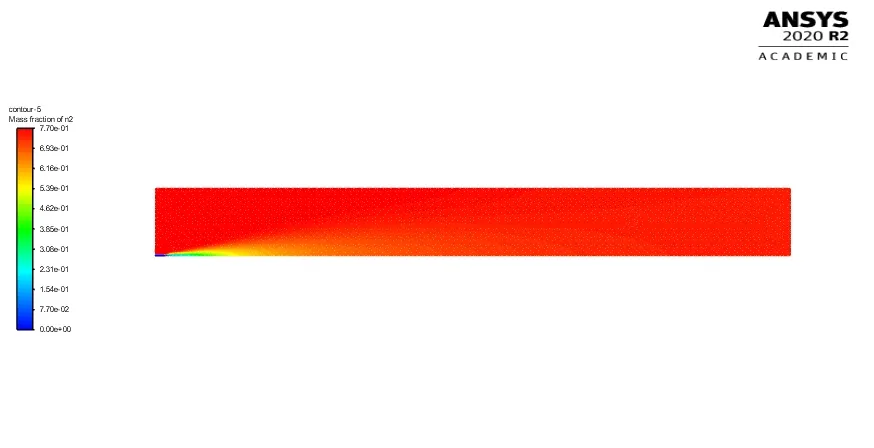
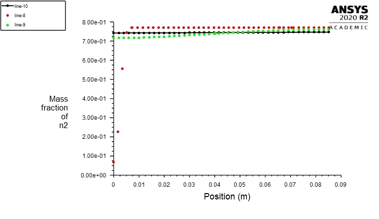
Mass fraction of N2 and Line plots:
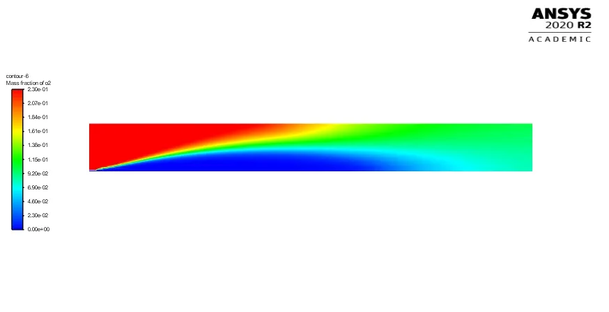
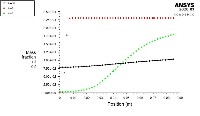
Mass fraction of O2 and Line plots:
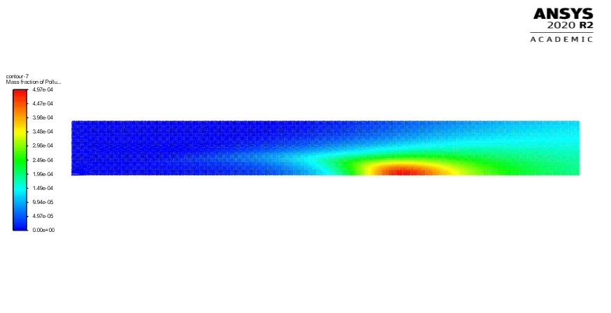
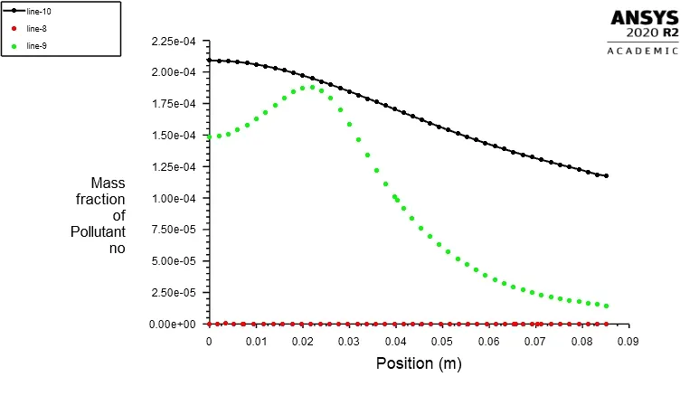
Mass fraction of NOx and Line plots:
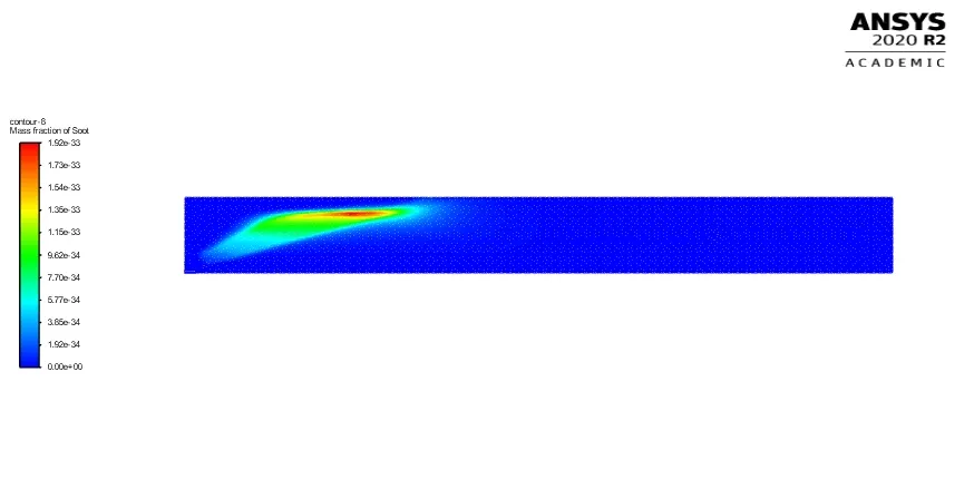
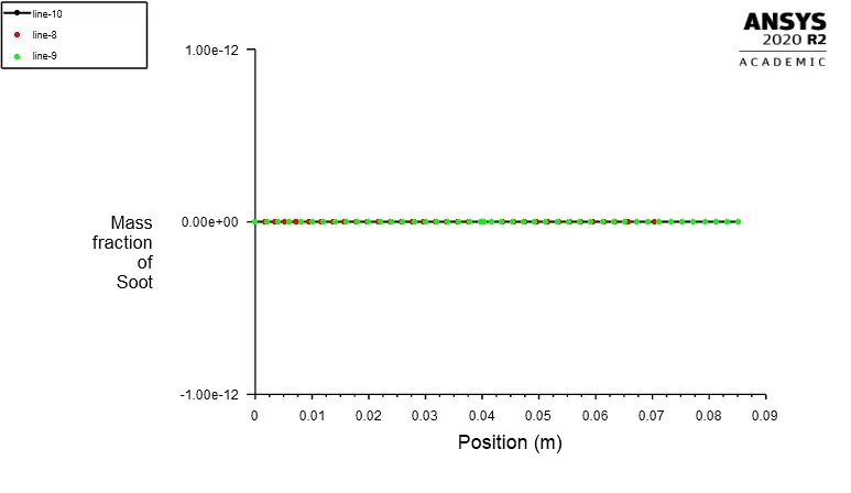
Mass fraction of Soot and Line plots:
Case-2:
(a):5%of water in the fuel
CH4=0.95 , H2O=0.05.
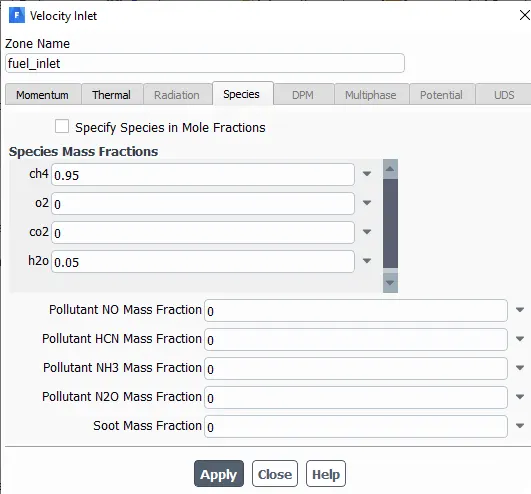
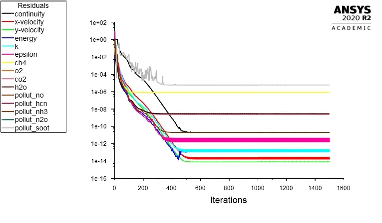
Residual Plots:
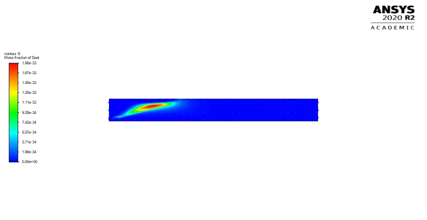
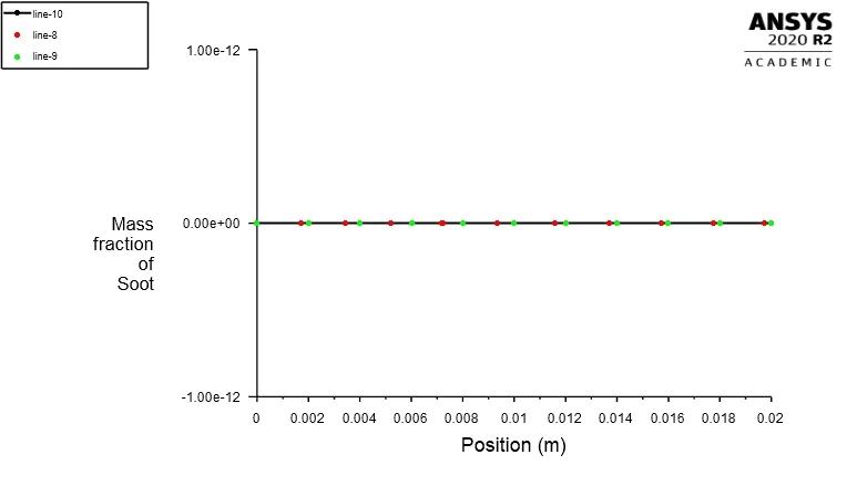
Mass fraction of Soot and Line plots:
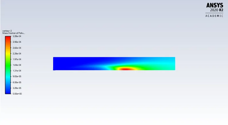
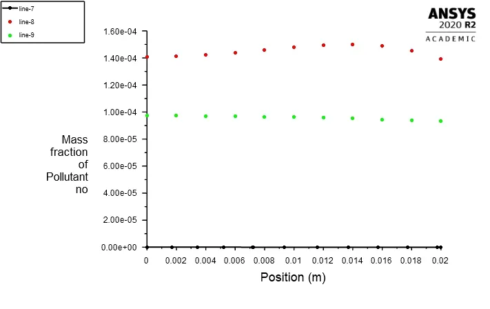
Mass fraction of NOx and Line plots:
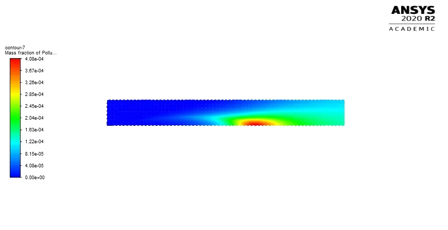

(b):10%of water in the fuel
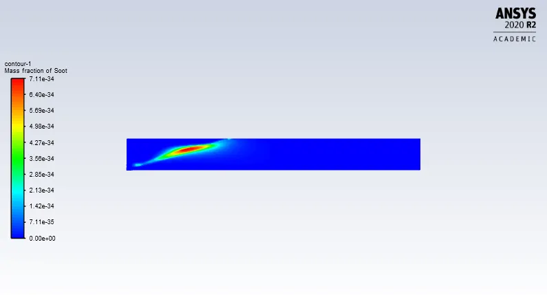
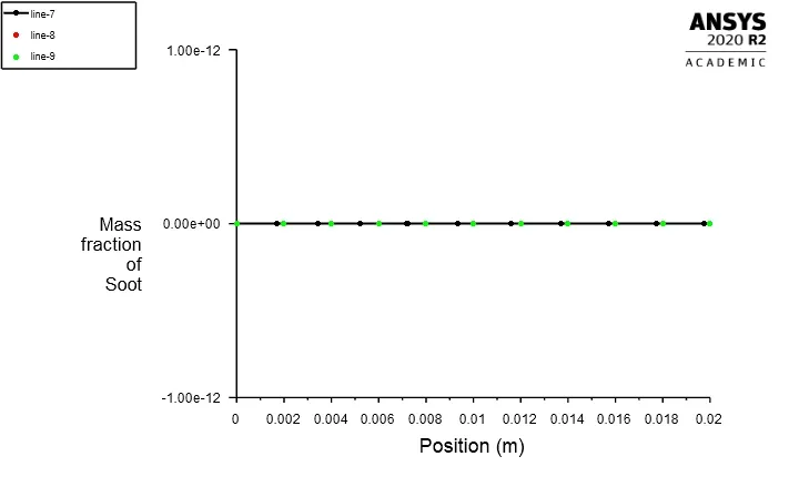
CH4=0.90 , H2O=0.10.
Residual Plots:
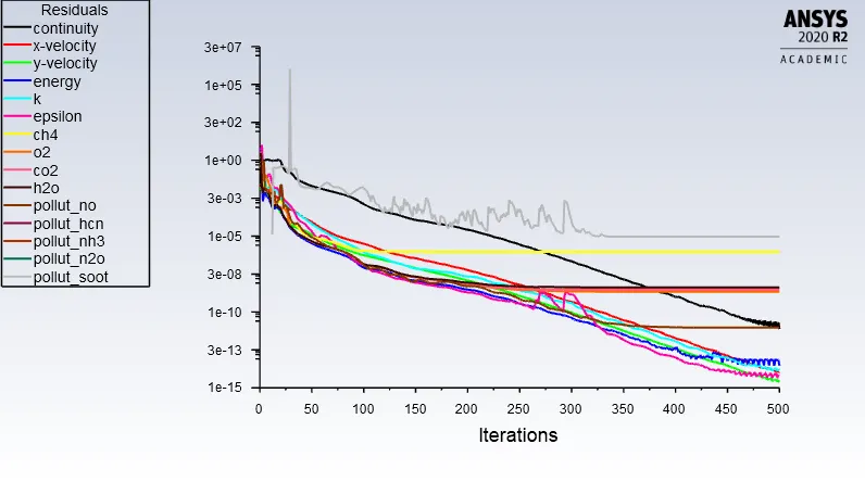
Mass fraction of Soot and Line plots:
Mass fraction of NOx and Line plots:
(c):15%of water in the fuel
CH4=0.85 , H2O=0.15.
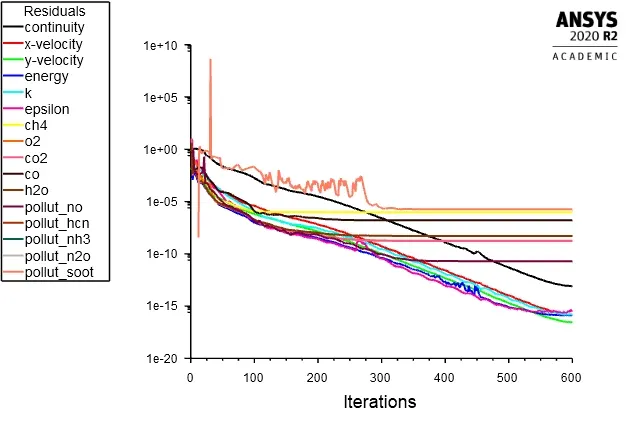
Residual Plots:
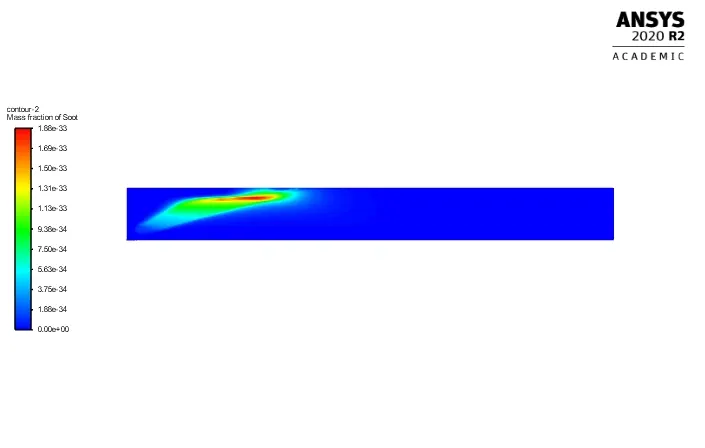
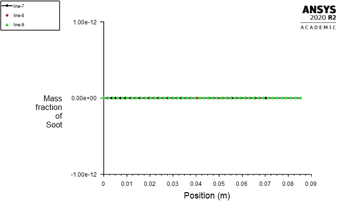
Mass fraction of Soot and Line plots:
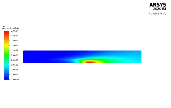
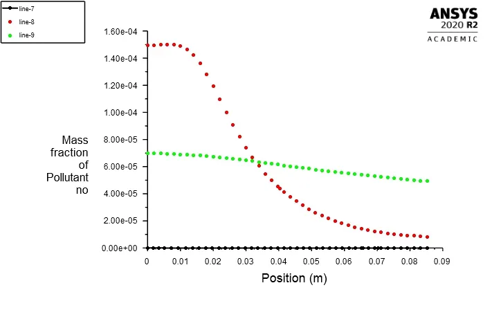
Mass fraction of NOx and Line plots:
(d):20%of water in the fuel
CH4=0.80 , H2O=0.20.
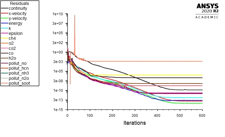
Residual Plots:
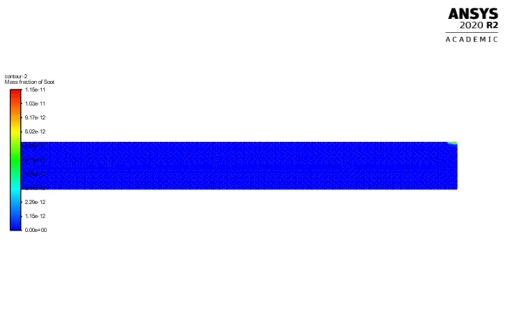
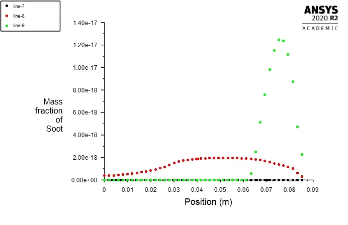
Mass fraction of Soot and Line plots:
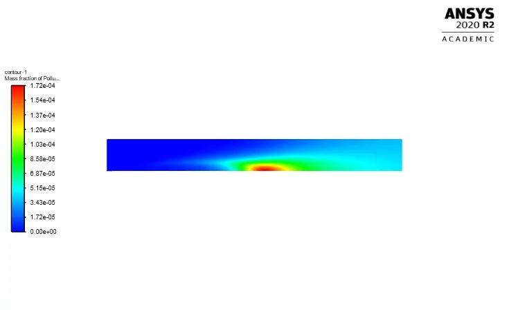
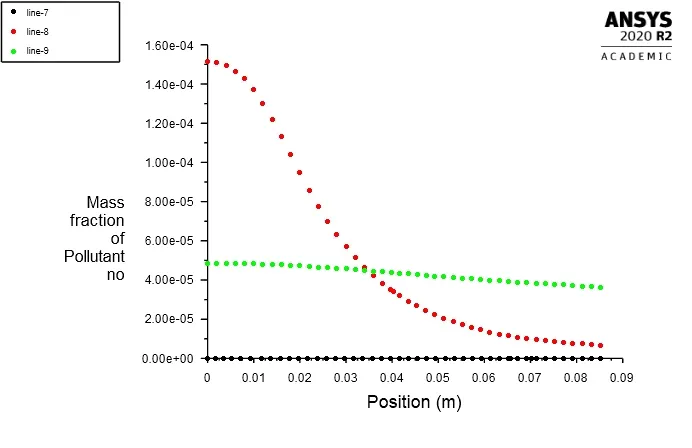
Mass fraction of NOx and Line plots:
(e):25%of water in the fuel
CH4=0.75 , H2O=0.25.
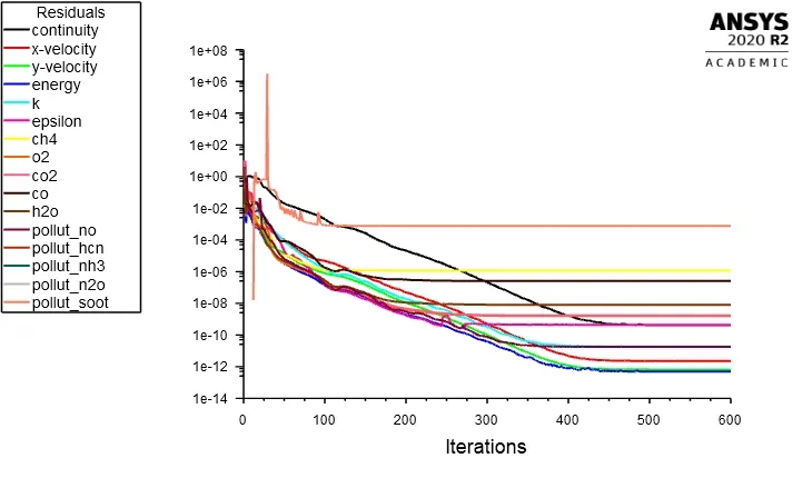
Residual Plots:
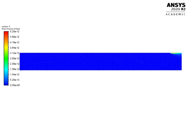
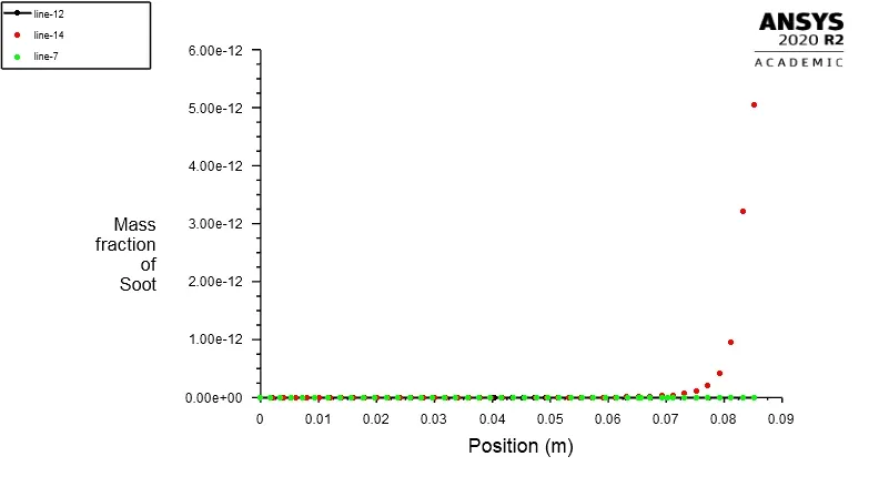
Mass fraction of Soot and Line plots:
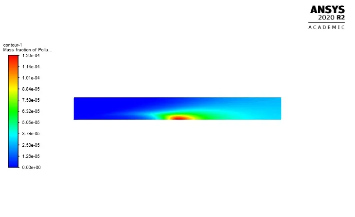
Mass fraction of NOx and Line plots:
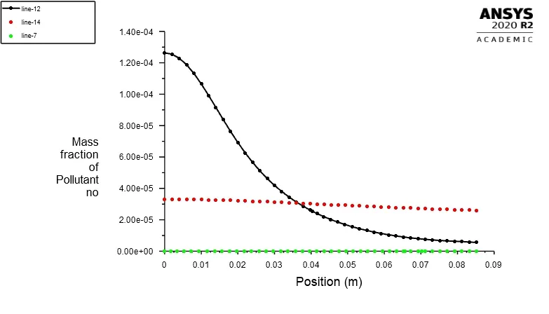
(f):30%of water in the fuel
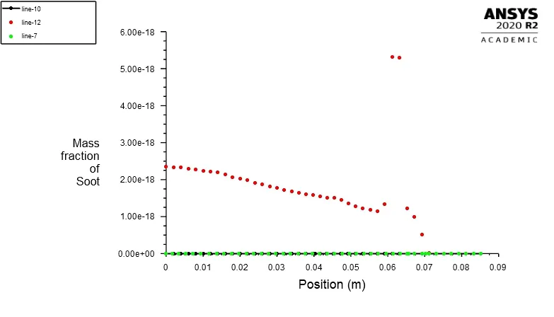
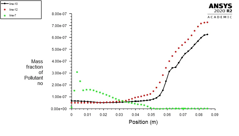
CH4=0.70 , H2O=0.30.
Residual Plots:
Mass fraction of Soot and Line plots:
Mass fraction of NOx and Line plots:
Conclusions:
- NOx species is present in a very low mass fraction which is quite negligible. NOx concentrations generated in combustion systems are generally low. As a result, NOx chemistry has a negligible influence on the predicted flow field, temperature, and major combustion product concentrations. It follows that the most efficient way to use the NOx model is as a postprocessor to the main combustion calculation.
- CO2, Temperature, and H2O have similar kinds of contour, which tells us that this species mass fraction depends on the effective combustion.
- If there is enough turbulence mixing of fuel and air, the eddy dissipation model will form a reaction and creates combustion depending on the amount of mixture present in that cell.
- As the water content in the fuel is increased, there is a drop in the level of nitrogen oxides. Also, soot levels got decreased.
- The temperature will increases as the water content is added to the fuel.
- As water is added, Unburnt hydrocarbons form at a much faster rate.
- Incomplete combustion could be a result of having water.
References:
1. https://www.sciencedirect.com/science/article/pii/S1876610217337724
2. https://link.springer.com/article/10.1007/s00773-015-0303-8