Challenge: Induction Motor-2
Question
- Discuss about the equivalent circuit network of induction motor MATLAB model.
- 3 phase, 50 Hz induction motor, represented by equivalent circuit constants X1 = X2 = 0.1 ohm and R1 = R2 = 0.2 ohm is operated at half of rated voltage and frequency. Calculate the ratio of starting torque at half voltage & frequency to rated values.
- Make a MATLAB script file which will plot speed torque characteristics for frequency control method.
- Explain in brief about operation of BLDC motor.
Answers
#1
Shown below is the simplified Equivalent Circuit of an Induction Motor.
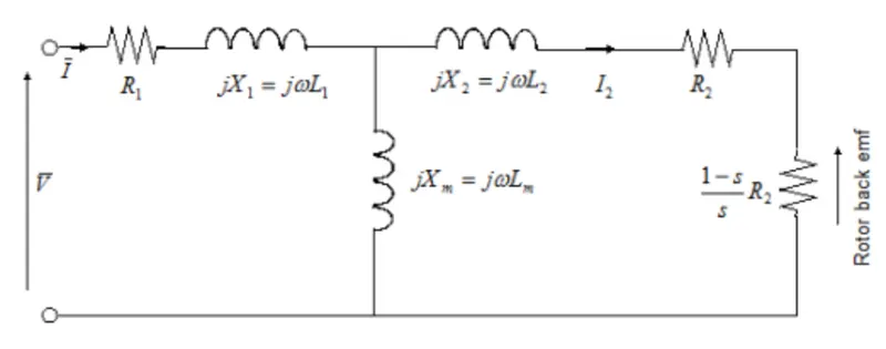
Here,
`R_1` is the stator resistance.
`R_2` is the rotor resistance with respect to the stator.
`X_1` is the stator leakage reactance.
`X_m` is the magnetising reactance required to cross the air gap.
`R_c` is the core losses.
`L_1` is the stator inductance.
`L_2` is the rotor inductance.
`L_m` is the magnetizing inductance.
`s` is the rotor slip, is given by `s = 1-(pomega_m)/omega`. This means that the slip is one when starting and zero when running synchronously with supply frequency.
`V` and `I` are the sinusoidal supply voltage and current phasors.
For an n-phase induction motor, the torque-speed characteristics is given by `T = (npR_2)/(somega)(V_(rms)^2/((R_1+R_2+(1-s)R_2/s)^2+(X_1+X_2)^2))`
Here, `V_(rms)` is the supply voltage, `n` is the number of phases and `p` is the number of poles.
This simulink block produces a positive torque acting from the mechanical C to R ports. The block can be parameterized in terms of the preceding equivalent circuit model parameters or in terms of the motor ratings.
Thermal Ports -
The block has 2 optional thermal ports - one per winding, hidden by default. To view the hidden ports, right-click on the block, from the context menu select Simscape > Block choices > Show thermal port. This action displays the thermal ports on the block icon and the shows the Temperature dependence and Thermal Port parameters
The ports are used to simulate the effects of copper resistance losses that convert electrical power to heat.
The block does not model the starting mechanism for a single-phase induction motor. When the block is parameterized by the motor ratings, the block derives the equivalent circuit model parameters by assuming that the effect of the magnetizing inductance is negligible, and the magnetizing inductance is not included in the simulation component.
#2
Given data,
Number of phases = 3
Rated Frequency, `f = 50 Hz`
Rated half Frequency, `f' = 25 Hz`
Stator inductance, `X_1 = 0.1` ohm
Rotor inductance, `X_2 = 0.1` ohm
Stator resistance, `R_1 = 0.1` ohm
Rotor resistance, `R_2 = 0.1` ohm
Torque, `T = (3/(omega_(ms)))((V^2.R_2/s)/((R_1+R_2/s)^2+(X_1+X_2)^2))`
`omega_(ms) =` synchronous speed
`R_1 =` stator resistance
`R_2 =` rotor resistance
`X_1 =` stator inductance
`X_2 =` rotor inductance
`s =` slip
Rated synchronous speed,
`omega_ms = (120*f)/p`
`=(120*50)/p`
`= 6000/p`
Half of rated synchronous speed,
`omega'_ms = (120*f')/p`
`= (120*25)/p`
`= 3000/p`
Rated torque,
`T = (3/(omega_(ms)))((V^2.R_2)/((R_1+R_2)^2+(X_1+X_2)^2))`
`T = (3/(omega_(ms)))((V^2 *0.2)/((0.2+0.2)^2+(0.1+0.1)^2))`
`T = (3*V^2)/(omega_(ms))`
Rated half torque,
`T' = 1/2(3/(omega_(ms)))(((V/2)^2.R_2)/((R_1+R_2)^2+(X_1+X_2)^2))`
`T = 1/2(3/(omega_(ms)))(((V^2 *0.2)/((0.2+0.2)^2+(0.1+0.1)^2))`
`T = (1.5*V^2)/(omega_(ms))`
Ratio of Half rated torque and Rated torque,
`(T')/T = ((1.5*V^2)/(omega_(ms)))/((3*V^2)/(omega_(ms)))`
`(T')/T = 1/2`
`implies` The ratio of starting torque to half torque is `1/2`.
#3
MatLAB code for the program is shown below,
close all
clear all
clc

%inputs
p = 4;                  %number of pole pairs
s = linspace(0,1,100);  %slip
R1 = 0.6;               %Stator resistance
R2 = 0.3;               %Rotor resistance
X1 = 1.2;               %Stator inductance
X2 = 0.7;               %Rotor inductance
V = 400/sqrt(3);        %Voltage per phase
f = linspace(0.5,2,5);  %Frequency

for i = 1:5             %FOR loop for account different frequencies
omega = 120*f(i)/p;     %Synchronous speed
for j= 1:100            %FOR to account different slip values
    wm(j) = (1-s(j))*omega; %rotor speed
    T(j) = ((3/omega)*(V^2*R2/s(j))/((R1+(R2/s(j)))^2+(X1+X2)^2)); %Torque equation
    T(1) = 0;           %T(1) does not automatically become 0 as s(0) = 0 in the torque equation denominator

end

%Plot
plot(wm,T,'linewidth',1.5)
hold on
title('Speed-Torque Characteristics  for Frequency Control')
xlabel('Speed - rad/s')
ylabel('Torque - Nm')
grid on

end

legend('Frequency 1','Frequency 2','Frequency 3','Frequency 4','Frequency 5','location','northeast')
Here a nested FOR loop is used to compute the Speed-Torque characteristics for frequency control. The outer loop controls the frequency and the inner loop computes the torque for different slip conditions and plots the graph.
Result
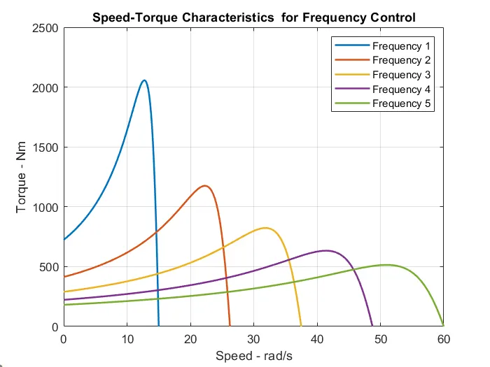
It can be seen from the above graph that as frequency increases the peak torque decreases also the speed range of the motor increases with the increase in frequency. Here all the parameter were kept same and frequency was varied.
#4
BLDC Motor
A brushless DC motor (BLDC) is a permanent magnet synchronous electric motor which is driven by direct current (DC) electricity and it accomplishes electronically controlled commutation system - it is the process of producing rotational torque in the motor by changing phase currents through it at appropirate times, instead of a mechanical commutation system.
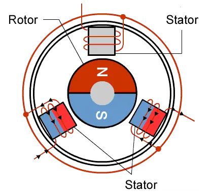
Unlike conventional brushed type DC motor, wherein the brushes make the mechanical contact with commutator on the rotor so as to form an electric path between a DC electric source and rotor armature windings, BLDC motor employs electrical commutation with permanent magnet rotor and a stator with a sequence of coils. Here, the permanent magnet/field poles rotates while the current carrying conductors are fixed.
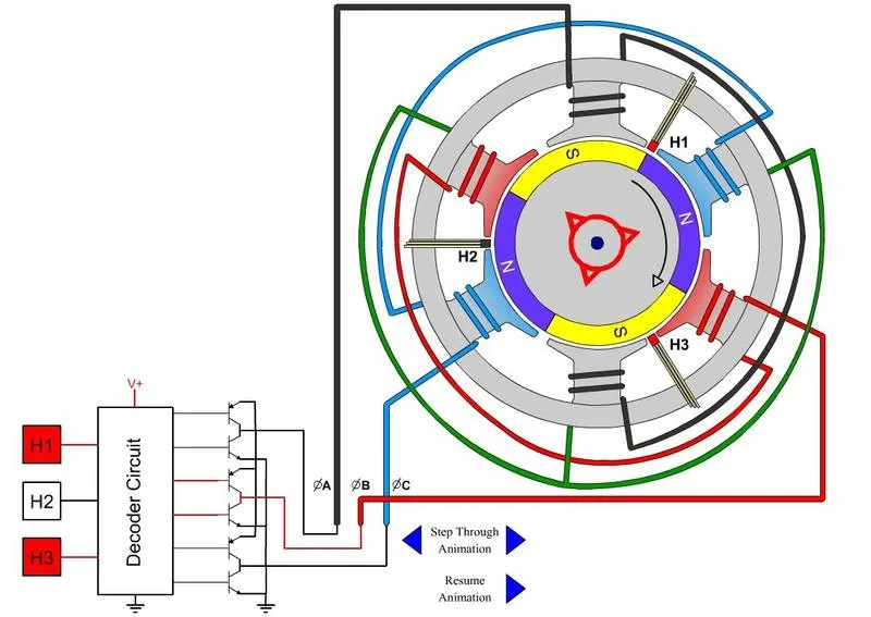
The armature coils are switched electronically by transistors at the correct rotor position in such a way that the armature field is in space quadrature with the rotor field poles. Hence the forces acting on the rotor forces it to rotate. Hall sensors or rotary encoders are most commonly used to sense the position of the rotor and the feedback is used to determine when to switch the armature current.
These arrangements makes the BLDC motor more reliable and less noisey during operation, due to the absense of the brushes they are capable of running at high speeds. Typically a brushed DC motor has an efficiency in the range of 75 to 80% whereas BLDC motors are 85 to 90% efficient, they also produce large amounts of torque over a vast speed range.
Advantages
- Smaller motor geometry and light weight than brushed DC and AC induction motors.
- It has not mechanical commutator and associated problems.
- High speed operation in loaded and unloaded conditions.
- Quite operation due to absence of brushes.
- Less electromagnetic interference.
- Reliable and long life.
- High efficiency.
Disadvantages
- Requires electronic controllers which are expensive.
- Requires complex drive circuitry.
- Additional sensors are required.
- Motors are costly.